Demolition and Replacement of the Centrepoint Tower by John Millard:

Figure 1: Map of Central London
The intersection of Oxford Street, Tottenham Court Road, New Oxford Street and Charing Cross Road is where The CentrePoint Tower is located in St. Giles Circus. The Circus is a large space that requires egress by pedestrians from London Underground Station, Tottenham Ct. Road - one of the most heavily travelled tube stations in London.

Figure 2: Location plan showing demolished Centrepoint Tower in an empty St. Giles Circus.
This study map formed the sequence of public spaces that the West End of London offers a pedestrian traveling from Trafalgar Square to Euston Center via Leicester Square, Soho Square, Seven Dials, Cambridge Circus, St. Giles Circus, Bedford Square, Fitzroy Square, and Bloomsbury Square. The planning of st. Giles Circus was informed by this experience of travelling across the West End.

Figure 3: Strategic Diagram shows footprint of proposed tower and associated proposed pavilions that serve as egress/ access to London Underground Tube Station Tottenham Court Road.
This diagram shows how the tower was never meant to exist as an anomalous building on its own. The four, heroic pavilion versions of the tower create a context that make a family of buildings that are related to the tower, oozing with pedestrians. The open space invites St. Giles Church by Hawksmoor to be present, with it's passageways from Covent Garden.

Figure 4: Schematic Site Plan showing treatment to the south west facade of the tower.
As aeronautical forces began to inform the design of the tower, gargoyle-like aerofoils that move across the lower south western facade to which the prevailing south west wind traditionally had made pedestrian occupation of the outdoor plaza quite windy from wind shear as a result of the geometry of the original Centrepoint Tower.

Figure 5: Schematic Ground Floor Plan of the New Centre Point Tower.
This plan shows the shear walls that form steel sheet pile shells. These shells of two directional core ten sheet pile (a sandwich of vertical and horizontal sheet pile with an in-situ concrete core) rise out of the foundations as large tubes (with local openings) and read open as the tower increases in height.

Figure 6: Reflected Ceiling Plan of New CentrePoint Tower ground level entry.
Outdoors comes in; The transparent metal canopy that spans over the entrance lobbies of the ground floor seamlessly exfiltrates out through the weather-tight envelope of the lobby to incorporate the metal braces that constrain the movement of the aeronautical gargoyles in the z axis.

Figure 7: Building Section showing transfer floors, elevator shafts, shear walls and external turbulence system.
This drawing, which was derived from the actual band saw section through the 1:500 balsa model that was wind tunnel tested, is an accurate representation of the contours that successfully induce updraft when air encounters the southwestern facade at thirty kilometres per hour or more. The transfer floors occur every 30 meters and allow for disparate volumes of tenant space to occur inside of these transfer floors.

Figure 8: SouthWest Elevation showing structure and omitting skin.
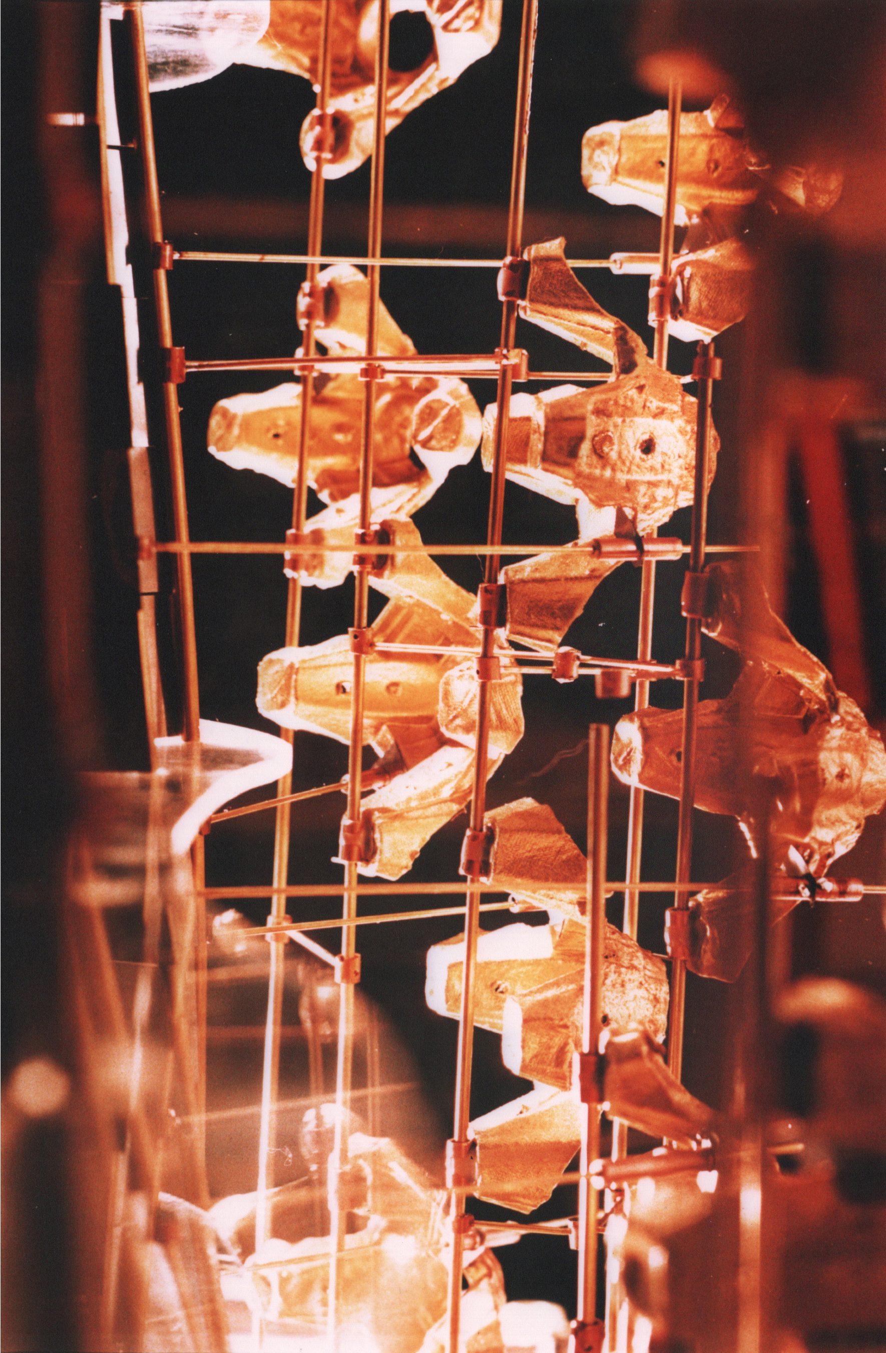
This drawing is actually based upon the 1:200 model that was tested in the wind tunnel at Kingston Polytechnic. What is not shown is the glazing skin that is supported by wind bracing and forms the weather envelope of the building. The external turbulence system shown in the foreground of the elevation is deigned to address the prevailing winds at the site by inducing updraft by channelling the laminar flowing air into an upward movement along the contours of the southwest facade.

Figure 9: Aerial Photo of CentrePoint from SouthWest.
Here in this image, the existing site can be seen with construction activity occurring in 2012 at St. Giles Circus. The context of the photo shows the British Museum in the background, Soho Square in the foreground, Bedford Square near the British Museum and Cambridge Circus to the lower right corner of the photo.

Figure 10: Photomontage showing new Centrepoint Tower in place of Existing Centrepoint Tower.
The New Centrepoint Tower, montaged into the photo above is slightly taller than the Existing Centrepoint Tower at 210 meters. The orientation is more southwesterly than the Existing Centrepoint Tower. The entire structure revolves southward as the height of the structure increases. This is similar to a plant straining to receive more sunlight, it twists toward the sun ignored to achieve more photosynthesis for food and growth.

Figure 11: External Turbulence System controls views out of the New Centrepoint Tower from the lower levels.
The Gargoyles, which are fabricated from special fabric and metal frames borrowed from certain Susumu Shingu Projects are designed to increase micro turbulence at the lower levels creating a shape that channels the laminar flowing air into a chute that is upward in direction. The facade of the southwest is shaped to induce this updraft. Views out of this wind screen are obstructed by these Susumu Shingu type structures and they also move in a controlled fashion, slowly rotating in the z axis as they self direct themselves into the changing wind direction.

Figure 12: Model Photo- View from Tottenham Court Road
Looking up from the entrance to the Virgin Atlantic Superstore, the New Centrepoint Tower has a curious, oblique view when seen from the north west. The smooth scoop-like shape that the south west facade reveals from this angle is curious and in contrast to the staccato presence of The Gargoyles in the External Turbulence System.

Figure 13: Model showing the plane of the facade using monofilament wire.
This model was clad using clear plastic by weaving the sheet of plastic in and out of these monofilament wires in order to simulate a smooth surface that accurately represented the exterior envelope of the building for use in the wind tunnel at Kingston Polytechnic. The last has been removed in this photo, but the shape of the exterior can clearly be seen forming the shape of the building.

Figure 14: Model scaled at 1:200 of the structure using a white background.

Figure 15: "Before and After" using the model photograph as the basis for the Southwest Elevation

Figure 16: Color Photos of the 1:200 model used in the Kingston Polytechnic Wind Tunnel.

