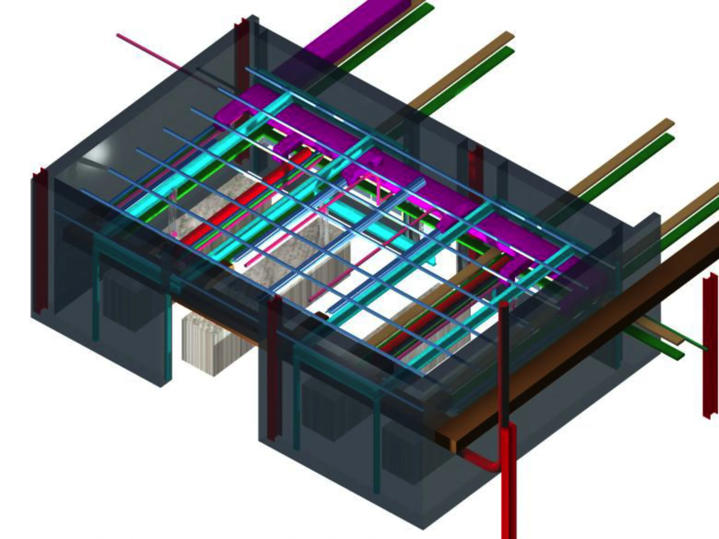
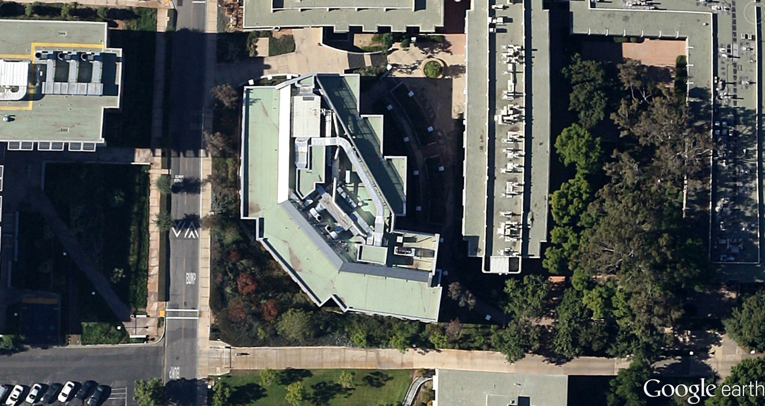
Neurological Research Institution associated with The Royal Institute of Neurology- Schematics
Architecture Firm: Devereux Partnership
Client: Royal Institute of Neurology
Site: Queen Square, London
Date of Project: 1993- 1995
Project Summary: This new building, sponsored by The Welcome Trust and The Royal Institute of Neurology- next-door-neighbor to the site of A Functional Brain Imaging Laboratory resulted in the demolition of St. John's House, an early twentieth century convent. In its place, a medical imaging lab for the study of episodic memory and other neurological conditions that utilized PET & MRI Scanning with an on-site Cyclotron (particle accelerator) and a Nuclear Medicine Lab (Blood Gas Analysis). The building probably should have been built in a green field site, away from the city- but for the critical relationship with the Royal Institute of Neurology (next door) the project was crammed into a footprint that was difficult to coordinate ground work, utilities and foundation structure and radiation protection.
John Millard's Role- I stayed with the project throughout all phases of design to construction when I joined the construction team and followed the project to construction completion as part of my RIBA Part III Case Study. There was one other (technical) architect working with me from design development to construction documents. We both reported to a principal in charge of the project.
Specific Role by John Millard: 1) Originate all CAD drawings, 2) Lead contact with Construction Management Team, 3) Coordinate Engineering Disciplines, 4) Communicate Equipment requirements from manufacturers to engineering team. 5) Produce all Schematic Phase Drawings for approval by Owner, 6) Produce all Design Development Phase Drawings for approval by Owner, 7) Produce all Construction Documentation Phase Drawings for approval by Owner/ CM.
Contents:
1) Chapter One
a) Client introduction
b) Devereux Partnership Architects
c) The Site
d) The Brief
e) The Project Manager
f) The Structural Engineers
g) The Services Engineers
2) Chapter Two- Programming for A Functional Brain Imaging Laboratory:
a) The MRI suite
b) The Pet Camera
c) The Cyclotron
d) Ancilliary Functions
e) other functions
f) upper levels
3) Chapter Three- Planning A Functional Brain Imaging Laboratory:
a) The Architecfs Description of the Project
b) When council architects "make suggestions"
c) Preservation orders! third parties! project manager/ coordinator
d) Salvaging a scheme from the committee design
e) How retaining the Facade complicated the project
4) Chapter Four- Adjacent Properties:
a) The Project Manager as Arbitrator between Client Parties"
b) The Project Manager as Arbitrator between Client & Third Parties
e) Party-Walls & Payouts to Adjoining Owners
g) After all, whafs left for the architect to do?
5) Chapter Five- Why was an architect requitrecl to design F.B.I.L?
a) Labor Intensive nature of Healthcare Projects
b) The Requirement for Design & Planning
c) Architect as Quality Safeguard for Client
d) One comparison of JCT80 with Project Manager's Contract
e) Variation under Project Managed Contract v JCT 198
f) Variations in practice, on site
g) Health & Safety on the Project Managed Site
6) Chapter Six- Cost Over-runs Underground
a) The LEB Substation: exacerbating high cost civil works
b) when poor design coordination results in underground cost over-runs...
7) Chapter Seven- Scheme Design Stage
a) Evolution of radiation containment
b) The effect of Mass Concrete upon Substructural Design & Cost
c) Communications with Siemens
d) The effect of Scheme Design upon the Project Manager's perceptions
8) Chapter Eight- Detail Design" Tender of the MRI Suite
a) Radio frequency, Magnetic Waves, and Means of Escape
b) Ferrous implants in Human Beings and Health & Safety
c) Means of Escape from the MRI Suite
d) Tender Interviews for a magnetic shield
e) Coordination of Mechanical & Electrical Engineering
9) Conclusion
Chapter 1- Client profile: The Institute of Neurology
A neuro-scientist named Dr. Richard Frackowiak and his colleagues from the Medical Research Council in Hammersmith developed new techniques for examining processes within the brain using modern imaging techniques. Dr. Frackowiak soon became frequently published in Nature Magazine and is a much sought after member of the medical scientific community.
The Wellcome Trust offered to incorporate Dr. Frackowiak into a leading role within a new arm of the Institute of Neurology called A Functional Imaging Laboratory. This would provide him with resources which would enable him to develop his research into cures for many neurological disorders such as Alzheimer's Disease.
The Devereux Partnership The Devereux Partnership began designing healthcare buildings in the late 1930s and have established themselves within mainstream healthcare architecture after their recent completion of the National Hospital Centre for Neurology & Neurosurgery in 1993. The success of this most recent project has meant that they have become short Iisted for manyhealthcare projects of late, and the Functional Imaging laboratory is one which is now under construction.
The Site: 12 Queen's Square An unlisted early 20th Century convent adjoined and was owned by the Institute of Neurology. This building was occupied by nurses of the National Hospital and had been planned to be decanted and demolished in preparation for the F.1. L. Project. Ifs existence within the surrounding Preservation Area became a source of conflict. A local conservation group attempted to have the building and a large plane Tree in the rear of the site listed by the D.o.E. Neither were listed buildings but pressure from the Bloomsbury Conservation Society provoked the planners to ·suggest- that the portland stone which formed the Piano Nobile should be retained if possible- intact and if not possible, then each stone surveyed, catalogued, and rebuilt as part of the main fa9ade which should resemble the existing building as much as possible. The following drawing describes the existing main elevation onto Queen's Square:
The Client Brief- Functional Brain Imaging laboratory According to minutes of the first design team meeting held on 24th February, 1993, the project manager stated that details for the brief are to be collected by talking to the relevant people at the Medical Research Council Unit at Hamr'Dersmith. This was indication enough that the client, who wanted to build a brain scanning laboratory had no brief to issue to the design team. Moreover, the Project Manager, who was the clienfs agent, gave this responsibility to the design team. This building, which should contain over £25M of electronic scanning equipment including a particle accelerator which constituted a class 1 radiation hazard was then entirely in the hands of RIBA qualified architects and appOinted consultants, none of whom were willing to accept responsibility for the performance of primary elements of the scheme such as the radiation shield. Never the less, they were willing to take the job on, with some assurance from the equipment manufacturer, Siemens PLC, that suggestions as to how to go about containing Gamma and Neutron Radiation would be forthcoming from Siemens. This meant that Siemens would perform calculations based on the known output of radiation from their two other cyclotrons which existed In the world and design a concrete maze to contain radiation based on these calculations. In addition to this, Siemens provided volumes of performance specifications which defined the operating tolerances of their equipment and the environmental requirements of the scanners themselves, of which I was personally responsible for having a working knowledge in order to design the general arrangements of the building. With the benefit of hindsight, the project manager should have allowed the Services Engineers more time to absorb the above requirements and then to accept strategic recommendations from the services engineers as to the way in which the services strategy could Inform the design of the building before proceeding with formal architectural preoccupations such as courtyards and copper roofs. Unfortunately, this did not happen. Instead, the services engineers found themselves restricted within a preconceived design which they then had to try to achieve compliance with what eventually became known as "the brier. To this day, a successful scheme has not been produced by the services engineers yet construction has begun. Services subcontractors are now expected to resolve the problems on site.
Mace Ud.- Project Managers
Problems which occurred before construction began started with the bankruptcy of the original project manager, Ake Larson, whose commitments associated with "The Ark" project in Hammersmith resulted in the demise of the U.K. subsidiary of that Swedish Firm. The person in charge of the project from Ake Larson's end carried the project to MACE Ltd, a well known group (ex-Bovls Construction Managers) of project managers in the City. There he became the F.I.L. Project Manager and has been the main coordinator of the project since discussion of a building to house the Functional Imaging Laboratory began. Were this responsibility left to an architect, the results might have been different. The suggested reasons for this will follow in the body of this paper. The Project Manager was responsible for so many aspects of the project that it is questionable whether the Devereux Partnership's role can be considered that of the traditional architects role. For example, Devereux was engaged by Mace under a bespoke contract (as were the other consultants and contractors) which left only Mace employed directly by the client. The Client consisted of two main parties, The Welcome Trust (who paid for the construction) and The Institute of Neurology (who owned the site and employed the expertise). The role of coordinating the client soon became a clear objective of the project manager when a dispute between the two part ownership of the site threatened the construction phase of the project just before demolition of the existing building began. The Project Manager helped to resolve this and many other third party disputes which erupted over the course of the project due to his stable character and determination to keep everyone involved contented yet on program and on budget. Coordination of the various disciplines involved in the project was never successfully achieved however, (whether perceived as the architecfs responsibility or the project manager's responsibility) and the consequences of this will not be fully known until the building's completion. Consultants on the project would unanimously agree that the project manager was best placed to perform a coordinating role. The Consultants were all employed by the Project Manager, therefore they could be considered to be in the best position to allocate blame when coordinating issues went awry. All Design Team meeting minutes were recorded by Mace and all actions called for were finalized by Mace. The minutes, a sampling of which are included In the appendix of this paper, are remarkably terse and devoid of comments or descriptions of the tensions and apprehensions which often prevailed on the design team. The Architects followed the instructions of the Project Manager even when a disagreement arose over the waterproofing (tanking) strategy arose. The architects were named as being responsible for keeping 25m of electronic equipment In the basement dry, and yet the project manager was able to silently veto the use of a certain service cavity drain waterproof membrane system. This system was favoured by the Architects and successfully implemented on previouS Devereux Buildings with Magnets in the basement including the National Hospital just across the square. However it was rejected on cost grounds, in favour of a less expensive "tried and tested" membrane. Other examples of over-turned decisions by the Architects which would ordinarily go unquestioned (or at best undefeated) by other Project Team Members will be touched on in this case study as will examples of the effectiveness and ineffectiveness of the role of the project management-led project in general. Ultimately, the responsibility which the Project Manager has taken upon himself Is to see that the building is constructed on time and is built on budget, in fact, this is the primary reason for his involvement in the project ... Nevertheless, the experience which the Mace team brought with them was considerable in both the CMI Engineering, Quantity Surveying, and Construction Management related disciplines. The Construction Manager on site was previouSly the main Bovis Site Construction Manager on both the Lloyds Building by Richard Rogers Architects and The International Passenger Terminal at Waterloo Station by Nicholas Grimshaw Architects.
WS, Kenchlngton Ford - Structural Engineers
Kenchington Ford pic is an integrated engineering consultancy formed by the recent merger of Kenchington Little pic and the Brian Ford Partnership. The company provides a combination of over seventy years of traditional consultancy experience, restructured to fulfill the requirements of the future. The company has over 350 staff operating from offices In London, Barnett, Bradford, Cambridge, Chester, Dundee, Edinburgh, Edgbaston, Glasgow, Leeds, Nottingham, Plymouth, Putney and Winchester. Divisions have been created within the company to provide specialist services in support of the offices as well as undertaking commissions In their own right. Each division is based at a Kenchington Ford office and operates throughout the country.Projects range from reports, Inspections and feasibility studies to full design, supervision and project management commissions for work in the UK and abroad. Their clients include government agencies, local authorities, financial institutions, developers,commercial and industrial companies, fellow professionals and contractors. The Engineering Division includes Structural & Mechanical engineering, CMIEngineering, Transport & Highways, Site services, Environmental, Terotechnotogy, Technical Directorate, and the Quality Assurance Directorate. Kenchington Ford assemble the following principal personnel experienced in the type of work for each project- Project Director- has overall responsibility for the project. Ensures that appropriate resources are available, and acts as their point of contact with the client. :"'Project Engineer- manages the project and maintains the working interface between the design team principles. He has responsibility and overall design control of the project within the office. He develops the design and coordinates the production information in accordance with the program me. Review Engineer- experienced engineer not directly involved in the project and who Is responsible for monitoring the project including all technical and operational aspects. Kenchington Ford's involvement on the F.I.L. project in Queen's Square is restricted to a design role with all site supeNision restricted to the project managers Mace Ltd.
Services Engineers- Zisman Bowyer Partners- ZBP was formed in 1958 and specializes in the design, supeNision of construction and commissioning quantity surveying and cost control of mechanical and electrical building services. ZBP has wide experience in commercial, educational, hospital, industrial research and residential buildings. Their overall aim is to coordinate these seNices fully and to Integrate seNices effectively and economically with the building or development. Their activities in design and construction from involvement at inception and feasibility stages and supervision of construction to commissioning and examination of the building in the use fit into the R.I.B.A. and OOH plan of work and give a framework for cooperation at all stages with other members for the design, quantity suNeying and building terms. There are six partners and six associates with a total staff strength of 52, all based at Richmond. The firm's engineer work with coordinated multl-seNice groups with each group headed by a partner. There Is also a separate cost control engineering group specializing in cost planning and cost control during all stages of projects. This group also prepares mechanical and electrical bills of quantities. Since 1963 ZBP haveproduced bills for mechanical and electrical services for many projects. Design, Construction and Commissioning Study sessions are held for each project as work progresses to enable the experience and special abilities of members of different groups to contribute on all projects. Seminars are held with other design and building firms and after completion of a project clients representatives are invited to talk to the firm about the services and building in use in order to provide practical feedback. Close links are maintained with the Building ServIces Research and Information Association (BSRIA) where Zisman Bowyer & Partners are currently supporting four research projects: Maintenance Cost Information of Building Services The Study of Cable Management in Buildings Displacement Flow Ventilation Facilities Management The Practice s fully committed to Quality Assurance and is an active member of the first group proceeding towards QA certification under the CIBSE \ Bywater Technology auspices. The octMties and procedures which ZBP hove followed for many years have enabled them to monitor the qualify of work during all stages of design & construction, and have made a major contribution to their standing and reputation. These procedures have already formed a firm basis for their certification actMty. Zisman Bowyer & Partners role on the F.I.L. Project in Queen's Square is restricted to a design role with all site supervision restricted to the project managers Mace ltd.
Chapter 2- Programming a Functional Brain Imaging Laboratory
a) The Mri Suite-
*The magnet weighs approximately 15 tons and is founded on an independently piled raft which may not subside by more than O.06mm. It is approximately the same size as a car with a head clearance of 3700mm.
*The shielding requirements of the magnet make it possible to scan the tissue of a human being without any interference from the presence of moving ferrous objects (such as cars) or from the presence of radio frequency (such as Radio 1). Materials such as Pure Iron Sheeting shield from other ferrous objects and copper sheeting from radio frequency.
*The servicing requirements of the magnet require that the humidity of the room in which the Magnet is sited must not fluctuate more than 10 degrees degrees centigrade ... that there must be 6 air changes In that room per hour. .. and that various gasses and electricity must be supplied to the room through the various shields without compromising the integrity of those shields.
*The installation requirements of the magnet make it necessary that the wet trades of the building construction must be completed and sufficiently dry before the magnet may be delivered to the room ... also the magnet ships to the site in the form which is most compact but must still be able to fit into the room despite ifs size ...
*The effect of the magnetic field upon the environs of the laboratory and the adjacent properties means that no person wearing a pacemaker may approach the near vicinity if the magnet. That conventional computers and viewing screens may not be used near the magnet because of the magnetic media which they employ. The MRI computer room is sited next to the MRI examination room (as shown above) and encodes signals from the magnet into intelligible data which may be examined by the researchers of the laboratory. It also contains a helium reliquification plant which is used to conserve vaporized helium after cooling the magnet.
b) The Pet Camera-
*The Pet Camera (positron emission tomographer) is a scanner which follows the path of radio-nucleids in the blood stream of the patient. The Radlo-nucleids are injected into the patient's bloodstream or by inhaled radiated oxygen. The patient receives this treatment in a special treatment room, the location of which is critical in the programming of the Pet suite.
*lfs shielding requirement involves the use of boronated block-work because of the presence of the a radioactive patient in the examination room. *It's servicing requirements are unique to the PET exam room because of exhaled radionucleids, the air extract is dedicated to this room and discharges high level above the rooftop. All other air-change requirements are similar to the MRI exam room. There are also unique service connections between the PET and the Cyclotron including a lead shield pipe which serves the exam room with radiated oxygen. There are numerous electrical servicing requirements. It's installation requirements are less demanding than the MRI scanner in that there is no extreme slab movement requirements and the machine is easier to deliver to the site.
*the effect of the radiation upon the environs of the lab is to cause restricted access to unauthorized personnel in a variety of zones within the basement level. The procedure of simultaneous scanning on both machines is made more difficult as a result of their close proximity to each other. This is due to the constraint of the size of the site and not due to a lack of programming rigor.
c) The Particle Accelerator (Cyclotron)-
*the "target' is the location of the machine itself, the spot from which all gamma & neutron radiation emanate. It is responsible for the geometry of the maze which confounds the radiation from exiting the bunker and causing a health risk to people.
*The amount of radiation output by the cyclotron is considerable enough for the nuclear physicists which designed the shield to call for 500 tons of concrete to encase it.
*Materials which "slow down" gamma radiation have been specified to be admixed into the concrete at strategic points around the cyclotron such as the roof and the comers of the Maze. These materials vary but generally, a material known as "barytes" (extra high density aggregate) is being used in the roof and corners, and boronated plastic is used to line the walls of the maze.
*Geometry of the maze began as a contorted path around the mass of concrete which makes up the bunker but evolved into a simpler more usable shape which was rectangular and became so with the introduction of boronated plastiC to line the walls of the maze.
*The mass of the bunker required excessive underpinning of both the adjacent party walls to shore up the party wall foundations by an additional 2500mm.
*Foundations of the bunker consist of 24 piles spaced 2mm on centre, each with a diameter of 650mm to a depth of 1.0 meters. The frequency of these piles made access to the street for gas, electricity, drainage and water supplies nearly impossible as the bunker was located at the pavement end of the site leaving a 2.5 meter corridor under the slab to locate all of these services.
*The plant rooms of the project of which there are two, are primarily dedicated to the demands of the lower ground floor functions (described briefly above). One plant room is located directly above the fv1agnet, the other is located on the fifth (top) floor of the building. A detailed description of the plant in these rooms remains outside of the scope of this case study although certain issues relevant to the coordination of consultants by the architect may arise.
*The preparation room is where the patient is prepared for intake of radioisotope. MRI examined patients may also use this room to change clothing.
Underpavement Services Vaults In section
*The radio-pharmacy, sited next to the cyclone bunker is where the radioactive oxygen is first received, measured and contained for ingestion by the patient.
*The blood analysis room, sited next to the radio pharmacy is where patients blood is analysed for many different purposes related to the scanning process.
*the radioactive oxygen reservoirs are 55 gallon steel drums located in the northermost under-pavement vault where surplus radio-active oxygen is stored and contained while Irs half life is completed. After the gas has lost irs radioactivity, the gas is purged from the drums (later moved to 5th fl.) and released into the atmosphere.
*The electrical substation is where an 11,000 volt electricity main is stepped down by transformers for use by the cyclotron, the scanners, and by general office use at the laboratory. It is divided into two explosion-proof re-inforced concrete rooms which replace the 18th Century brick vaults beneath the pavement.
*The construction of these new vaults is programmed into three phases due to the fact that construction access into the site is restricted to passage over these areas. Phase 1 involved construction of the gas! water Intake room during temporary works! demolition package. Phase 2 Involved construction of the transformer room durtng foundation works package leaving existing vaults intact for construction access. Phase 3 is completed durtng subsequent stages of construction while access is gained over the cured rIc constructed phases 1 & 2. The stepped section of the building through the tree pit occurs in both north/south and east/ west planes. It also steps around the tree pit in plan so that the tree pit forms a volumetric origin which drives the simple geometry of the rest of the general arrangements so that it acts as an orienting reference for people using or visiting the building. As has already been said, it is also a source of natural light within the building which reinforces this re-orientation. How much more should a Brain Imaging Laboratory be designed to prevent the unfamiliar occupant! patient from getting lost or losing touch with his only refence to the outside world? Retention of the tight fenestration from the convent did little to sustain that reference thanks to the conservation minded, the architect has managed to achieve this strategy against all odds.
Ground Floor
Programming usable space around a central external feature is a formal planning technique which worked well in this building's more public spaces on ground floor but also at basement level and at first floor level. The conditions around the tree pit on these other levels are shown in the drawing above. All being well with the strategic strength of the architectural concept, the omission of a mechanical & electrical philosophy from this concept leaves the building with a divisive landscape feature which enhances the conception by other building professionals that the architect is failing in his obligation to be practical toward other issues such as artificial ventilation and cibce standard luminaire selection. Nevertheless, there was little compromise on the principle of the tree pit. While it reduced in size dramatically from the feasibility study, it's location next to the garden wall meant that there was no way to bulkhead services along the wall without externalizing the ducts as in the Lloyds of London building In the City of London. It also blocked the passage of ducts in the ceiling between the control rooms so that additional ducts had to be introduced to deal with the diversion. Other additional costs of the tree pit were the addition of three reinforced concrete retaining walls to contain soil for the tree. This increased the risk of water infiltration into the basement and additional waterproofing had to be introduced to tank a retaining wall condition. It also increased the amount of external wall area which had to be made weathertight. However, the services engineer required a location for a sump pump in order to pump all of the drainage from the basement. The tree pit was chosen as the location for this feature because the building regulations did not allow a foul drain to be serviced from inside the building (let alone a clinical healthcare building), and an external manhole was required. This left little room for root structure in the tree pit and the entire exercize of designing around the tree pit in order to make the building work seemed futile as a result. It was at this stage in the project when there arose a conflict between the architectural designer and the services engineer symbolised by the sump-pump manhole and the tree in the drawing at right). This conflict revealed the powerlessness of the project manager to make a value judgement which would result in a solution to what became a lenthy conflict on site and a prolonged conflict between disciplines. In an architect lead project, leadership of the design team is fundamentalto stimulate cooperation and strategic to everyone's interests.
Chapter 3- Planning a Functional Brain Imaging Laboratory
The following statement is the press release which The Devereux Partnership released to be published regarding A Functional Imaging Laboratory Construction of an international centre for research into the human brain is about to commence on site at The Institute of Neurology, Queen Square, London VVC 1 . The new functional imaging laboratory, funded by The WellcomeTrust and the Leopold Muller Estate, will confirm the UK's reputation as a leader in the field of research into the workings of the brain. The laboratory will use powerful new techniques for detailed Imaging of brain activity, Including Magnetic Resonance Imaging (MRI) and Positron Emission Tomography (PET). Located alongside the National Hospital for Neurology and Neurosurgery, the centre will have access to the large patient population from one of the world's leading neurological hospitals. The design involves the complete replacement of the existing structure at 1 2 Queen Square and the retention of a stone plinth to the lower three floors. Above this level, the facade is new and constructed in brickwork. The main entrance is at ground floor level with the patient waiting area overlooking a landscaped courtyard, which is on two levels, allowing natural light Into the lower ground floor area. The attic storey accommodates plant and is set back from the main facade to reduce its visual impact. The roof covering is copper.
Budget: 40M ( 4M- construction)
Architect: The Devereux Partnership
Project Manager: Mace Ltd.
Services Engineer: Zisman Bowyer & Partners
Structural Engineer: W.S.P. Kenchington Ford
Equipment Supplier: Siemens Pic.
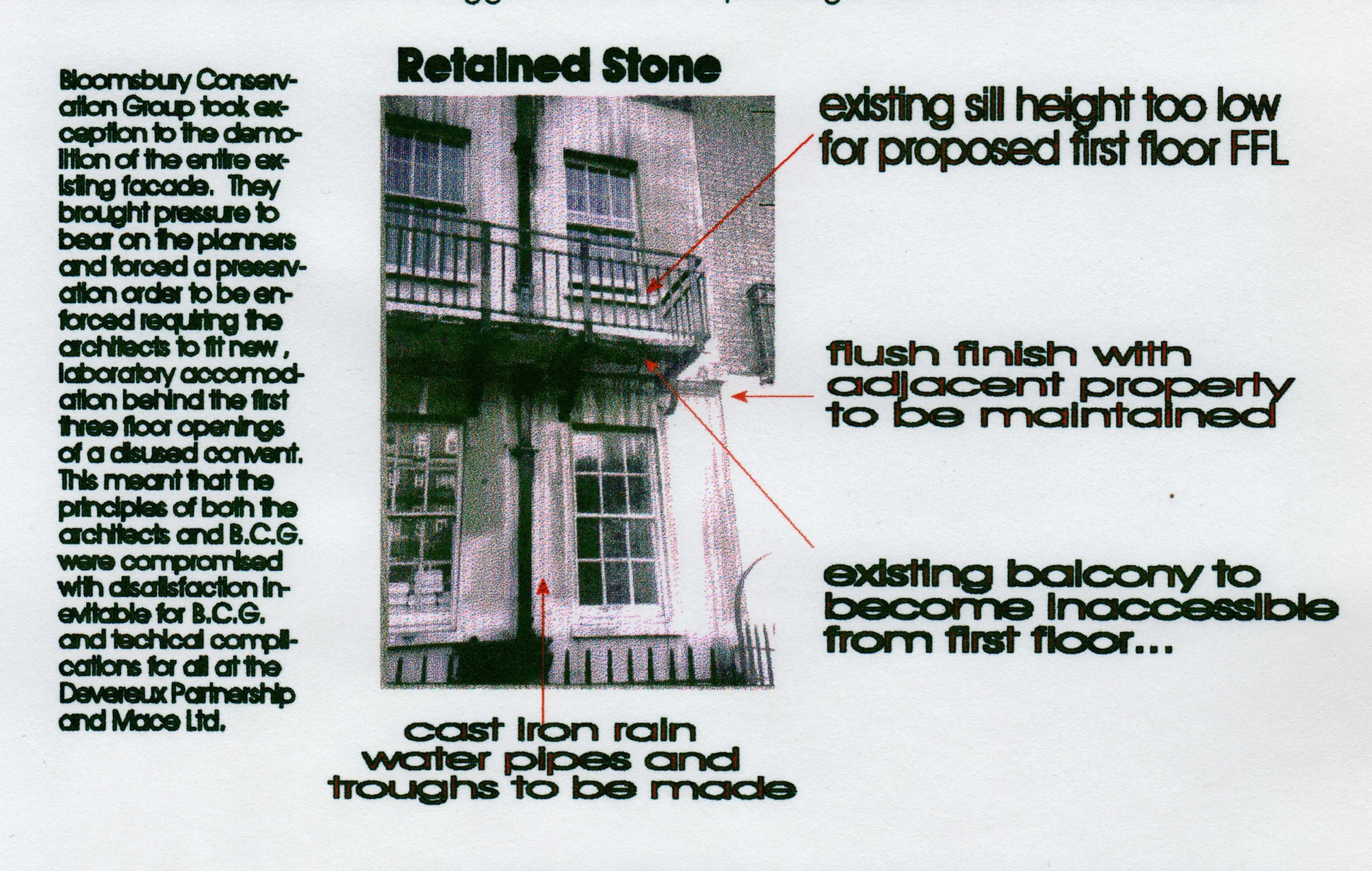
Press statements can be expected to simplify a project, but with some closer inspection into this statement, some of the complexities of the project become more apparent. The first aspect of which is most obvious, -international centre for research into the human brain- -which describes the complex use of the building but also describes the complexity of the equipment, most of which was designed in Germany. In fact the equipment manufacturer supplied the architects with information from it's UK subsidiary, information that originated from the German based headquarters. This was generally the case except information pertaining to radiation containment, which was a concrete bunker designed in the US and approved by the German headquarters to be approved by the Camden Council approved radiation protection officer, who was a nuclear physicist at University College Hospital. Another Indication of complexity of the project in the Press Statement is the expression "the centre will have access to the large patient population" and "the main entrance Is at ground floor level" ... whlch appears to show that patients will arrive at the main entrance on ground floor level and proceed into the building and have their brains scanned, In fact the main entrance is near ground floor level, 550mm below ground floor level. This condition is thanks to retention of the existing Plano Nobile, whose off street entrances both coincide with the previous building's ground floor level. If you are a patient suffering from advanced stages of Parkinson's disease, you will probably arrive to the site in a wheelchair. This requires some form of ramp to negotiate 550mm, Owing to other access requirements in the underpavement transformer room, this ramp could not be located outside the building. Inclusion of a ramp inside the main entrance was unacceptable because the client required a close circuit television security lobby inside the main entrance. This left the side door for non-ambulance access across a ramp inside the building. This ramp had to be cast into the top of the 550 ton concrete radiation shield without reducing protection from Gamma and neutron radiation. (See section above) The design and the complete replacement of the existing structure at 12 Queens Sq. and the retention of a stone plates to the first three floors is a statement in the press which simplifies the fact that nearly all of the existing building is replaced. "this level the façade is new" -which is to suggest that the brickwork will be new but the only changes in the fenestration of the upper facade are the sill heights of the slightly larger windows than those of the original building (shown below). This Is due to a four month long dispute with the Bloomsbury ConseNation Group who took exception to the proposal to change the facade to 3.5 meter bays. Preservation of the stone Piano Nobile at No.1 2 Queens Square seNed the project with more than just complications of reaching under-pavement seNices and disabled access to the building, it introduced the stones themselves which make up the wall as a found object. Once disassembled, they required safe transport from the site to safe storage and catalogued before being shipped back to the site for replacement at the appropriate stage of construction by stonework subcontractor Stonewest ltd. No. 12 Queens Square 19 Stonewest was required to do a detailed photographic & measured suNeyof the wall.Once re-erected, the procedure of building on this wall with brick to complete the elevation will produce a that will resemble a drawing that the Conservation Society's Architect drew. The comparison of the finished product to the original drawing will be a test ofthe resolve of the Bloomsbury Conservation Group. There is no comparison between the stainless steel ledger supported brickwork that occurs above first floor in the new wall and the structure of the original wall that was primarily load bearing. According to the construction programme this event will take place after the steel frame has been constructed and the in situ reinforcedconcrete base to the wall has been completed. It will then be up to the architect to decide if the stones have been replaced in the correct sequence and if any stones have been damaged, that they have been replaced with authentic Portland stone and not just finely mixed precast concrete. It is possible that this aspect of the walrs retention causes more problems than was antiCipated at design stage. The architect originally specified that .,.where lower ground floor windows needed to be blocked in that they should have been coursed through with new stones. The project manager suggested that this specification was an onerous and costly exercise for the stonework contractor who could complete the replacement more cost effectively by rebuilding the stonework as was, then fill in the original openings with stone or rendered blockwork as in a Georgian blind window. The original specification was then modified to this suggestion and the package was tendered on this basis. The existing building was constructed early this century as a convent. The upper floors contained numerous bedrooms or cells of minimal dimensions. The communal rooms were on the lower floors. The building presents it's main elevation to Queen's Square facing east. This elevation has suffered bowing due to subsidence of irs internal steel columns which are ill founded while the external walls are load bearing and supported by underpinned shared foundations. As a result the main facade has had to be restrained.
The original wrought iron balcony is in poor condition. The brackets which cantilever out of the masonry are founded deep within the wall construction and will be difficult to extract without damaging the stonework which the planners require to be replaced intact. Many other such complications would have been overcome had the architects been able to proceed with their plan to demolish the entire building and build a newwall based on three 4.5M bays or four 3.5M bays with steel windows of high standard ·W20· Critall construction. These proposals were answered by a drawing sent to the architect by the planners which was drafted by an architect associated with the Conservation Group. This proposal retained the Plano Nobile and adjusted the vertical spacing between windows of the upper stories according to new floor to floor heights of the new construction behind. Compliance with this drawing was required by the planners before any recommendation could be made by the planning officer assigned to the project by the council to the planning committee. Serving the Laboratory with access for pedestrians, gas, electricity and water would have been less difficult if planning consent had allowed a new-bulld main facade. The fact that the convent facade was retained presented enormous complications for the consultants involved with designing a way through for handicapped access, and building services. Because of the height of the Radiation shield in the lower ground floor, it was impossible to match the existing ground floor height with the proposed.


"Queen Square is a garden square in the Bloomsbury district of the London Borough of Camden, England. Queen Square was originally constructed between 1716 and 1725. It was formed from the garden of the house of Sir John Cutler baronet (1608-1693), whose last surviving child, Lady Radnor, died in 1697 leaving no issue. It was left open on one side for the landscape formed by the hills of Hampstead and Highgate.
Queen Charlotte and treatment for George III
Queen Square, Bloomsbury in 1786
The fields to the north reach as far asHampstead
In the 21st century the church of St George the Martyr 1706 at the far left is readily identifiable as are the first few houses beyond the corner of Cosmo Place now containing 'the Queen's larder'
The square was previously named Queen Anne's Square because a statue contained within it was misidentified as depicting Queen Anne. This statue is now believed to be a portrayal of Queen Charlotte, wife of King George III.
George III was treated for mental illness in a house in Queen Square towards the end of his reign. The public house on the southwest corner of the square, called 'the Queen’s Larder' was, according to legend, used by Queen Charlotte to store food for the King during his treatment.
The church, dedicated to St George the Martyr, was built following public subscription in 1706. The church's rector from 1747 to 1765 was the famous antiquary William Stukeley (1687-1765) whose rectory was next to the residence of the Duke of Powis.[1]
Late 19th Century
Built in the early 18th Century as a fashionable area by the mid 19th Century it had attracted many French refugees and the shops of sundry booksellers and print sellers and had become a favoured centre for charitable institutions including the Roman Catholic Aged Poor Society and Society of St Vincent de Paul. Gradually the mansions were turned into hospitals and other institutions.[1]
Buildings in the 20th Century
Many of the buildings surrounding the square are devoted to providing, researching and administering health care. Two hospitals, the National Hospital for Neurology and Neurosurgery (NHNN), often referred to synechdochally as 'Queen Square', and the Royal London Hospital for Integrated Medicine (formerly the Royal London Homoeopathic Hospital), make up the east side of the square. The Institute of Neurology, part of University College London (UCL), is located in the north east corner of the square. The former Institute for Public Health takes up much of the north side - the building is now used as the administrative centre for the NHNN and Institute of Neurology.
Several buildings on the west side of the square are devoted to medical research and are part of the Institute of Neurology and other departments of UCL. These include Alexandra House at 17 Queen Square which houses the UCL Institute of Cognitive Neuroscience and the Gatsby Computational Neuroscience Unit. The Wellcome Trust Centre for Neuroimaging (commonly referred to as the Functional Imaging Laboratory (FIL)) are located at 12 Queen Square. 8-11 Queen Square (Sir Charles Symmonds House) houses the Dementia Research Centre on the first floor and the Centre for Neuromuscular Diseases on the ground floor.
At the southern end of the square is the church of St George the Martyr, the Mary Ward Centre and the former Italian Hospital, now part of Great Ormond Street Hospital (whose main buildings are in Great Ormond Street, off Queen Square)."
-Narrative gratefully borrowed from Wikipedia

An unlisted early 20th Century convent adjoined and was owned by the Institute of Neurology. This building was occupied by nurses of the National Hospital and had been planned to be decanted and demolished in preparation for the F.1. L. Project. Its existence within the surrounding Preservation Area became a source of conflict. A local conservation group attempted to have the building and a large plane Tree in the rear of the site listed by the D.o.E. Neither were listed buildings but pressure from the Bloomsbury Conservation Society provoked the planners to ·suggest- that the portland stone which formed the Piano Nobile should be retained if possible- intact and if not possible, then each stone surveyed, catalogued, and rebuilt as part of the main facade which should resemble the existing building as much as possible. The drawing above describes the existing main elevation onto Queen's Square.

The appearance of a medical building is usually a major Issue to both the users of the building and the Inhabitants of the environment as well as the funding body. Medical buildings are often located in sensitive contexts. In this case, the Bloomsbury Conservation Group was happier to submit a drawing prepared by themselves for the main elevation than they were to accept the solutions put forward by the designer. Nevertheless, the architects were allowed to design the inside the building according to the wants and needs of the users of the building. This exercise resulted in months of general arrangement development that tended to frustrate the technical needs of servicing the building. Unfortunately, the strategic idea behind the design of the building had little participation by the services engineers to prevent the afore-mentioned architectural features from obstructing the flow of ductwork. Notwithstanding, such features aided in the penetration of natural light into the basement and generally improved the quality of light and space in the lower three floors.

The "before and after" analysis on this project is more dramatic when viewed in section than it is in plan. All of the usual considerations, rights of light for adjoining owners, overlook issues for rear yard neighbors, and historic preservation goals all informed the plan, even though radiation from a particle accelerator, dramatic changes in level of the interior and geotechnical constraints affecting the project due to hydrology were the more dominant technical challenges.
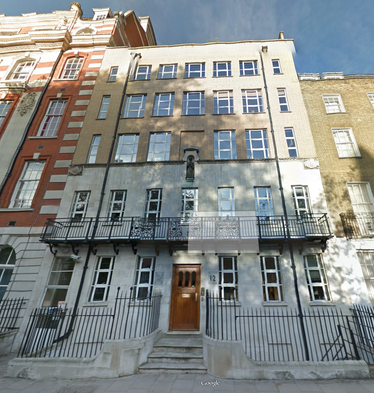
A local conservation group attempted to have the building and a large plane tree in the rear of the site listed by the Department of the Environment. Neither were listed buildings but pressure from the Bloomsbury Conservation Society influenced the planners to suggest that the portland stone which formed the Piano Nobile should be retained if possible- intact and if not possible, then each stone surveyed, catalogued, and rebuilt as part of the main facade which should resemble the existing building as much as possible.

a) The Mri Suite, b) The Pet Camera, c) The Particle Accelerator (cyclotron), d) Ancillary functions to the above, d1-the plant rooms, d2-the MRI computer room, d3-the radiographers office, d4-the preparation room, d5-the radio-pharmacy, d6-the treatment room, d7-the electrical substation, d8-the radioactive oxygen reservoirs, d9-the electronics workshop

*The magnet weighs approximately 15 tons and is founded on an independently piled raft which may not subside by more than O.06mm. It is approximately the same size as a car with a head clearance of 3700mm.
*The shielding requirements of the magnet make it possible to scan the tissue of a human being without any interference from the presence of moving ferrous objects (such as cars) or from the presence of radio frequency (such as Radio 1). Materials such as Pure Iron Sheeting shield from other ferrous objects and copper sheeting from radio frequency.
*The servicing requirements of the magnet require that the humidity of the room in which the Magnet is sited must not fluctuate more than 10 degrees degrees centigrade ... that there must be 6 air changes In that room per hour. .. and that various gasses and electricity must be supplied to the room through the various shields without compromising the integrity of those shields.
*The installation requirements of the magnet make it necessary that the wet trades of the building construction must be completed and sufficiently dry before the magnet may be delivered to the room ... also the magnet ships to the site in the form which is most compact but must still be able to fit into the room despite ifs size ...
*The effect of the magnetic field upon the environs of the laboratory and the adjacent properties means that no person wearing a pacemaker may approach the near vicinity if the magnet. That conventional computers and viewing screens may not be used near the magnet because of the magnetic media which they employ. The MRI computer room is sited next to the MRI examination room (as shown above) and encodes signals from the magnet into intelligible data which may be examined by the researchers of the laboratory. It also contains a helium reliquification plant which is used to conserve vaporized helium after cooling the magnet.

*The Pet Camera (positron emission tomographer) is a scanner which follows the path of radio-nucleids in the blood stream of the patient. The Radlo-nucleids are injected into the patient's bloodstream or by inhaled radiated oxygen. The patient receives this treatment in a special treatment room, the location of which is critical in the programming of the Pet suite.
*lfs shielding requirement involves the use of boronated block-work because of the presence of the a radioactive patient in the examination room. *It's servicing requirements are unique to the PET exam room because of exhaled radionucleids, the air extract is dedicated to this room and discharges high level above the rooftop. All other air-change requirements are similar to the MRI exam room. There are also unique service connections between the PET and the Cyclotron including a lead shield pipe which serves the exam room with radiated oxygen. There are numerous electrical servicing requirements. It's installation requirements are less demanding than the MRI scanner in that there is no extreme slab movement requirements and the machine is easier to deliver to the site.
*the effect of the radiation upon the environs of the lab is to cause restricted access to unauthorized personnel in a variety of zones within the basement level. The procedure of simultaneous scanning on both machines is made more difficult as a result of their close proximity to each other. This is due to the constraint of the size of the site and not due to a lack of programming rigor.

*the "target' is the location of the machine itself, the spot from which all gamma & neutron radiation emanate. It is responsible for the geometry of the maze which confounds the radiation from exiting the bunker and causing a health risk to people.
*The amount of radiation output by the cyclotron is considerable enough for the nuclear physicists which designed the shield to call for 500 tons of concrete to encase it.
*Materials which "slow down" gamma radiation have been specified to be admixed into the concrete at strategic points around the cyclotron such as the roof and the comers of the Maze. These materials vary but generally, a material known as "barytes" (extra high density aggregate) is being used in the roof and corners, and boronated plastic is used to line the walls of the maze.
*Geometry of the maze began as a contorted path around the mass of concrete which makes up the bunker but evolved into a simpler more usable shape which was rectangular and became so with the introduction of boronated plastiC to line the walls of the maze.
*The mass of the bunker required excessive underpinning of both the adjacent party walls to shore up the party wall foundations by an additional 2500mm.
*Foundations of the bunker consist of 24 piles spaced 2mm on centre, each with a diameter of 650mm to a depth of 1.0 meters. The frequency of these piles made access to the street for gas, electricity, drainage and water supplies nearly impossible as the bunker was located at the pavement end of the site leaving a 2.5 meter corridor under the slab to locate all of these services.
*The plant rooms of the project of which there are two, are primarily dedicated to the demands of the lower ground floor functions (described briefly above). One plant room is located directly above the fv1agnet, the other is located on the fifth (top) floor of the building. A detailed description of the plant in these rooms remains outside of the scope of this case study although certain issues relevant to the coordination of consultants by the architect may arise.
*The preparation room is where the patient is prepared for intake of radioisotope. MRI examined patients may also use this room to change clothing.

*The preparation room is where the patient is prepared for intake of radioisotope. MRI examined patients may also use this room to change clothing.

*The radio-pharmacy, sited next to the cyclone bunker is where the radioactive oxygen is first received, measured and contained for ingestion by the patient.
*The blood analysis room, sited next to the radio pharmacy is where patients blood is analysed for many different purposes related to the scanning process.

*the radioactive oxygen reservoirs are 55 gallon steel drums located in the northermost under-pavement vault where surplus radio-active oxygen is stored and contained while Irs half life is completed. After the gas has lost irs radioactivity, the gas is purged from the drums (later moved to 5th fl.) and released into the atmosphere.
*The electrical substation is where an 11,000 volt electricity main is stepped down by transformers for use by the cyclotron, the scanners, and by general office use at the laboratory. It is divided into two explosion-proof re-inforced concrete rooms which replace the 18th Century brick vaults beneath the pavement.

*The construction of these new vaults is programmed into three phases due to the fact that construction access into the site is restricted to passage over these areas. Phase 1 involved construction of the gas! water Intake room during temporary works! demolition package. Phase 2 Involved construction of the transformer room durtng foundation works package leaving existing vaults intact for construction access. Phase 3 is completed durtng subsequent stages of construction while access is gained over the cured rIc constructed phases 1 & 2. The stepped section of the building through the tree pit occurs in both north/south and east/ west planes. It also steps around the tree pit in plan so that the tree pit forms a volumetric origin which drives the simple geometry of the rest of the general arrangements so that it acts as an orienting reference for people using or visiting the building. As has already been said, it is also a source of natural light within the building which reinforces this re-orientation. How much more should a Brain Imaging Laboratory be designed to prevent the unfamiliar occupant! patient from getting lost or losing touch with his only refence to the outside world? Retention of the tight fenestration from the convent did little to sustain that reference thanks to the conservation minded, the architect has managed to achieve this strategy against all odds.


Programming usable space around a central external feature is a formal planning technique which worked well in this building's more public spaces on ground floor but also at basement level and at first floor level. The conditions around the tree pit on these other levels are shown in the drawing above. All being well with the strategic strength of the architectural concept, the omission of a mechanical & electrical philosophy from this concept leaves the building with a divisive landscape feature which enhances the conception by other building professionals that the architect is failing in his obligation to be practical toward other issues such as artificial ventilation and cibce standard luminaire selection. Nevertheless, there was little compromise on the principle of the tree pit. While it reduced in size dramatically from the feasibility study, it's location next to the garden wall meant that there was no way to bulkhead services along the wall without externalizing the ducts as in the Lloyds of London building In the City of London. It also blocked the passage of ducts in the ceiling between the control rooms so that additional ducts had to be introduced to deal with the diversion. Other additional costs of the tree pit were the addition of three reinforced concrete retaining walls to contain soil for the tree. This increased the risk of water infiltration into the basement and additional waterproofing had to be introduced to tank a retaining wall condition. It also increased the amount of external wall area which had to be made weathertight. However, the services engineer required a location for a sump pump in order to pump all of the drainage from the basement. The tree pit was chosen as the location for this feature because the building regulations did not allow a foul drain to be serviced from inside the building (let alone a clinical healthcare building), and an external manhole was required. This left little room for root structure in the tree pit and the entire exercize of designing around the tree pit in order to make the building work seemed futile as a result. It was at this stage in the project when there arose a conflict between the architectural designer and the services engineer symbolised by the sump-pump manhole and the tree in the drawing at right). This conflict revealed the powerlessness of the project manager to make a value judgement which would result in a solution to what became a lenthy conflict on site and a prolonged conflict between disciplines. In an architect lead project, leadership of the design team is fundamentalto stimulate cooperation and strategic to everyone's interests.


Neurological Research Institution associated with The Royal Institute of Neurology- Design Dev.
Architecture Firm: Devereux Partnership
Client: Royal Institute of Neurology
Site: Queen Square, London
Date of Project: 1993- 1995
Project Summary: This new building, sponsored by The Welcome Trust and The Royal Institute of Neurology- next-door-neighbor to the site of A Functional Brain Imaging Laboratory resulted in the demolition of St. John's House, an early twentieth century convent. In its place, a medical imaging lab for the study of episodic memory and other neurological conditions that utilized PET & MRI Scanning with an on-site Cyclotron (particle accelerator) and a Nuclear Medicine Lab (Blood Gas Analysis). The building probably should have been built in a green field site, away from the city- but for the critical relationship with the Royal Institute of Neurology (next door) the project was crammed into a footprint that was difficult to coordinate ground work, utilities and foundation structure and radiation protection.
John Millard's Role- I stayed with the project throughout all phases of design to construction when I joined the construction team and followed the project to construction completion as part of my RIBA Part III Case Study. There was one other (technical) architect working with me from design development to construction documents. We both reported to a principal in charge of the project.
Specific Role by John Millard: 1) Originate all CAD drawings, 2) Lead contact with Construction Management Team, 3) Coordinate Engineering Disciplines, 4) Communicate Equipment requirements from manufacturers to engineering team. 5) Produce all Schematic Phase Drawings for approval by Owner, 6) Produce all Design Development Phase Drawings for approval by Owner, 7) Produce all Construction Documentation Phase Drawings for approval by Owner/ CM.
During this phase of the project-
I had direct contact with the Neurological Scientists who were leading the research that would be pursued at the future building. The structural, mechanical, electrical and radiological engineers were also coordinated through me. Siemens, the medical imaging manufacturer, who made the cyclotron and the PET Scanner as well as the 2T MRI equipment used my desk as the point of contact for distribution of information related to the servicing and safety requirements for their equipment. I interfaced directly with the radiological safety officer on matters related to the cyclotron's standard operating procedures.
Chapter 4- Adjacent Properties
The adjacent property to the south is The Institute of Neurology (11 Queen's Square) from which all desirable neighborliness which a project architect could wish for from an adjacent property owner is available. In fact, the presence of the Institute next to the site is no coincidence according to the clienfs lead scientist who will use the Institute as a bully pulpit to advocate his discoveries and to accept willing subjects of research Into his building where they may be examined on a periodic basis. Where better to find a wealth of patlents? ... as stated clearly in the preceding press release by the architects. Never-the-less, at one point, just before ground breaking, the Institute of Neurology, allegedly prevented construction from proceeding by insisting that the charity responsible for funding the construction also purchase the site property and the existing building (which was scheduled for demolition). The trust agreed to pay for the site, and the building and the construction at the eleventh hour. Demolition was then allowed to proceed with the full cooperation of the Institute of Neurology. Their cooperation was fundamental especially as the Institute's rear premises were a necessary final destination for the alternative means of escape for the building under construction. Therefore a Right of Way had to be drawn up by the solicitors involved in the Project in order for the Architects scheme as designed to clear through building regulations. There also remained a number of structural modifications to No. 11 including a breach in the Party Wall and a Lobbied passage through accommodation in No.11 lower ground floor in order for the escape route from No.12 to the rear of No.11 to be possible from the lower ground floor of No.12. The architects scheme also depended on an external fire stair to be built on the adjacent property which would serve the upper floors of No.12 alternate means of escape. This stair, which descends seven metros from the ground floor roof terrace of No.1 2 to the rear yard of No. 11 remains undesigned and irs cost unknown. This is because of unsatisfactory proposals to the project manager by the architect in spite of repeated suggestions by the architect to negotiate a right of way for means of escape through No. 13 which already accommodates a means of escape route for the Queen's Hotel Casino. This route would not have nrequired any stair but the right of way but could have been as expensive If not more costly. This would have compounded the already difficult relationship with the adjacent property owners of No.13. They complained that the new construction would take light away from the fourth floor conservatory which they had recently completed and they threatened to withdraw their support for the project and requested compensation for their loss of light. The Party wall surveyor acting for the laboratory later discovered that the Conservatory was Illegally constructed on top of the party-wall. No action was taken in respect of this trespass so as to avoid project delay. The owners of this residential terrace immediately to the north of the site also owned the Queen's Hotel property that adjoins the site to the west. They did not object to the scheme at planning stage but appeared to be using the various inconveniences caused to them as opportunities to collect payment from the client as a result of the various agreements required by the client in order to proceed with the construction phase of the project. Issues arose which enabled the neighbors in No.13 to cause delay and increase the cost of various construction solutions. Issues such as oversailing rights by the tower crane and the nature of temporary works to the site which would support the adjacent properties. After the demolition of No. 12, the adjoining properties required temporary support. The owners of No.13 requested that flying shores which engaged their wall shound not use penetrative fixings. In return, they agreed to allow some use of their adjacent property to found scaffolding in order to greatly ease the construction of the rear extension to the new building where the magnet and the diverse selection of plans and computer rooms were located. Therefore a great deal of negotiation took place by the project managerand the party wall suNeyor in order to assure that the temporary works would not directly fix into the adjacent property (potentially damaging the party wall in the case of flying shores) and in the case of the scaffolds founding on their property, it was required that they did not obstruct the means of escape from the casino and they had to be a specialized form of scaffolding which cantilevered off of it'self inorder to reduce the number of low level obstructions. The conservatory issue is still a problem because it is Illegal, the Laboratory will have to transfer the structural support for that part of the wall away from the party wall, inboard of the boundary. Brickwork will have to be laid overhand due to the glass roof of the conservatory. These issues were constantly emerging throughout the design process and showed the architects that having an active project manager on board can liberate design professionals from the sometimes emotional and onerous conflicts with third party clients. As a result of the involvement of the project manager from the earliest phases of the project, the architects were able to concentrate on the pressing package programs which were set out by the project manager. It does appear that the delegation of these legal & contractural 'aspects of building projects creates other professional roles within the Industry in the same way that delegation of coo estimation of construction to quantity surveying profesionals. These roles have emerged to the benefit of the architect. It would be a great pity if the architect delegated so many of the roles which are required in designing a building that there was nothing left for the architect to do except act as a draughting bureau. Control over the specification of the structural build & finish of a building is increasingly influenced by the structural engineer. The management and supervision of construction on site seems to be going the way of the project manager. All that remains for the architect to do is act as the purveyor of aesthetic and programatic decisions to be instituted into the drawings. In the next section of this report, examination of the project manage(s contract with the various consultants and contractors involved will reveal if there is any need for the architect to visit the site after ground breaking in order to enforce the decisions which he has made.
Chapter 5- Why was an architect required to design a Functional Brain Imaging Laboratory?
The healthcare industry requires architects because of the specialized nature of the medical building brief. Such a brief includes highly detailed room data sheets which account for every fixture, Including specialized ironmongery, electrical and sanitary fittings as well as removable items such as waste bins and wheeled beds and couches. All these items must be scheduled In packages. Room elevations must accompany the packages detailing the location of each fitting according to the requirement of each healthcare professional who uses each room. This highly programmatic task is accomplished through painstaken work by draughtsmen and usually involves the use of computers. This is to cope with inevitable revisions to plans and elevations once they are heavily Iooded with every manner of hospital fitting and furnishing crucial to a successful patient ward. Such responsibility is unlikely to fall into the control of any other building professional except possibly the services engineer. Secondly, the appearance of a medical building is usually a major Issue to both the users of the building and the Inhabitants of the environment as well as the funding body. Medical buildings are often located in sensitive contexts. In this cqse, the Bloomsbury ConseNation Group were happier to submit a drawing prepared by themselves for the main elevation than they were to accept the solutions put forward by the designer. Nevertheless, the architects were allowed to design the inside the building according to the wants and needs of the users of the building. This exercise resulted in months of general arrangement development that tended to frustrate thetechnical needs of servicing the building. Unfortunately, the strategic idea behind the design of the building had little participation by the services engineers to prevent the afore-mentioned architectural features from obstructing the flow of ductwork. Notwithstanding, such features aided in the penetration of natural light into the basement and generally improved the quality of light and space in the lower three floors.
Secondly, the appearance of a medical building is usually a major Issue to both the users of the building and the Inhabitants of the environment as well as the funding body. Medical buildings are often located in sensitive contexts. In this cqse, the Bloomsbury ConseNation Group were happier to submit a drawing prepared by themselves for the main elevation than they were to accept the solutions put forward by the designer. Nevertheless, the architects were allowed to design the inside the building according to the wants and needs of the users of the building. This exercise resulted in months of general arrangement development that tended to frustrate the technical needs of servicing the building. Unfortunately, the strategic idea behind the design of the building had little participation by the services engineers to prevent the afore-mentioned architectural features from obstructing the flow of ductwork. Not withstanding, such features aided in the penetration of natural light into the basement and generally improved the quality of light and space in the lower three floors.
Thirdly, there was the need for someone to defend the client from the decay of quality through conflict of interest in the project. Namely, changes to certain construction applications (such as water proofing) to achieve a less expensive solution was in the architects opinion a false economy. The water-tightness of the building was the architecfs responsibility, and with £25M of medical scanning equipment In the basement, the architects took this responsibility seriOUsly. Nevertheless, the water proofing system specified to tank the basement was overruled by the project manager and the structural engineer because of a combination of cost and technical consIderatlons ... it had never been used by those consultants. The rejected system had been used by the architects on a £25M wing of the Notional Hospital of Neurosurgery on the opposite side of Queen's Square and British Standards called for cavity wall tanking in the situation such as the water table that we had on site. For reasons unknown to the author, a firm position on this issue was not taken by the architects when confronted by the two disciplines and a highly elastic waterproof membrane which could accommodate movement in the building was · used . to to,Qk the basement instead. (see minutes 1 Dec 1993 in appendix two calling for the architect to produce a performance specification for water-proofing) The project manager used the performance specification to invited tenders from waterproofing manufacturers who were able to provrde warrantees for their products performance to try to put the architecfs mind (and indemnity policy) at rest. However, upon closer examination of the manufacturer's warrantee, economic losses such as moisture penetration to the £25M worth of medical electronics in the basement were not covered. The architecfs role as quality controller on behalf of the client was frustrated by the Project Manager's contractual relationship with the subcontractor. In the contract nthe project manager takes on a role that is ill-defined in the contract but would nappear to give him the power to redesign aspects of the building to suit. In the first appendix of this report is a copy of the project manager's contract called "TRADE CONTRACT FOR USE IN CONNECTION WITH A PROJECT AT 12, QUEEN SQUARE, LONDON WC1" (hereafter known as "PMC"). This is a description of the relationship between the project manager and the various subcontractors who successfully tendered to build the respective packages. In the definitions of the contract on Page 1 is a definition of the word "Design Ie Construction Manager" which reads as follows:
"Design & Construction Manager" means Mace Limited whose principle place of business is 7 Plough Yard, London, EC2A 3LP, or any other person notified in writing by the Client to the Trade Contractor from time to time." -PMC Other references to "Design & Construction Manager" include: "3.6 The Design & Construction Manager may at any time instruct the Trade Contractor to comply with any such instruction without providing the said estimates or in the absence of agreement of the same, in which a fair and reasonable adjustment to the contract sum shall be made having regard to any applicable Schedule of Rates or Pricing Schedule. This is to describe how the trade contractor should comply in the event of a variation but according to the "Concise Encyclopaedia of Architectural Practice" by David Chappell and Ray CeciL ..
"A variation is any change in the work specified in the contract or the conditions under which it is to be carried out. Most forms of contract stipulate that no variation shall vitiate the contract and provide rules for valuing the variations. There are additional provisions within the JCT forms for recompensing the builder if the stated methods of valuation do not adequately compensate him. Notwithstanding the "no vitiation" clause, a variation can be of such a nature that it changes the scope of the contract. In such cases the instruction itself is invalid and is outside the architecfs authority." as in JCT Standard Form of Byildinp Contractl98Q Edition, hereafter known as "JCT 80"
"4-1 The Contractor shall comply with all instructions issued to him by the Architect in regard to any matter in respect of which the architect is expressly empowered by the Conditions to issue instruction; save that where such instruction is one requiring a Variation within the meaning of clause 13-1-2 the Contractor need not comply to the extent that he makes reasonable objection in writing to the Architect to such compliance" -JCT -80
Following these clauses within PMC & JCT 80 are corresponding clauses which entitle the client to "employ others" to perform the variation if the subcontractor has not compiled with the variation within five working days. What appears to be the difference between the two contracts is a fundamental expectation about the extent to which the design of the building is complete at the time of going to tender. In the case of the PMC the expectation is that the design is not complete at the time of tender and that the contractor should expect a culture of variation within the job. This is due to the fact that the packages of drawings that were issued for tender were correct at the time of issue. However, they were issued before the rest of the design packages were complete thus allowing the exercise of costing the construction to go on with perceived certainty. However, by the time construction begins, the consequences of completing other packages has not been registered by the subcontractor in his package of work before he has started or worse, after he has started. At this point, it may be possible that the design and specification of the consequent packages may suffer in order to control escalating costs.
In the case of the JCT 80, the expectation is that the architect is finished designing the building to the best of his knowledge because of the increased time which has been spent preparing an accurate record of the design. Indeed, the architects code of conduct requires that he do so ... " A registered person who intends to maintain his integrity so as to deserve the respect and confidence of all those for whom or with whom he may work in his capacity as an architect will assure himself that information given in connection with his services is in substance and presentation factual and relevant to the accession and neither misleading nor unfair to others ... " Sadly, if the construction industry is to be believed, this aspiration is seldom achieved by an architect (depending upon the project and upon the client).
The approach which the fast track project manager makes is entirely honest whereupon he admits that eventualities accur on projects where the design is intended to be complete, how much more on a project which is incomplete at the time of going to tender? If a builder is tendering for a fast track project then he will prepare himself to comply with directions from the design & construction manager in good faith that such eventualities will be recompensed on the basis of "any applicable Schedule of Rates or Pricing Schedule."
This is not how variations are dealt with on site however. Many variables are dealt with in a manner similar to JCT 1980. Subcontractors and the Site Agent for the Project manager rarely operate according to the Mace Contract with respect to variations, but rather work within a JCT80 culture. The variation is fi~st considered and priced by the subcontractor (and that price must be agreed with the Design & Construction Manager) before any work is carried out. If the price is not agreed, then a less costly construction detail is put forward by either party and agreed before any work is carried out. Not withstanding, this process can be expected to result in a more conventional detail (and possibly less elegant) than that which was originally the subject of the variation. Finally, the agreed variation is sent to the architect for approval that in the eyes of many is considered a rubber stamp exercise. The architect will normally concede provided that the variation (which may have been initiated by the design & construction manager) is coordinated with the rest of the scheme.
In the case of A Functional Imaging Laboratory, it has been observed that the interests of the subcontractor are best served by well coordinated information. They are also well served by programming the construction so that trades are not tripping over each others feet because of too many tasks being executed simultaneously by the design and construction manager. This problem is endemic on a fast track contract. At last notice the construction foreman was concerned enough about the problem that he alerted the health & safety inspector to make a spot inspection. This was in order that the project management company might be forced to comply with regulations regarding a number of safety issues ... as can be seen from a copy of the inspectors report shown here and below:
As a result of the inspection, the project management employed the scaffolders to provide proper gangways and to cable off unsafe areas. The bricklayers were paid to hold off while certain aspects of their access provisions were made good and their working area was cleared of all stored steelwork. Nevertheless, the following day the crane driver fell down the cage ladder and had to be hospitalized and a steel erector fell two storeys onto profiled metal decking and returned to his post bolting the steel frame together after a breather. It seems that safety standards are no guarantee against carelessness ...
In this analysis, funds from the project management to improve site access for operatives in the interest of safety were only forthcoming after their own construction manager called in the health and safety inspector for fear that someone might be seriously injured. If this is the level of commitment to site safety, what of the commitment to build quality and finish?
Chapter 6- Cost Over-runs
Early in the project, as the feasibility study was complete, the "in house" Q.S. on the Project Manager's side prepared initial costings which were underestimated. The revised costings at scheme design stage increased by as much as 30%. The increase warranted a "value engineering" inquiry/ workshop held by the project manager before going to tender. During this time, the events which had taken place since the planning consent were accounted for by each of the disciplines who experienced changes in their part of the design. The reputation of Architect Led Projects recieved a boost when the project management team which had come to grief over the unexpected cost overruns conceded that all of the increased costs of the scheme were justified. The client had to be notified that the project was suffering an overrun of at least 20% in cost, and the program had been set back by three months out of a twelve month period. The Welcome Trust responded by assigning a quantity surveyor from one of their own project teams to A Functional Brain Imaging Laboratory. This would normally not have happened on a Welcome project with a value less than 20M. The project management team then reported the history of the Project Budget directly to the Welcome quantity surveyor until all packages had been tendered. It is fortuitous for the Project Manager in this respect that the contract was not a fixed price contract. Were it not for the scientific urgency of the project it might well have been run under JCT 1980. The project had to be completed before competing scientists in other countries made breakthroughs in understanding & treating Parkinson's Disease. The project might well have been completed without a fast track project manager and a bespoke contract which allowed an early start on site with a stated but apparently flexible cost ceiling. One of the advantages of healthcare architecture is the well endowed nature of healthcare clientele.
The cost overruns began with a planning conditon that required the existing stone piano nobile be replaced. The cost of this was valued at £250,000. Additionally, there appeared to be a change of the escape requirements of the upper floors by the Building Control Officer and an external stair was later required due to the building's classification under "The Hospital Technical Memorandum" published by HMSO. This differed from the original classification under "~ Building Regulations" also published by HMSO. The addition of the external stair cost £---------. The building fell into a grey area of the regulations because it was primarily a research facility treated as an office by the building regulations in the upper four floors. The presence of examination rooms on the first floor and a highly populated seminar room on the fourth floor changed the b.c.o.'s view of the escape requirements after the initial co stings were calculated. Another cost overrun occurred when the equipment manufacturer Siemens PIc. later required the radiation shield to be increased in mass & complexity by a factor of four. This dramatically effected the underpinning works to adjacent properties by doubling the depth of the underpinnings to two metres. The frequency of piles was increased under the bunker and the ground works package and the piling contract suffered a £100,000.00 increase over initial costs.
On the mechanical side, Siemens later specified that the radiation bunker mu~ be air conditioned. Until this time, it had not been thought that air should be supplied into the target area through eight foot thick steel reinforced concrete walls without increasing the risk of radiation escaping into the environs of the Laboratory. However, Siemens reassured us that tried and tested technology from air conditioning containment vessels on nuclear submarines was available. The additional cost of this is still not certain. A number of other factors effected the cost overuns of the project such as the inaccessibility of high voltage current in Queen's Square. Therefore, a private transformer substation had to be built under the pavement in explosion proof reinforced concrete vaults. Access to these vaults for delivery and installation of the transformers became a source of controversy during the design stage of the project. The services engineers differed with the architect who believed that transformer access should be through the roof via a service hatch in the pavement ... drawings were prepared and sent to L.E.B. directly. This access meant that underpavement services to the square might have to be disconnected for an unknown period of time requiring consents and additional cost. The services engineers were upset that L.E.B. had been contacted by the architect and a design for the vaults discussed without their approval because they wanted to access the vault with the transformer differently- by delivery through the light well and laterally loading the transformer in through the entrance of the vault. L.E.B. reviewed both schemes and preferred the architect's proposal. However, as construction evolves on the site, it would appear that the top of the vault has been cast without the opening for the hatch. It also appears that it may not be necessary to shut off the under-pavement services because of the tolerance that exists after excavation.
Chapter 7- Scheme Design Stage
It was apparent from the start of the F.l.l. Project, that much of the budget for the construction would be absorbed by cMI engineering works. The concrete radiation shield for the cyclotron proved to be the source of much expense tJnderground. From the Architecfs point of view, the funds for assuring procurement of quality materials, finishes and fabrication rested on insuring that the cMI works to the foundations were not over-designed, and that design of the radiation shield itself was not unduly conseNative without risking the general public's health and safety. This view was due to the constant budgetary reassessment which the project manager supervised. None of the project team members who were signed up with the project manager were qualified to calculate the thickness of mass concrete required by the radiation shield. The shield had to contain neutron and gamma radiation which the manufacturer calculated would be emitted by the cyclotron. The manufacturer (Siemens) made these calculations available to anyone who wished to design a shield for the cyclotron. In August 1993, Siemens suggested a shield which they accepted no responsibility for (shown below). Throughout the critical initial costing period, the entire project team were led to believe that the radiation shield posed no inordinate cost to the construction. It appeared that the shield was simply a reinforced concrete wall which would pose some additional cost but would not exceed wall thickness of 300mm. Therefore, the planning submission went in to the local authority (a Mnuclear-free" zone) with this quite inconspicuous profile having the room title on the drawings "oxygen generatorM. The Quantity SUNeyors at the Project Manage(s office estimated the cost of the room as an essentially insignificant sum and the engineers did not consider the room as a threat to their underpinning strategy. These assumptions later were proved to be ill-founded as the nuclear scientists at Siemens Pic slowly realized that they had drastically under-estimated the radiation output of the cyclotron in their design of the radiation shield.
The design "suggestion" for the shield was then passed on from Germany to the scientists in the U.S. In the transfer of information between continents, significant -details regarding the nature of the site were omitted. The fact that the site was a congested, sensitive, central London square with neighbouring grade 1 listed buildings flanking the site to the north and routh party walls was omitted and the Siemens scientists in the USA assumed that the site was a green-field site. This breakdown in communication should have been addressed by the project manager. The fact was that the people who were designing a 550 ton part of the building thought t~at the site was a green field. All communication with Siemens had to go through the project manager. The U.S. Scientists recalculated the neccessary thickness of concrete and produced aconservative bunker with six foot thick walls, ceiling and floor. This new bunker also contained a maze which compromised the workspace inside the bunker, around the cyclone itself in order to prevent the escape of gamma radiation. Initially, the defacto nature of events which surrounded this second design meant that the design team accepted it without question, and with much amazement. However, as the repercussions of the sheer mass of the bunker began to manifest, action to redesign the scheme and the bunker gathered momentum. By the end of November, the full implications were known. Complaints about the bunker's mass were telephoned through directly to Siemens as consultants broke ranks with the project manager's chain of command and communication. One architect telephoned the nuclear physicist responsible for designing the cyclotron and suggested a lithium based material of a soap-like density and consistency to replace the mass concrete in the bunker in order to reduce mass and thickness of the concrete walls. Her immediate response was why was the Project Manager not handling this aspect of the query and that the shield as proposed was only a suggestion and Siemens could not take any responsibility for the design. Consequently, as demanded by the project manager's drawing programme, this architect had to incorporate the suggested bunker (shown above) into the plans of the proposal and in doing so, moved the bunker vertically so that the roof of the bunker was equal to the finished floor level of the ground floor and eliminated the superfluous structure which
the engineers had spanned over the top of the bunker. This had the effect of reducing the depth of the 2000mm underpinnings to the party walls by 300mm. It soon became clear that any effort to reduce the depth of the bunker had the net effect of reducing the cost of the substructure. When it became impossible to move the bunker within the scheme any more, access ramps began to be shaved off of it, slightly reducing it's weight. Before long, the architect invited Ministry of Defense Subcontractors to design team meetings to lecture the design team on the merits of containment design in the confined space of a nuclear submarine. Their solution was to use the lithium based material called ·Premedex" which replaced approximately 1 . 5 cubic metres of concrete radiation protection with 1 cubic metre of Premedex protection for one tenth of the mass of concrete. Needless to say, at £3000.00/ metric ton of Premed ex, the Project Manager quickly calculated that the concrete was 50times cheaper than Premed ex even if the Premedex was only 10 times lighter. There were still savings to be made in the design of the steel tail-down cantilevered in-slab support system which the structural engineer used to increase the distance from the perimeter piles to the party wall edge. The detailing of this complex structure was already well advanced according to programme so that the ground works package could go to tender on schedule. The design of the steel members in the slab were proportional to the excessive loading which the concrete in the eastern end of the foundation posed due to the bunker. Savings could have been found in the excessive number of piles which had been planned to support the bunker. Nevertheless, the following letter to Siemens Pic.
Nevertheless, the following letter to Siemens Pic. had the effect of urging Siemens to redesign their suggested radiation shield.
After the SIemens package was Issued, and all requests to modify the radiation shield had been made by both the architects and the structural engineers, scheme design proceeded on the basis that there would be no modifications. WIthout Informing the design team, SIemens was quietly going about redesigning the US version of the shield at the Medical Engineering Headquarters at Ehrlangen. During this interlude, several packages were tendered wtthout benefit of changes which the engineers In Germany were preparing in the new shield design. The steel work package with the Tall-down system went out to tender, the groundworks package went out without moolfiCatlon,the piling package and the equipment package all became construction documents with out anyone aware that variations would have to be seNed to the successful
tenders In order to reduce the cost of the foundations. The increased costs which had accrued as a result of the post feasibility changes to the radiation shield and the stonework retention were beginning to worry the client bOOy and a special QS was appointed by the Welcome Trust to help rationalize the Increases which were being reported to the Trust on a monthly basis. The effect of this was a series of Project Management led "value engineering workshops· which resulted In improved understanding of the crisis by all parties. The architects view of the project became one of ·status quo· where the usual cost overruns experienced by architects on building projects were now being experienced by the project manager. These cost overruns were noN being experienced by the project manager partly because of the fragmented command and communication structure of the project. The severance of the architect from the client and employment by the Project Manager meant that all of the cllenfs Instructions to the architect, all of the perceived Interests of the client and all of the Interests of the architecture had to be filtered through the Project Manager. In the case of this project, the cMI engineering background of the Project Manager assured success and quality to the heavy works, but a uncoordinated relationship between each of the other diSCiplines Including the equipment manufacturer. This incoordination is one source of cost, the delay and the lack of cooperation between the services engineers and the rest of the team Is another. Architect led teams also have this element of malfunction but the addition of yet another discipline seems only to exacerbate the problem. When the SIemens scientists in Ehrlangen had completed their calculations for the new radiation shield they called a meeting at their UK headquarters In Bracknell. They still had not announced the new radiation shield. All of the consultants and the project manager were present at the meeting. They announced that they had redesigned the radiation shield using liquid paraffin as the hydrogen rich and economic gamma ray absorber which would reduce the amount of concrete In the bunker. this propa;al was greeted with some surprise by all In attendance because of the combustble nature of liquid paraffin which they proposed to fill large cavities in the concrete walls and ceiling. Nevertheless, they were able to Increase the amount of space where there was once mass concrete. According to Siemens, the safety of the cyclone operator was jeopardized by the cramped conditions around the machine Itself. If the operator collapsed while the door to the machine was open then it would be Impossible to reach the Injured party without causing further Injury- a reason (possibly the only reason) which none of the consultants had considered for redesigning the shield.
Search for an alternative material to paraffin began immediately. It was suspected that The Fire OffIcer and the Building Control Officer might object to the use of a flammable material as radiation insulation. It's encasement within the concrete also worried the project team because of the explosive potential of the detail suggested by Siemens PIc (rome thought the Project Manager should remind them of the impending D Day Commemoration) ... The consultants and the project manager ruled out ·PremedeX- because of It's high cost. Enquiries to British Nuclear Fuels and Sellafield turned up a new material which was inexpensive and eaS{ to install. It was Boronated Plastic and It shipped In 25mm thick sheets. Calculations by the manufacturer determined that It was sufficient to replace liquid paraffin, furthermore, It could be applied to the Inside of the mass concrete as a lining. This meant that no cavities would have to be cast into the concrete and the Inside of the bunker would have a handrome finish of plastic sheen with multicoloured speckles of boron making it the most fashionable cyclotron enclosure in the world. This is not to say that construction of the bunker would be eaS{. As It happens, the ground works package which the bunker fell into should have been complete some six weeks ago and the package is bound to suffer further delay as there remain a number of unfinished elements such as the r.C. upstand parapets and the r.c. retaining wall around the tree pit. As to the additional cost of this package due to the bunker, It should be ~Id that the architects spearheaded the effort to assure a rigorous design for the bunker so that the interests of the client were best served In terms of his brief and use of the ~Iotron as well as the best value for money. Unfortunately, as has already been ~id, the over-represented cMI engineering disciplines on the Design Team resulted in addressing the problem with over-deslgned solutions rather than lateral thinking and consideration of how the other packages might suffer financially from reinforcing an over-piied raft with 254x254mm U.C. sections.
After the SIemens package was Issued, and all requests to modify the radiation shield had been made by both the architects and the structural engineers, scheme design proceeded on the basis that there would be no modifications. WIthout Informing the design team, SIemens was quietly going about redesigning the US version of the shield at the Medical Engineering Headquarters at Ehrlangen. During this interlude, several packages were tendered wtthout benefit of changes which the engineers In Germany were preparing in the new shield design. The steel work package with the Tall-down system went out to tender, the groundworks package went out without moolfiCatlon, the piling package and the equipment package all became construction documents with out anyone aware that variations would have to be seNed to the successful tenders In order to reduce the cost of the foundations.
The increased costs which had accrued as a result of the post feasibility changes to the radiation shield and the stonework retention were beginning to worry the client bOOy and a special QS was appointed by the Welcome Trust to help rationalize the Increases which were being reported to the Trust on a monthly basis. The effect of this was a series of Project Management led "value engineering workshops· which resulted In improved understanding of the crisis by all parties. The architects view of the project became one of ·status quo· where the usual cost overruns experienced by architects on building projects were now being experienced by the project manager.
These cost overruns were now being experienced by the project manager partly because of the fragmented command and communication structure of the project. The severance of the architect from the client and employment by the Project Manager meant that all of the cllenfs Instructions to the architect, all of the perceived Interests of the client and all of the Interests of the architecture had to be filtered through the Project Manager. In the case of this project, the cMI engineering background of the Project Manager assured success and quality to the heavy works, but a uncoordinated relationship between each of the other diSCiplines Including the equipment manufacturer. This incoordination is one source of cost, the delay and the lack of cooperation between the services engineers and the rest of the team Is another. Architect led teams also have this element of malfunction but the addition of yet another discipline seems only to exacerbate the problem.
When the SIemens scientists in Ehrlangen had completed their calculations for the new radiation shield they called a meeting at their UK headquarters In Bracknell. They still had not announced the new radiation shield. All of the consultants and the project manager were present at the meeting. They announced that they had redesigned the radiation shield using liquid paraffin as the hydrogen rich and economic gamma ray absorber which would reduce the amount of concrete In the bunker. this propa;al was greeted with some surprise by all In attendance because of the combustble nature of liquid paraffin which they prq:>OSed to fill large cavities in the concrete walls and ceiling. Nevertheless, they were able to Increase the amount of space where there was once mass concrete. According to Siemens, the safety of the cyclone operator was jeopardized by the cramped conditions around the machine Itself. If the operator collapsed while the door to the machine was open then it would be Impossible to reach the Injured party without causing further Injury- a reason (possibly the only reason) which none of the consultants had considered for redesigning the shield.
Search for an alternative material to paraffin began immediately. It was suspected that The Fire OffIcer and the Building Control Officer might object to the use of a flammable material as radiation insulation. It's encasement within the concrete also worried the project team because of the explosive potential of the detail suggested by Siemens PIc (rome thought the Project Manager should remind them of the impending D Day Commemoration) ... The consultants and the project manager ruled out ·PremedeX- because of It's high cost. Enquiries to British Nuclear Fuels and Sellafield turned up a new material which was inexpensive and eaS{ to install. It was
Boronated Plastic and It shipped In 25mm thick sheets. Calculations by the manufacturer determined that It was sufficient to replace liquid paraffin, furthermore, It could be applied to the Inside of the mass concrete as a lining. This meant that no cavities would have to be cast into the concrete and the Inside of the bunker would have a handrome finish of plastic sheen with multicoloured speckles of boron making it the most fashionable cyclotron enclosure in the world. This is not to say that construction of the bunker would be eaS{. As It happens, the ground works package which the bunker fell into should have been complete some six weeks ago and the package is bound to suffer further delay as there remain a number of unfinished elements such as the r.C. upstand parapets and the r.c. retaining wall around the tree pit. As to the additional cost of this package due to the bunker, It should be ~Id that the architects spearheaded the effort to assure a rigorous design for the bunker so that the interests of the client were best served In terms of his brief and use of the ~Iotron as well as the best value for money. Unfortunately, as has already been said, the over-represented engineering disciplines on the Design Team resulted in addressing the problem with over-deslgned solutions rather than lateral thinking and consideration of how the other packages might suffer financially from reinforcing an over-piied raft with 254x254mm U.C. sections.
This problem was compounded by a reluctance by the Project Manager to criticize Siemens Pic., as the greater interests of Mace Ltd. would have been served by compliance and acquiescence rather than objective consideration of the undertaking which the client had set out to accomplish. Not one consultant on the design team would differ with the view that a greenfield site In Hounslow or Greenford would serve the project by haMng the cost of the ground works package, the cost of land, and eliminate the retention of the Portland Stone as well as greatly simplifying construction access and method. It is not within the scope of this project to detail the construction methods used or how they were complicated, but the following series of photos conveys some of the access difficulties as well as the intensity of construction which was required of this 600 square meter site:
Preparing the site for a 550 ton concrete bunker meant intensive piling under the bunker and frequently along grid lines. One concern which the structural engineer had was that the excessively weighted east end of the building would result in negative loading at the west end. This required use of the weight of the external walls to be linked into the substructure using cantilevered taildown beams which would cantilever the external walls off of piles located along the perimeter of the site. This meant that piles would have to be drilled exceedingly close to the party walls. Access to these areas was Impossible with a conventional pile driver which required great head height. The temporary works impeded the movement of such plant and required the use of gravity drop piling which is time consuming and costly.
Ultimately, the client is responsible for the choice of the site. The structural engineers designed a complex -belt & braces- foundation system and delivered a viable temporary works package and program which assured all involved (especially the adjoining owners) that the rights to support were under control and that the construction of the building could proceed without to many hindrances as a result. The final outcome is yet to be known since the building is only half complete by this stage but thus far, every assurance has been taken by the design team and at great expense to the client ...
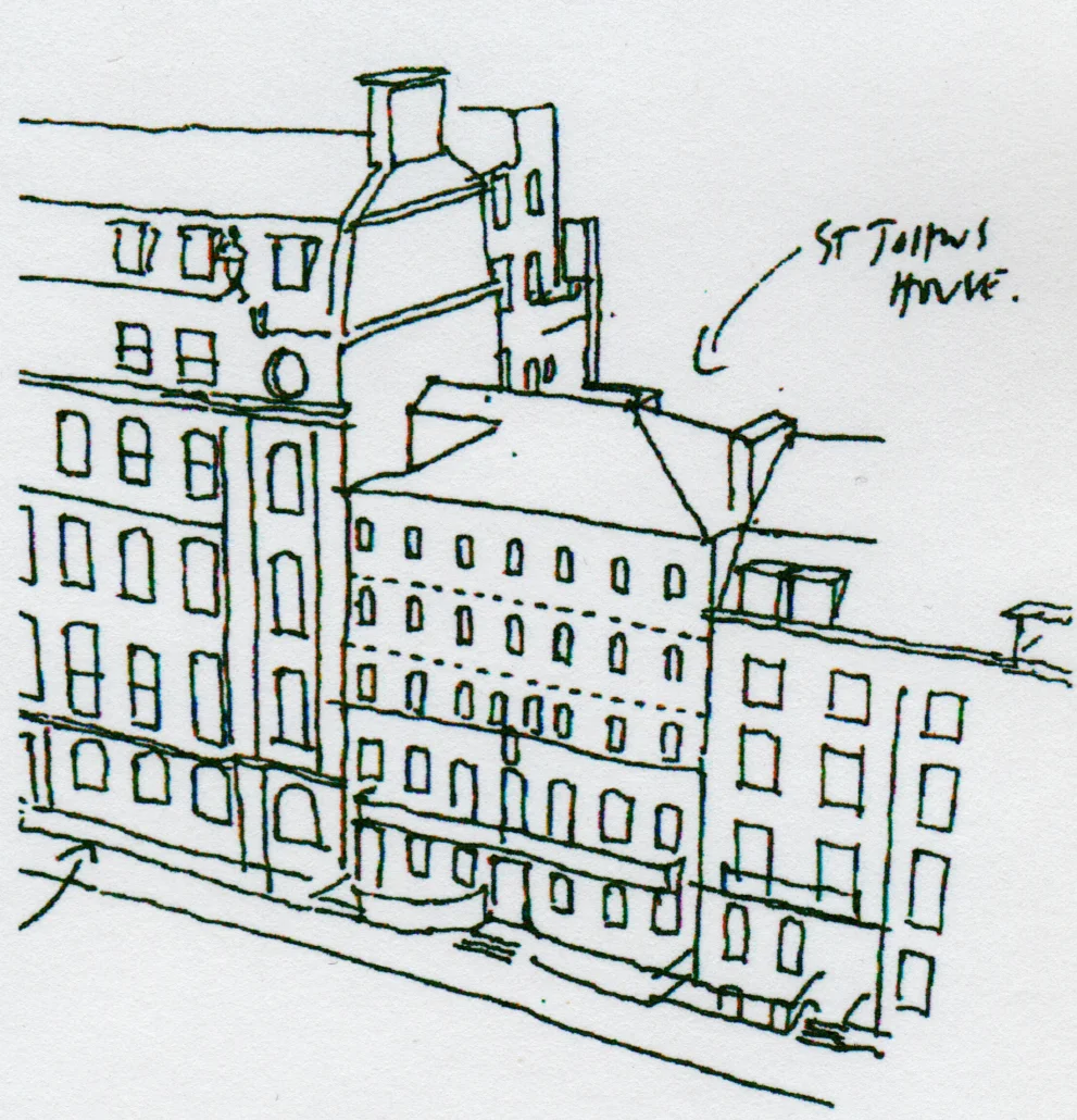


A stepped section in the building forms a non-negotiable chasm in the relationship between main building and the services extension where most of the heavy plant is located.
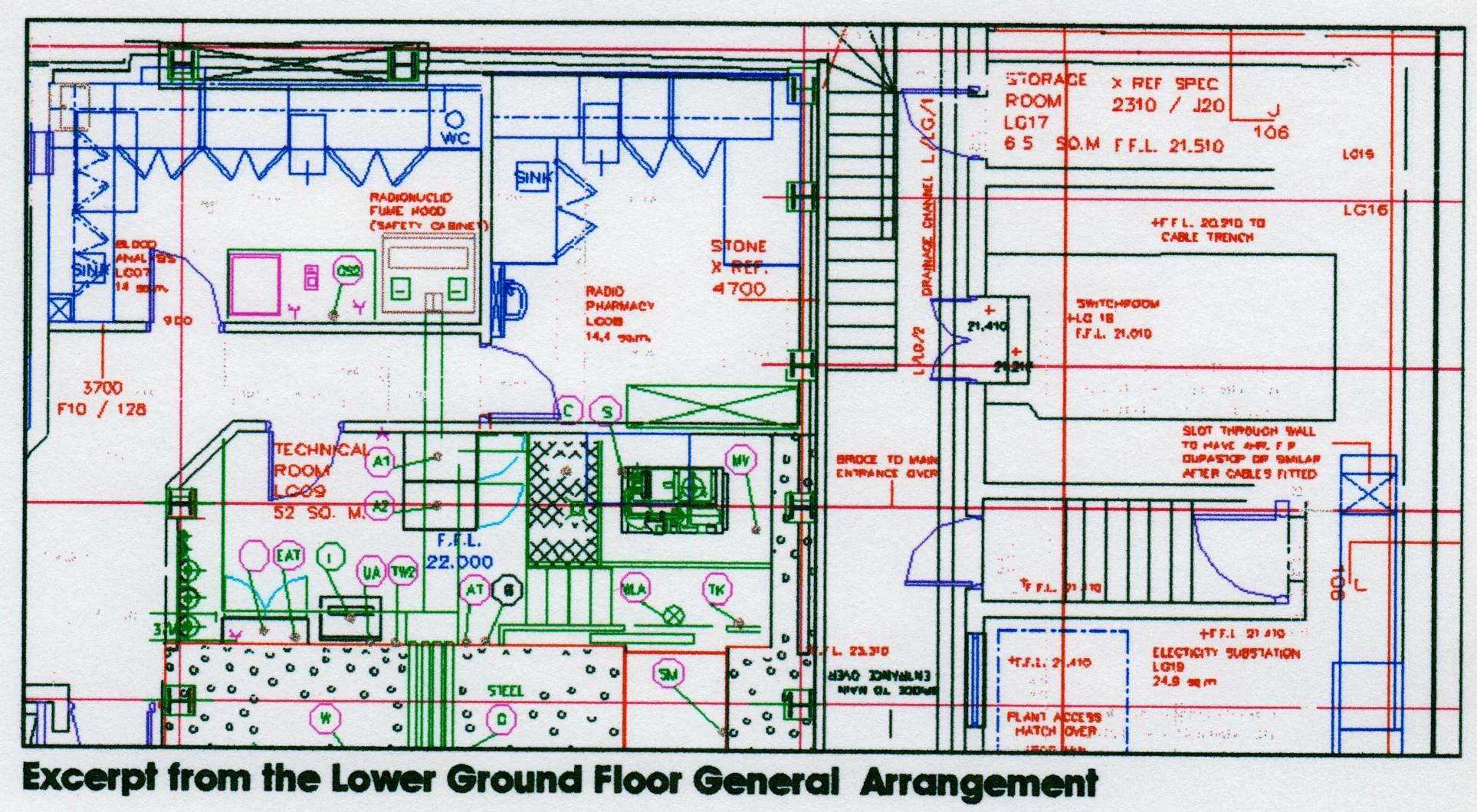
An excerpt from the lower ground floor general arrangement indicates a need for some coordinating role between the architect, manufacturer of the equipment, the structural engineer, the mechanical and electrical engineer and the client- all of whom issue information independent of one another. ShoUld the architect perform this role or should the project manager? Is the detailed information produced by the architect in an information vaccuum unless he is performing this role? Should the architect also perform the role of a project manager in order to be effective in coordinating information? Or has a new role evolved on the complex project, one which combines the authority of both roles with a design & construction managing role which carries through the drawing office on to the construction site with full contractural control over all construction?
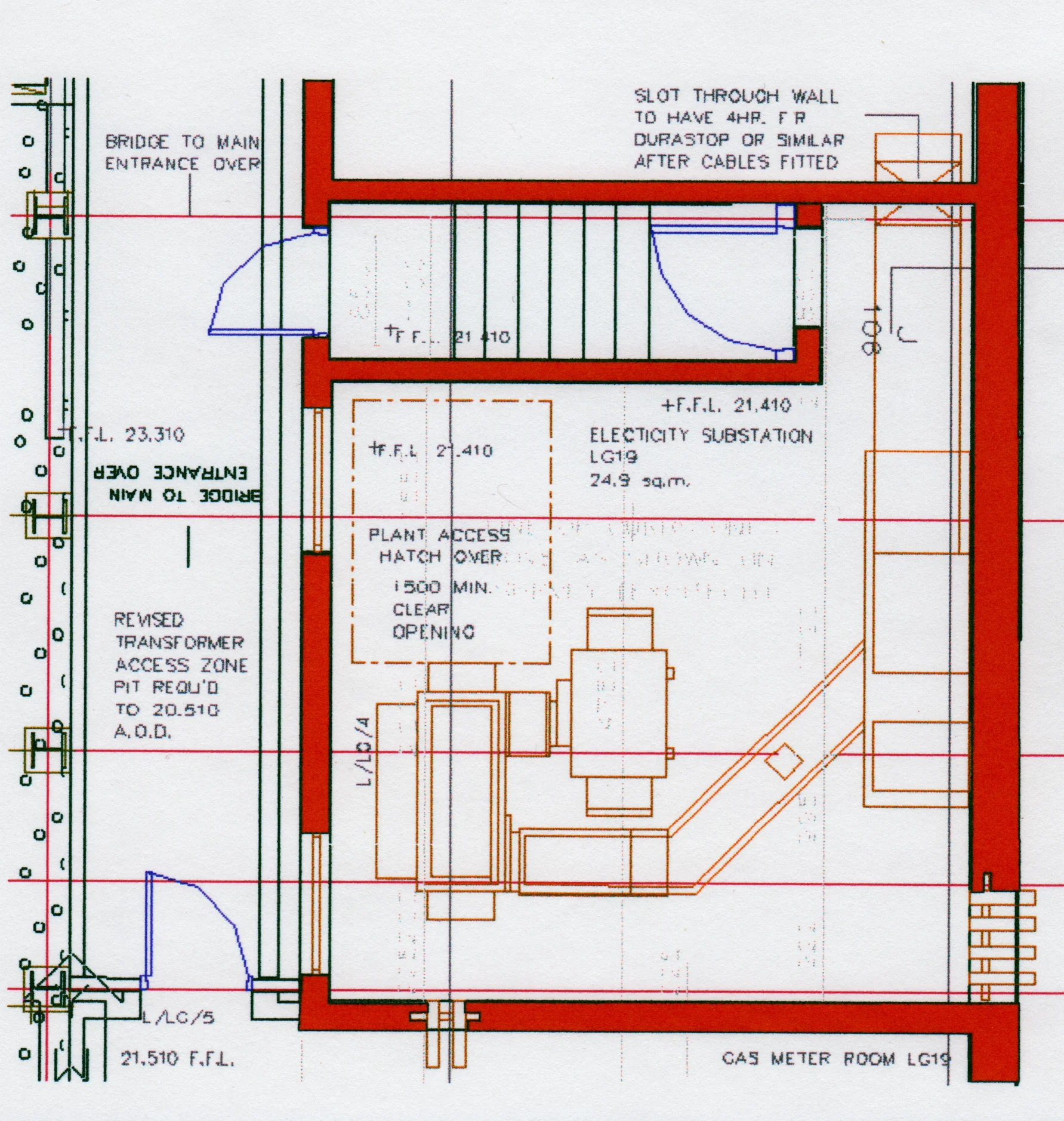

The 36 piled foundations required to support the 500 ton cyclone bunker (also an unforeseen cost) tipped the budget over by an order of magnitude largely because of the fact that at the time the project was designed, there were only four PET scanners in the world.


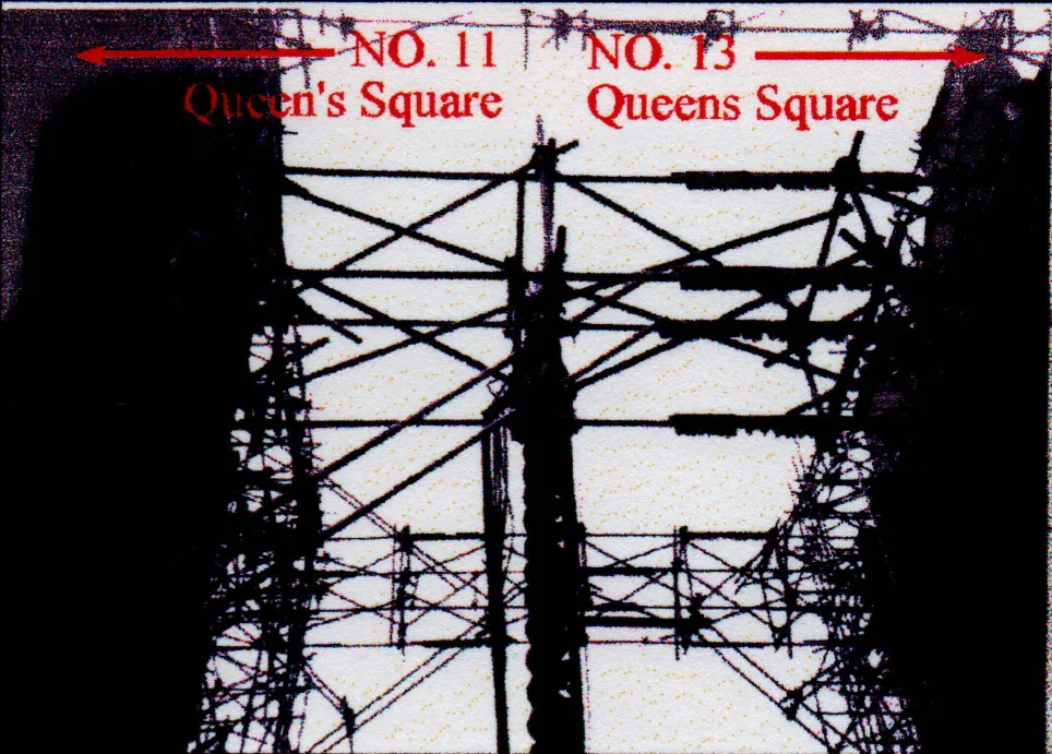


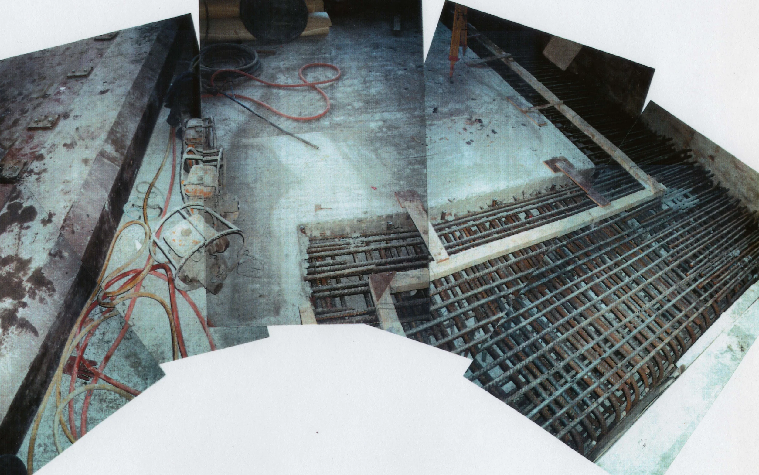


Neurological Research Institution associated with The Royal Institute of Neurology- Construction
Architecture Firm: Devereux Partnership
Client: Royal Institute of Neurology
Site: Queen Square, London
Date of Project: 1993- 1995
Project Summary: This new building, sponsored by The Welcome Trust and The Royal Institute of Neurology- next-door-neighbor to the site of A Functional Brain Imaging Laboratory resulted in the demolition of St. John's House, an early twentieth century convent. In its place, a medical imaging lab for the study of episodic memory and other neurological conditions that utilized PET & MRI Scanning with an on-site Cyclotron (particle accelerator) and a Nuclear Medicine Lab (Blood Gas Analysis). The building probably should have been built in a green field site, away from the city- but for the critical relationship with the Royal Institute of Neurology (next door) the project was crammed into a footprint that was difficult to coordinate ground work, utilities and foundation structure and radiation protection.
John Millard's Role- I stayed with the project throughout all phases of design to construction when I joined the construction team and followed the project to construction completion as part of my RIBA Part III Case Study. There was one other (technical) architect working with me from design development to construction documents. We both reported to a principal in charge of the project.
Specific Role by John Millard: 1) Originate all CAD drawings, 2) Lead contact with Construction Management Team, 3) Coordinate Engineering Disciplines, 4) Communicate Equipment requirements from manufacturers to engineering team. 5) Produce all Schematic Phase Drawings for approval by Owner, 6) Produce all Design Development Phase Drawings for approval by Owner, 7) Produce all Construction Documentation Phase Drawings for approval by Owner/ CM.
Chapter 8: Detail Design & Tender MRI Suite
No other section of the building suffered more conflicts of adjoining owner rights, means of escape, magneto-technical and constructional complications than in the two storey rear extention. This was especially true of the bu.~ding regulations application where there were several revisions to the fire compartmentation and the route of escape after the application had been submitted to building control. The cause of much of this conflict was the enormous magnet which was proposed.
The MRI scanner functions independently to the PET scanner in the Lower Ground Floor of the Functional Imaging Laboratory. It makes no use of the Cyclotron to produce images of the brain. It does however require an enormous amount of plant to keep it functioning properly. It is sited in a radio frequency-free room to which must not allow rf in through the extract or supply ducts. Most important for human safety is the magnefs potentially harmful magnetic waves that must be contained within the safe confines of the room so the presence of patients wearing any ferrous implants such as pacemakers, pins or other medical engineering related implants may be kept clear of potentially life threatening circumstances. This shielding requirement for the magnet also is important to "blind" irs sensitivity to moving ferrous objects such as cars or trolleys outside the room. Therefore, the room has many layers which perform as finishes, radio frequency exclusion, anti magnetic steel shielding and associated structure to act as a skin which is constructed of many different materials both cast and fabricate<;i The construction cost of this part of the project rivalled the cost of the pet! cyclone bunker yet consisted of more complex construction solutions (compared to mass concrete). The examination room (where the magnet is placed) requires humidified air conditioning at the rate of one air change to the room every three minutes and the humidity level should not to exceed 70%. The magnet requires internal cooling and uses liquid helium that expands and vaporizes when heated. This process is continuously occurring when the magnet is functioning. Hence the mechanical ducting reqUirements of the room were further complicated by the recapturing of the helium vapour and transferring it to the nearby helium reliquification plant where it is re-cooled and stored for future use. This process takes place in a small room sewed by the adjacent large room to the south called the MRI Computer Room. It is in this room that the Magnefs electronic support takes place while most mechanical support comes from above the MRI suite in the ground floor plant room. The helium reliquification process is occasionally suspended by an event known as "quenching· when the magnet is overcooled and a discharge of freezing air and helium is ·sneezed· out of a flue which discharges into the atmosphere, causing a dangerously cold flurry of snow and ice which could cause bu.ll1s to human flesh and Is routed through the ground floor plant room to the open air above in much the same manner as a chimney or a flue. Both the electrical and mechanical ducts through the skin of the MRI were conducted through specially manufactured ·wave traps· which Siemens supplied to the contractor who successfully tendered to build the skin hereafter known as the RF Cabin. Siemens also specified the thickness of the steel (Iron) shielding which was required to be constructed of laminated sheets of .Smm thick transformer Iron to a maximum thickness of SOmm. This shield must not have been butte jointed because magnetic waves bulge through butte joints in the metal, all joints were staggered. The quality of the cuts in the metal had to be flush and could not be uneven especially where holes had to be cut for the wave traps to function property. These stainless steel castings formed tunnels in the wall of the rf cabin. In the same way that a car radio no longer receives in a tunnel, the patient on the gantry of the MRI must not be able to listen to the BBC. Naturally the interior flf-out of the MRI suite precluded any use of ferrous metal- even In the light bulbs specified for the room. The manufacturer provided free of charge his catalogue of speciaHy nonferrous fixtures, fittings, computer monitors, and furniture that would not be ma netically attracted to the scanner.
Detail through MRI Radio Frequency cabin showing wave trap for service ingress! egress
There are many more requirements that the MRI imposed on the project and all of the consultants were occupied fulfilling them to the best of their ability, not least of all the services engineers who faced changing requirements and the
onerous multitude of requirements. Nevertheless, the effect of the planning of the MRI Suite upon the building regulations application and the process of tel)dering the MRI Suite shall remain the primary focus of this section. In fact, there are no building regulations regarding the level of magnetic waves in the means of escape route. There are regulations regarding the construction of hospitals called the Hospital Technical Memorandum which determines special requirements for hospitals and there is no mention of precautions to be taken in the case of magnetic waves. It was then the duty of the architects and upon the manufacturer to assure the users of the building of their safety. With this in view, the manufacturer issued to the architect a complex specification that described the performance of the magnet which is simplified by the following diagram:
Means of Escape from the MRI Suite.
The architects knew that ultimately they could be held liable for any accident which might happen as a result of their planning of the building. They realized that the escape route traversed the magnetic field that bulged outside the open rt cabin doors when the magnet was on. Despite reassurances that the MRI power supply was cut in the event of a fire alarm and despite increasing the thick.Q.ess of the steel shielding around the magnet, they could not guarantee that a pacemaker-bearing visitor to the lab would be safe if escaping from the basement (not to mention inadvertently entering the area in normal use). Ultimately, signage prohibiting the entry of such a person to the premises of the basement would have to be displayed at all entry points. Smart card swipe security to all controlled areas of the facility were already an institution and the client signed off the general arrangement plans claiming that these issues were largely management issues. Siemens drawing which specified the thicknesses of pure iron shielding to contain harmful magnetic waves within the confines of the examination room. There also existed a means of escape path from the Queen's Hotel Casino to Queen's Square that ran directly behind the external wall of the MRI Suite. This presented the client with grave news from the manufacturer that a substantial thickness to the iron shield would be necessary to assure safety. This also presented planning problems when locating the magnet because any other alternative would have moved the magnet closer to the pet scanner. These two machines were mutually exclusive of one another In that the electronic processes within each interfered with the other. Therefore they had to be located as far apart from each other as possible and certainly no closer than a recommended distance of 30 metres. Compromises in safety and functionality had to be made because of the small size of the clienfs choice of site. It would be interesting to know how current safety legislation might have prevented this client from choosing this site for the building ... This is not to say that the size of the site was too small to prevent the architects from building a ·Iarge" building by building regulations standards. The highest level of accommodation was just under 22 metros above ground level, this should have prevented the requirement to have an alternative means of escape (provided there was lobbied access to the stairwell). The presence of a seminar room on the fourth floor with a capacity of 1 DO, persuaded the Fire Officer that an external stair would be required. The architects soon found that the Building Control Officer was keen to consider the building under the rules of The Hospital Technical Memorandum. This meant that the escape requirements from the building were much more stringent due to the Portion of Architect's Roofplan showing contorted Means of Escape which passed through building control. assumption that non-ambulant patients would be present and that they would not traverse many changes in level to escape from the building.
Therefore, under HTM, the external stair which served as an alternative means of escape had to discharge at ground level- not on a roof top as the architects were forced to propose. Efforts were made to comply with this requirement by extending the external stair down a well which would puncture the first floor roof and the ground floor down to the basement. Ultimately this was impractical due to water penetration and limited space. Appeals were made to the Bea to the effect that the lab was primarily a research establishment and that there would not likely be any non-ambulant patients which would have to escape from the upper floors which were dedicated to data analysis. Therefore an additional external stair was added to the final leg down to the rear courtyard of the Institute of Neurology which sprang from the parapet of the ground floor roof garden. (see roof plan) This entire rear extension of the building was originally planned as a load bearing structure to the steel framed main building. However, when the steel shield for the magnet developed into a massive shell of armor covering both the sides, undersides and top of the magnet, one architect had the idea of supporting both the shield and the rear extension with a steel frame. After consideration, this method proved to expedite the construction program and create synergy between trades according to the project manager, In fact, the steel frame proved to be a good check for the blockwork contractor when setting out his walls (although there were some discrepancies found in the setting out of the steel work). The steel shielding contractor designed his shield to be supported by the steel frame. The waterproofing contractor was able to proceed his trade under cover of roof although the blockwork was only partly complete. This synergy sometimes resulted in overcrowding on site and yet the tower crane was only available during the erection of the steel. This meant that valuable paletteloads of clockwork were craned into the site and made ready for loading out without an excessive labour force. After erection of the steelwork, the crane was removed and the population on site increased dramatically. The Tender interviews for the construction subcontract of the RF Cabin and the steel shielding were limited to two invitations partly because of the specialized nature of laminating 7000 sheets of iron into a precise magnetic wave proof construction. Premise Engineering Ltd. and Genesis Medical Engineering Ltd gave wildly varying tenders for the steel shielding. One tender came in at £90,000 and the other at £30,000. Little wonder why the Project Manager gave the contract to the lesser bidder. This bearing in mind
that the successful (and cheaper) tender came from a company that had recently been reformed after going into receivership. The project manager's requirement from all the subcontractors was a parent company guarantee (or a collateral warrantee) which would protect the client from sudden bankruptcy of a subcontractor. This, the successful tender company agreed to and qualified by a warrantee from irs ·parent company to commence construction of the RF Cabin. This company was not considered to have a sound method statement at the initial interview however. When quizzed as to the tools which they would use to cut low tolerance openings in the shielding, they replied with an Oxyacetylene cutter torch that was view by the architect as using a crude tool to perform a highly precise task consistently and repeatedly. They were later asked to revise their method statement for a second stage interview. Later, they returned to the second interview with a completely revised statement showing the use of computer guided laser cutting equipment and computerized jigs and pre-site assembly and installation. All fears allayed, they went on to win the contract and at the time of writing, they are about to commence their installation of the RF Cabin. Progress toward a fully coordinated mechanical & electrical scheme has been left to the subcontractors to complete as the services engineers became overloaded with revised Siemens requirements and changes in equipment specification. It is rumoured that the size of the magnet has increased and the magnetic power of the magnet has decreased in the "as built version". Now thatthe design team meetings are complete and the main fabric of the building is complete on site, information from the project manager is scant and architects involvement on site is not required ... only an occassional visit to the site.
Chapter 9: Conclusion to Case Study of A Functional Brain Imaging Laboratory
"No person who is not a great sculptor or painter can be an architect. If he is not a sculptor or a painter, he can only be a builder"- or so said John Ruskin in his Lectures on Architecture and painting. What would he have thought of the phenomenon of the Project Manager? The difference between a builder and an architect is one of circumstance. The builder is in the circumstance of solving problems with right or wrong solutions to the execution of a set of building plans. The Architect is in the position of solving problems with only good 0 bad solutions throughout the process of preparing those plans. If he does not intend to build the building himself, then he must expect others to carry out his plans. This is a great expectation, and a great risk if the architect is aloof to the construction phase of the project. The solution for the architect must be that he should excel and retain control over the construction solutions and the building costs in order to assure himself of his plan's execution. If he loses or delegates control over these to others, then he risks losing his authority to implement his design solutions and ultimately control over the design of the building. The complex problems of land use, town planning and architectural registration are the architecfs expertise through long years of training. These are possibly lost to the expedient issues of cost, buildability, and program of construction. The neglect of the the sum of all of these issues often results in poorly designed buildings, not architecture worth having in our cities. . The trend toward project management is the thin end of the wedge. Examination of the Project Manager's contract demonstrates the harsh reality that "the design and construction manager" is in a contractual position to change the architecfs design without neccessarily taking on the liability of amending the design to suit his 0Nn goals (and in some cases, Quietly rejecting the waterproofing strategy with only a manufacturer's warrantee to console the architects indemnity policy maker). Agents of the Project Manager have admitted to me on site that they have in some cases used their contractual position to -"change the design" where they deemed it necessary due to inappropriate solutions proposed by the architect. From the Project Manager's point of view, the architecfs role is still a necessary evil. The Planning Control Process is still an obstacle to the wanton developments of the uneducated profiteer as well as the esoteric academic. For architects like the Devereux Partnership, whose proposals are rarely opposed by the planners, the dictates of the planning officer are the only authority which the architect has to wield against expedience. In one case the Project Manager proposed that the copper roof of the building should be respecified as a glass fibre roof which could have been painted the same colour as the oxidized copper in order to save ten thousand pounds. The only prevention to this proposal W9S the objection by the planners in Camden and the activists in The · Bloomsbury Conservation Group. The architecfs objection to this did not factor in to the project manager's equation ... expedience + reduced cost=profit + reputation. Time will tell if the end result of the process of diversifying the roles of quantity sUNeying, design and site inspection will eventually lead to the consolidating of power to the super contractor who may eventually control all of the aspects of building. In this scenario, what controls will be necessary to insure that the building will be usable? In many cases, cheap buildings now result in lost profit to the users as a consequence of poor design. A study performed over many years by DEGW concluded that a corporate client is likely to save money in the long run by increasing the quality of design and specification of his building in order to increase the productMty of it's inhabitants. However, short term profit provides incentive for developers to ignore these findings.
With the rise of the project manager in the building industry, he approached the client purporting to complete projects more quickly and more cost efficiently than an architect. The architect's traditional role is restricted to design & drawing & liability without the control and authority which was necessary to implement the drawings. The project manager proposes to the client that he should compliment the design team with his management experience to take control (but. not the responsibility for) the specification and the construction process- in order to control costs. The Project Manager also requires a type of design veto in order to control costs and he exercises that veto through the client. Once this process is complete and the budget is firmly set, trade packages tendered, contractors appointed, the construction of the building commences along a programme path which the project manager has defined in order to demonstrate to the client that his raison d'etre is justified. In fact, from the experience on the Functional Brain Imaging Laboratory, the project manager brought with him additional benefits for the client (and indeed the rest of the project team) in the form of a highly trained and experienced person with a civil engineering background and a good team leader. Unfortunately, at times, the presence of such a role has lead to fractious relations between disciplines and a uncoordinated, over-budget and overdue scheme for the client.

The MRI scanner functions independently to the PET scanner in the Lower Ground Floor of the Functional Imaging Laboratory. It makes no use of the Cyclotron to produce images of the brain. It does however require an enormous amount of plant to keep it functioning properly. It is sited in a radio frequency-free room to which must not allow "rf" in through the extract or supply ducts. Most important for human safety is the magnets potentially harmful magnetic waves that must be contained within the safe confines of the room so the presence of patients wearing any ferrous implants such as pacemakers, pins or other medical engineering related implants may be kept clear of potentially life threatening circumstances caused by the magnetic attraction.

No other section of the building suffered more conflicts of adjoining owner rights, means of escape, magneto-technical and constructional complications than in the two storey rear extention. This was especially true of the building regulations application where there were several revisions to the fire compartmentation and the route of escape after the application had been submitted to building control. The cause of much of this conflict was the enormous magnet which was proposed.

Programming usable space around a central external feature is a formal planning technique which worked well in this building's more public spaces on ground floor but also at basement level and at first floor level. The condtions around the tree pit on these other levels are shown above:
All being well with the strategic strength of the architectural concept, the omission of a mechanical & electrical philosophy from this concept leaves the building with a divisive landscape feature which enhances the conception by other building professionals that the architect is failing in his obligation to be practical toward other issues such as artificial ventilation and cibce standard luminaire selection. Nevertheless, there was little compromise on the principle of the tree pit. While it reduced in size dramatically from the feasibility study, it's location next to the garden wall meant that there was no way to bulkhead services along the wall without externalizing the ducts as in the Lloyds of London building In the City of London. It also blocked the passage of ducts in the ceiling between the control rooms so that additional ducts had to be introduced to deal with the diversion.
Other additional costs of the tree pit were the addition of three reinforced concrete retaining walls to contain soil for the tree. This increased the risk of water infiltration into the basement and additional waterproofing had to be introduced to tank a retaining wall condition. It also increased the amount of external wall area which had to be made weathertight. However, the services engineer required a location for a sump pump in order to pump all of the drainage from the basement. The tree pit was chosen as the location for this feature because the building regulations did not allow a foul drain to be serviced from inside the building (let alone a clinical healthcare building), and an external manhole was required. This left little room for root structure in the tree pit and the entire exercize of designing around the tree pit in order to make the building work seemed futile as a result.


The exit of the exhaust pipe must be protected against rain and snow and against all kinds of animals. Wind driven debris must not find it's way into the duct. Additionally, quench tube end must be kept free so that evaporation is ensured. The free cross section of the mesh wire which permits unrestricted flow must be so dimensioned such that it is at least 2 times the cross section of the quench pipe.
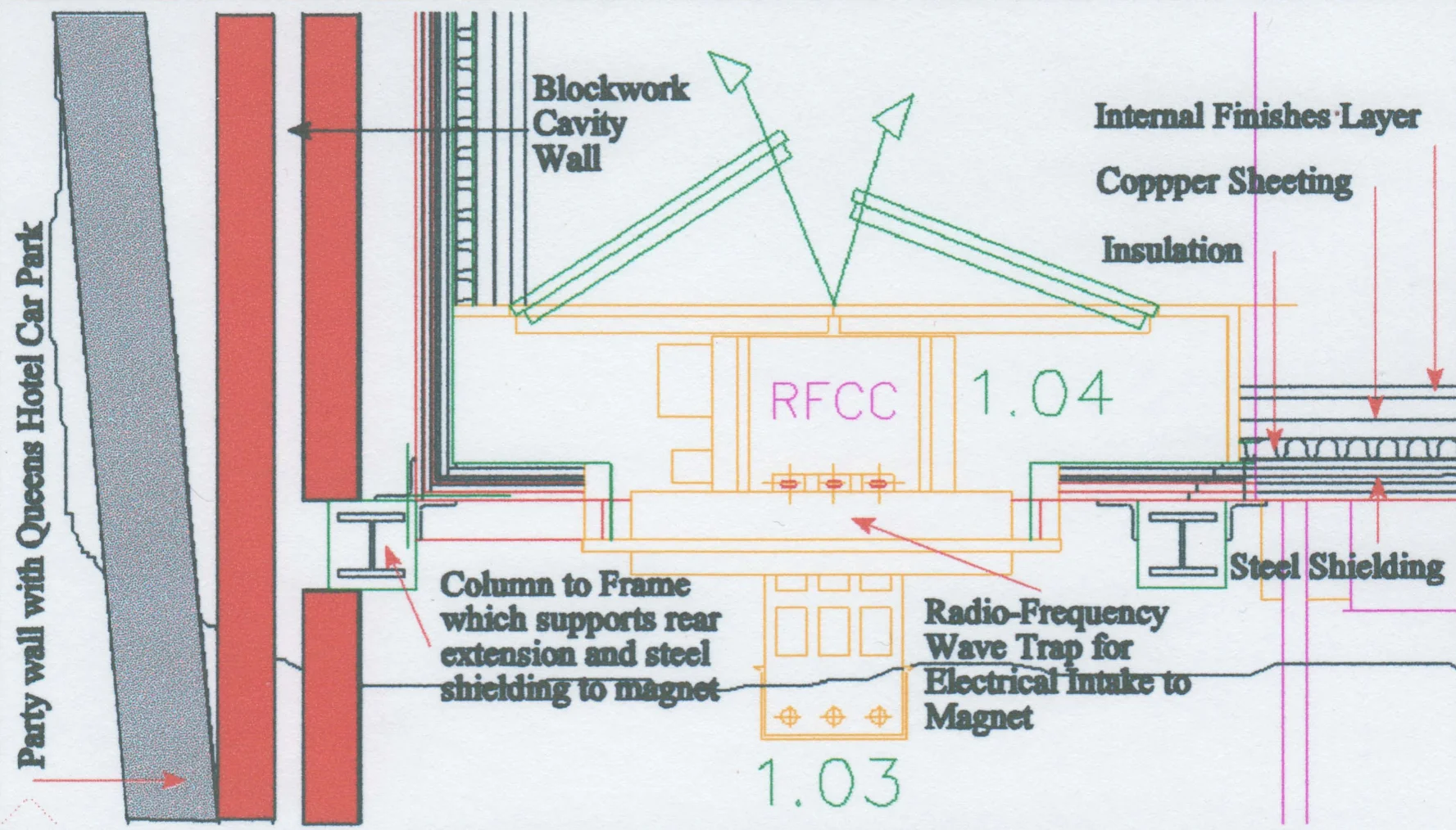
The mechanical ducting reqUirements of the room were further complicated by the recapturing of the helium vapour and transferring it to the nearby helium reliquification plant where it is re-cooled and stored for future use. This process takes place in a small room sewed by the adjacent large room to the south called the MRI Computer Room. It is in this room that the Magnefs electronic support takes place while most.

The architects knew that ultimately they could be held liable for any accident which might happen as a result of their planning of the building. They realized that the escape route traversed the magnetic field that bulged outside the open rf cabin doors when the magnet was on. Despite reassurances that the MRI power supply was cut in the event of a fire alarm and despite increasing the thick.Q.ess of the steel shielding around the magnet, they could not guarantee that a pacemaker-bearing visitor to the lab would be safe if escaping from the basement (not to mention inadvertently entering the area in normal use). Ultimately, signage prohibiting the entry of such a person to the premises of the basement would have to be displayed at all entry points. Smart card swipe security to all controlled areas of the facility were already an institution and the client signed off the general arrangement plans claiming that these issues were largely management issues.


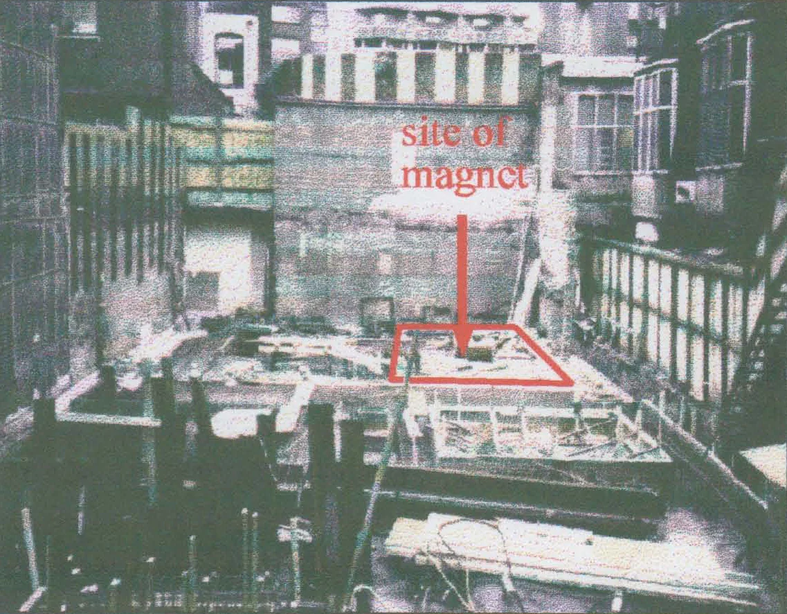

The Tender interviews for the construction subcontract of the RF Cabin and the steel shielding were limited to two invitations partly because of the specialized nature of laminating 7000 sheets of iron into a precise magnetic wave proof construction. Premise Engineering Ltd. and Genesis Medical Engineering Ltd gave wildly varying tenders for the steel shielding. One tender came in at £90,000 and the other at £30,000. Little wonder why the Project Manager gave the contract to the lesser bidder. This bearing in mind that the successful (and cheaper) tender came from a company that had recently been reformed after going into receivership. The project manager's requirement from all the subcontractors was a parent company guarantee (or a collateral warrantee) which would protect the client from sudden bankruptcy of a subcontractor. This, the successful tender company agreed to and qualified by a warrantee from irs ·parent company to commence construction of the RF Cabin.


Institutional Bank Headquarters in Triton Square, London- Schematic Design
Architecture Firm: Arup Associates
Client: British Land Plc.
Site: Triton Square, London
Date of Project: 1987- 1995
Project Summary:
Summary: JBM's role on this project in 1987 was: to provide a site analysis of the urban design issues together with the principal architect, Richard Frewer, produce a conceptual design package of drawings and models over three options, prepare a schematic design package of a single final option and present the concepts to the client, British Land.
In 1987 British Land, real estate developers of The Euston Centre approached Arup Associates architects to provide a concept for
1) Demolition of the 1950s buildings which existed in Euston Centre
and
2) Re-development of Triton Square.
Initially, Arup had expressed an interest in occupying the proposed redevelopment. John Millard had recently completed RIBA Part 1 and was employed by Arup Associates in Group Six. Millard and the Principal-in-charge of the project were the first two architects affecting the initial concept.
The project was shelved after this initial schematic proposal in 1987. The completed building, which finished in 2007 retained all of the original design components including:
* The circular floor plan inside a rectangular building envelope
* The use of separate corner core elements which served the circumference of the circular occupied space managed vertical penetrations and simplified the concrete structure by constraining the vertical penetrations in separate steel corner structures.
* The introduction of a central occulus was retained and refined in the final design.
Specific Role by John Millard: 1) Originate all Schematic drawings, 2) Part of a team of two architects, JM assisted the principal in charge of the design, 3) Coordinate Engineering Disciplines, 4) Produce all Schematic Phase Drawings for approval by Owner...Project was mothballed in 1987 and later constructed in 1997.
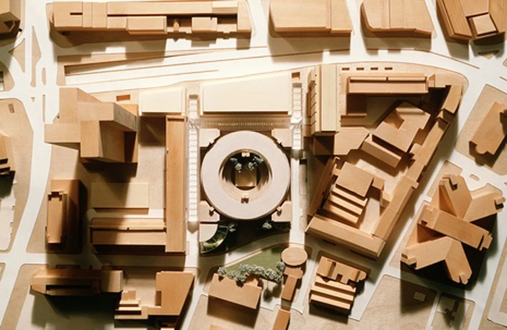
This site massing model was presented to British Land to make the case for the building design strategy. Since the existing adjoining buildings encroach upon the target site, the design strategy relies upon availability of natural light to penetrate the floor plates through the generous opening created by a circular floor plate. At the center of the circular floor plate, a large occulus through which daylight is regulated by motorized louvers and low thermal emission glass.
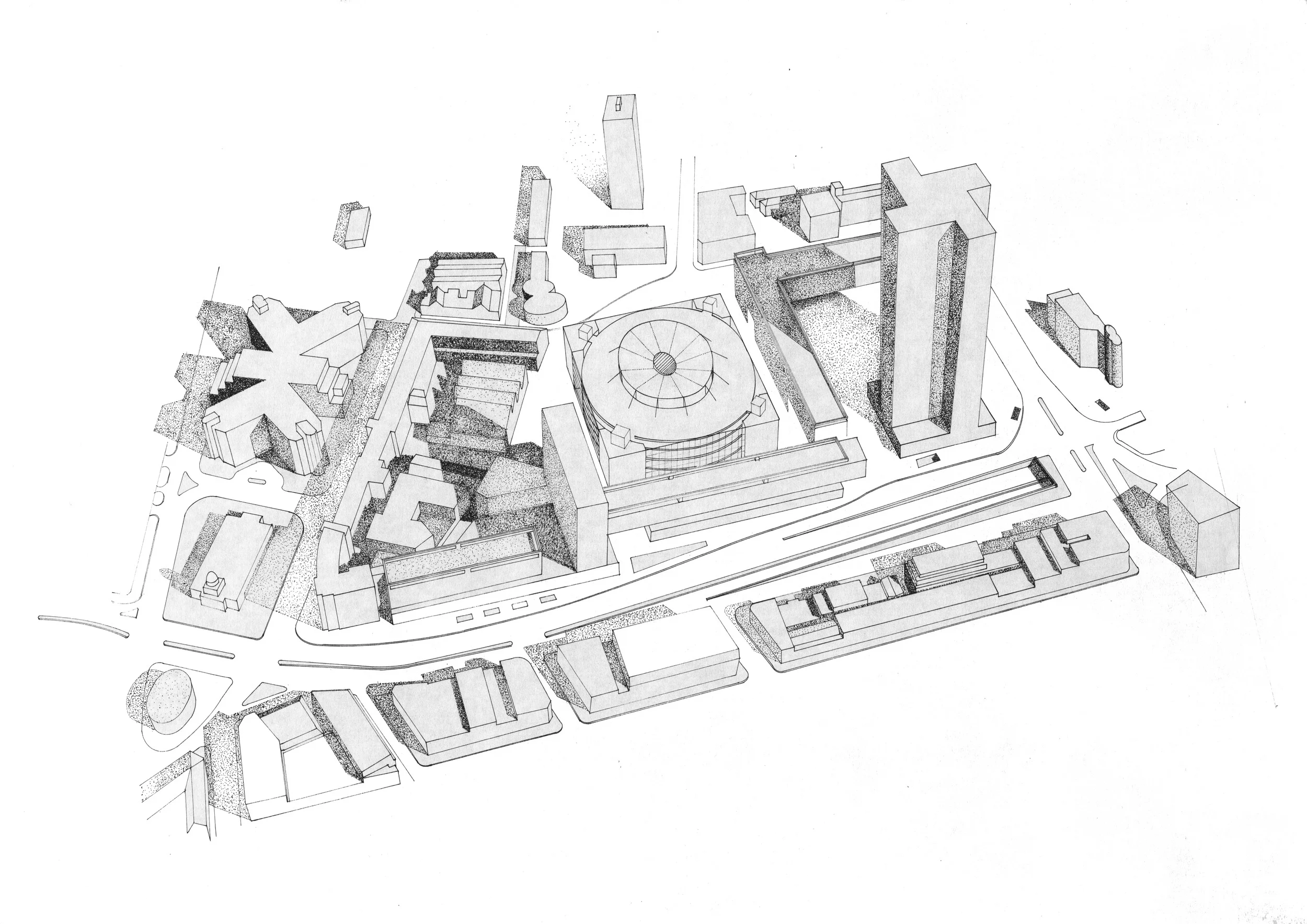
The site was pre-occupied by post-war buildings that were considered at the time to have been designed with minimal floor to floor heights that were incompatible with modern air conditioning strategy. The new proposal broke all conventions by introducing a radial structure with a round slab and corner cores.
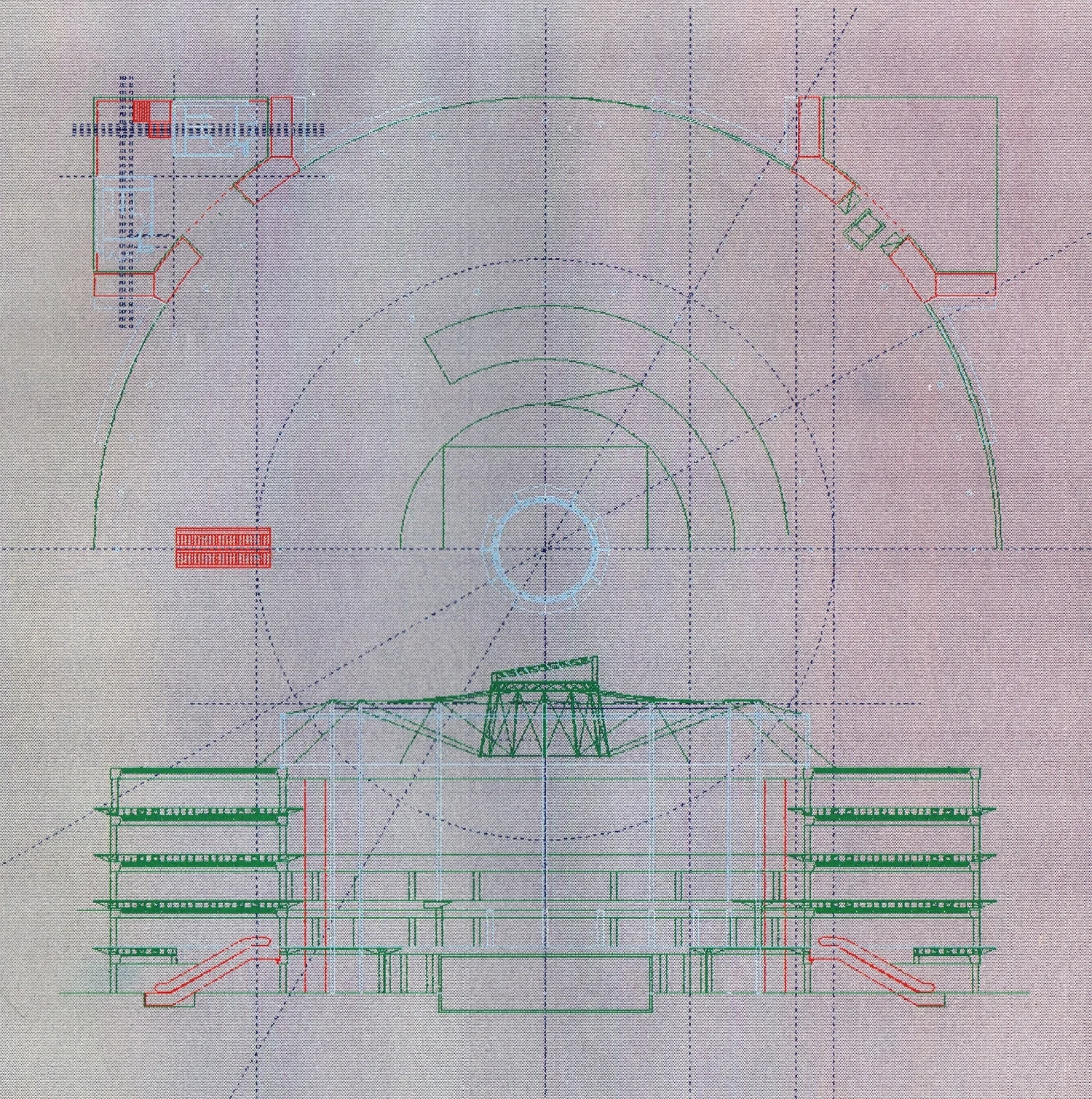
The sketch above shows conceptual level design development carried out on Arup's 1987 era computer aided design system by McDonnell Douglas Information Systems called "GDS" or Graphical Data System running on a PRIME "mini-computer" which took up an entire room. The design was explore using hand drafting initially and then transposed into CAD in 2 dimensions.

The injection of conditioned air into a floor plenum from the corner cores into the occupied space of the building allowed for the penetrations from the roof mounted air handling equipment to be located exclusively in the corners of the building where steel construction facilitated the routing of ducts to occur. The circular concrete structure was allowed to span unimpeded by mechanical penetrations.

This schematic section shows the extended floor plates that are achieved using cantilevering precast concrete units that are anchored into the slab edge around the circumference of the radial floor. This modest increase in usable area assists with the relatively in-efficient gross-to-net-area ratio of the building. The central courtyard serving as the primary offender in reducing the usable area of the building.
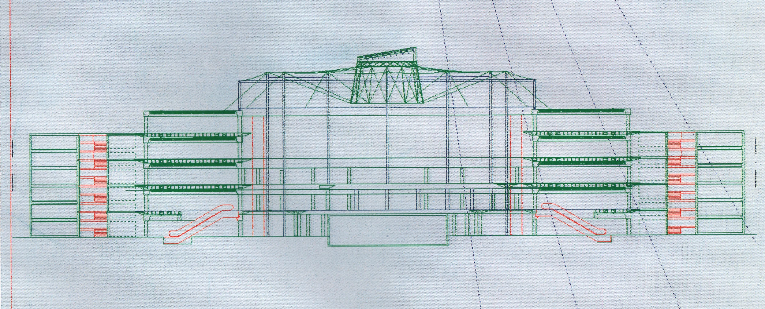

Peter Rice, a structural engineer with Arup had been involved in the design of Cité des Sciences et de l'Industrie, the largest science museum in Europe by architect, Adrien Fainsilber. Central to the design of Cité des Sciences et de l'Industrie was a pair of occuli that regulated daylight using a motorized, mirrored opening in the roof that reflected daylight into the enormous space of the museum. At Arup Associates, for the design of the Triton Square Project, I promoted the same concept which was adopted in the final design for the building.
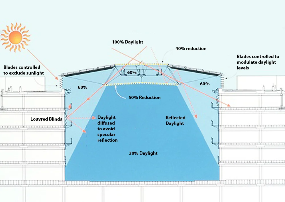
As can be seen in the section, the penetration of sunlight through the roof opening is controlled through use of translucency and reflection as well as direct sunlight. The objective: minimize solar heat gain while maximizing the amount of natural light.
Institutional Bank Headquarters in Triton Square, London- Design Development
Architecture Firm: Arup Associates
Client: British Land Plc.
Site: Triton Square, London
Date of Project: 1987- 1995
Project Summary:
Summary: JBM's role on this project in 1987 was: to provide a site analysis of the urban design issues together with the principal architect, Richard Frewer, produce a conceptual design package of drawings and models over three options, prepare a schematic design package of a single final option and present the concepts to the client, British Land.
In 1987 British Land, real estate developers of The Euston Centre approached Arup Associates architects to provide a concept for
1) Demolition of the 1950s buildings which existed in Euston Centre
and
2) Re-development of Triton Square.
Initially, Arup had expressed an interest in occupying the proposed redevelopment. John Millard had recently completed RIBA Part 1 and was employed by Arup Associates in Group Six. Millard and the Principal-in-charge of the project were the first two architects affecting the initial concept.
The project was shelved after this initial schematic proposal in 1987. The completed building, which finished in 2007 retained all of the original design components including:
* The circular floor plan inside a rectangular building envelope
* The use of separate corner core elements which served the circumference of the circular occupied space managed vertical penetrations and simplified the concrete structure by constraining the vertical penetrations in separate steel corner structures.
* The introduction of a central occulus was retained and refined in the final design.
John Millard's Role- 1) Originate all Schematic drawings, 2) Part of a team of two architects, JM assisted the principal in charge of the design, 3) Coordinate Engineering Disciplines, 4) Produce all Schematic Phase Drawings for approval by Owner...Project was mothballed in 1987 and later constructed in 1997.
Summary: JBM's role in this project was limited to a 1987 schematic phase with Principal in charge, Richard Frewer (Architect) and Charles Wymer (Structural Engineer). All design development drawings shown below were by JBM as carried out in 1987. These drawings were superseded by 2007 efforts by others at Arup Associates.
The building became occupied by the Bank of Chicago in 1998.
The building is six stories of occupied space that equate to approximately 270,000 square feet of usable space. The circular plan of the schematic design became an octagonal design in design development. Use of the building as a banking center continues to this day.
Reduction of heat gain from the sun through the occulus was a key consideration for the building climate given the excessive number of transistor loads on the trading floors from personal computers. These created a heat gain additional to the solar heat gain which when compounded together could have presented a major cooling load and extended energy costs for the building.
The occulus measures nearly forty feet in diameter. It is supported by an octagonal frame which houses a clerestory window that has motorized louvers. These prevent direct sunlight from heating the interior climate. The translucent fiber-glass liner that is stretched across the underside of the occulus support structure also reduces direct sunlight from penetrating into the space. This diffuse light from the translucent fiber-glass membrane is accompanied by reflected artificial light from below as well as diffused artificial light from above.
The first floor is served by escalators from street level at the main entrance. There is a five storey entrance hall over these escalators which are in character with the exterior cladding and glazing, bring the exterior fenestration to the interior of this grand entrance.
The delivery of cooling air from the roof mounted chillers is constrained to the corner cores which contain the risers associated with supply air. The conditioned air is then driven into a floor plenum which provides for diffusion of fresh air through the raised floor which also delivers power and data to the workstations.
The building also incorporates a trademark Arup energy feature which was pioneered in Woking and Broadgate which is an extra skin to the envelope of the building that serves as an insulating element from the extremes of temperature in the exterior environment by removing direct thermal bridges to the interior.
The external glazing incorporates a thermal flue which reduces winter heating loads and summer cooling loads. All external glazing to office areas is protected by motorised blinds linked to the building management system.


Institutional Bank Headquarters in Triton Square, London- Completed Construction Photos
Architecture Firm: Arup Associates
Client: British Land Plc.
Site: Triton Square, London
Date of Project: 1987- 1995
Project Summary:
Summary: JBM's role on this project in 1987 was: to provide a site analysis of the urban design issues together with the principal architect, Richard Frewer, produce a conceptual design package of drawings and models over three options, prepare a schematic design package of a single final option and present the concepts to the client, British Land.
In 1987 British Land, real estate developers of The Euston Centre approached Arup Associates architects to provide a concept for
1) Demolition of the 1950s buildings which existed in Euston Centre
and
2) Re-development of Triton Square.
Initially, Arup had expressed an interest in occupying the proposed redevelopment. John Millard had recently completed RIBA Part 1 and was employed by Arup Associates in Group Six. Millard and the Principal-in-charge of the project were the first two architects affecting the initial concept.
The project was shelved after this initial schematic proposal in 1987. The completed building, which finished in 2007 retained all of the original design components including:
* The circular floor plan inside a rectangular building envelope
* The use of separate corner core elements which served the circumference of the circular occupied space managed vertical penetrations and simplified the concrete structure by constraining the vertical penetrations in separate steel corner structures.
* The introduction of a central occulus was retained and refined in the final design.
John Millard's Role- 1) Originate all Schematic drawings, 2) Part of a team of two architects, JM assisted the principal in charge of the design, 3) Coordinate Engineering Disciplines, 4) Produce all Schematic Phase Drawings for approval by Owner...Project was mothballed in 1987 and later constructed in 1997.
Summary: JBM's role in this project was limited to a 1987 schematic phase with Principal in charge, Richard Frewer (Architect) and Charles Wymer (Structural Engineer). All design development drawings shown below were by JBM as carried out in 1987. These drawings were superseded by 2007 efforts by others at Arup Associates.
The building became occupied by the Bank of Chicago in 1998.
The building is six stories of occupied space that equate to approximately 270,000 square feet of usable space. The circular plan of the schematic design became an octagonal design in design development. Use of the building as a banking center continues to this day.
Reduction of heat gain from the sun through the occulus was a key consideration for the building climate given the excessive number of transistor loads on the trading floors from personal computers. These created a heat gain additional to the solar heat gain which when compounded together could have presented a major cooling load and extended energy costs for the building.
The occulus measures nearly forty feet in diameter. It is supported by an octagonal frame which houses a clerestory window that has motorized louvers. These prevent direct sunlight from heating the interior climate. The translucent fiber-glass liner that is stretched across the underside of the occulus support structure also reduces direct sunlight from penetrating into the space. This diffuse light from the translucent fiber-glass membrane is accompanied by reflected artificial light from below as well as diffused artificial light from above.
The first floor is served by escalators from street level at the main entrance. There is a five storey entrance hall over these escalators which are in character with the exterior cladding and glazing, bring the exterior fenestration to the interior of this grand entrance.
The delivery of cooling air from the roof mounted chillers is constrained to the corner cores which contain the risers associated with supply air. The conditioned air is then driven into a floor plenum which provides for diffusion of fresh air through the raised floor which also delivers power and data to the workstations.
The building also incorporates a trademark Arup energy feature which was pioneered in Woking and Broadgate which is an extra skin to the envelope of the building that serves as an insulating element from the extremes of temperature in the exterior environment by removing direct thermal bridges to the interior.
The external glazing incorporates a thermal flue which reduces winter heating loads and summer cooling loads. All external glazing to office areas is protected by motorised blinds linked to the building management system.


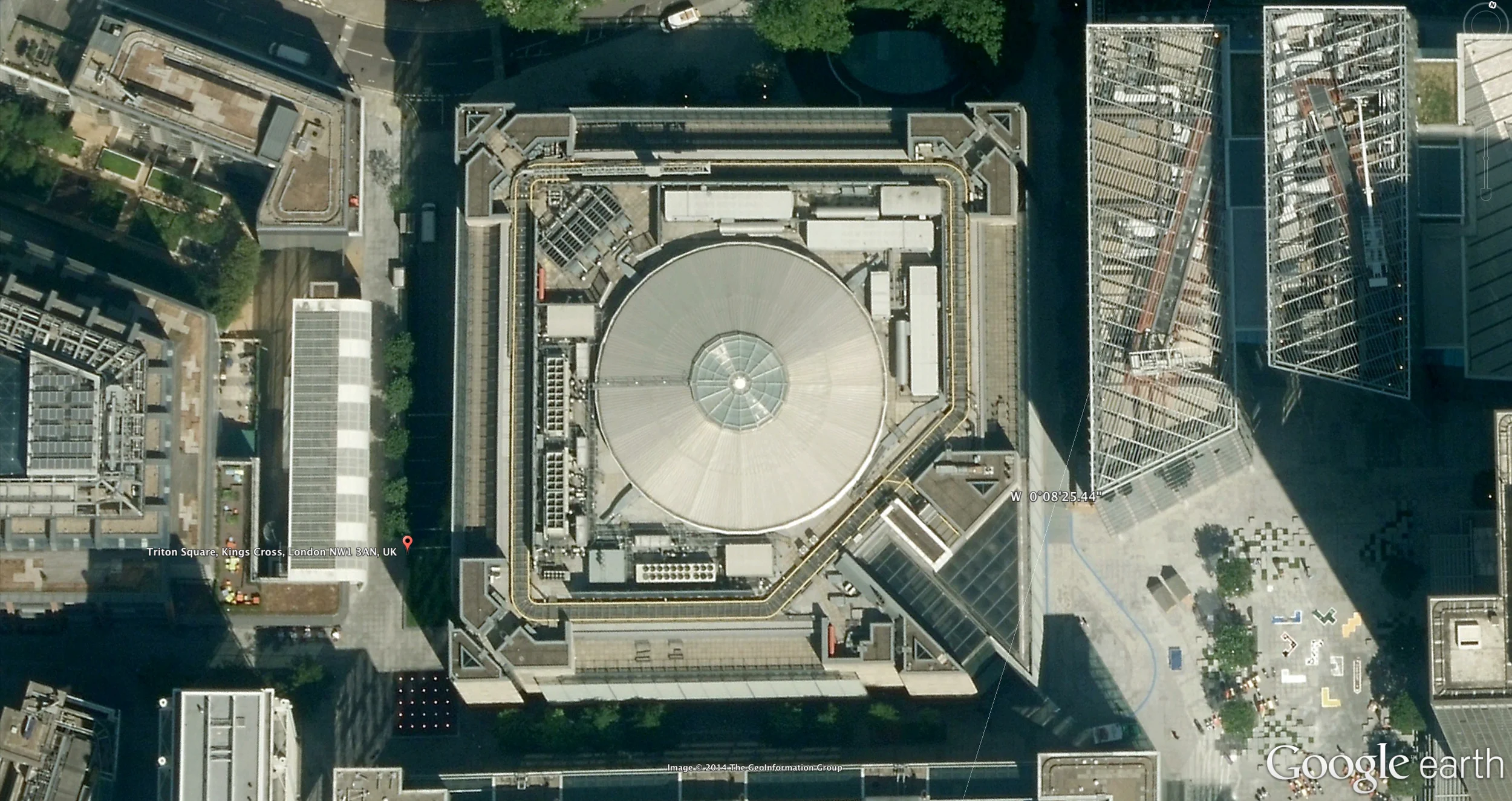

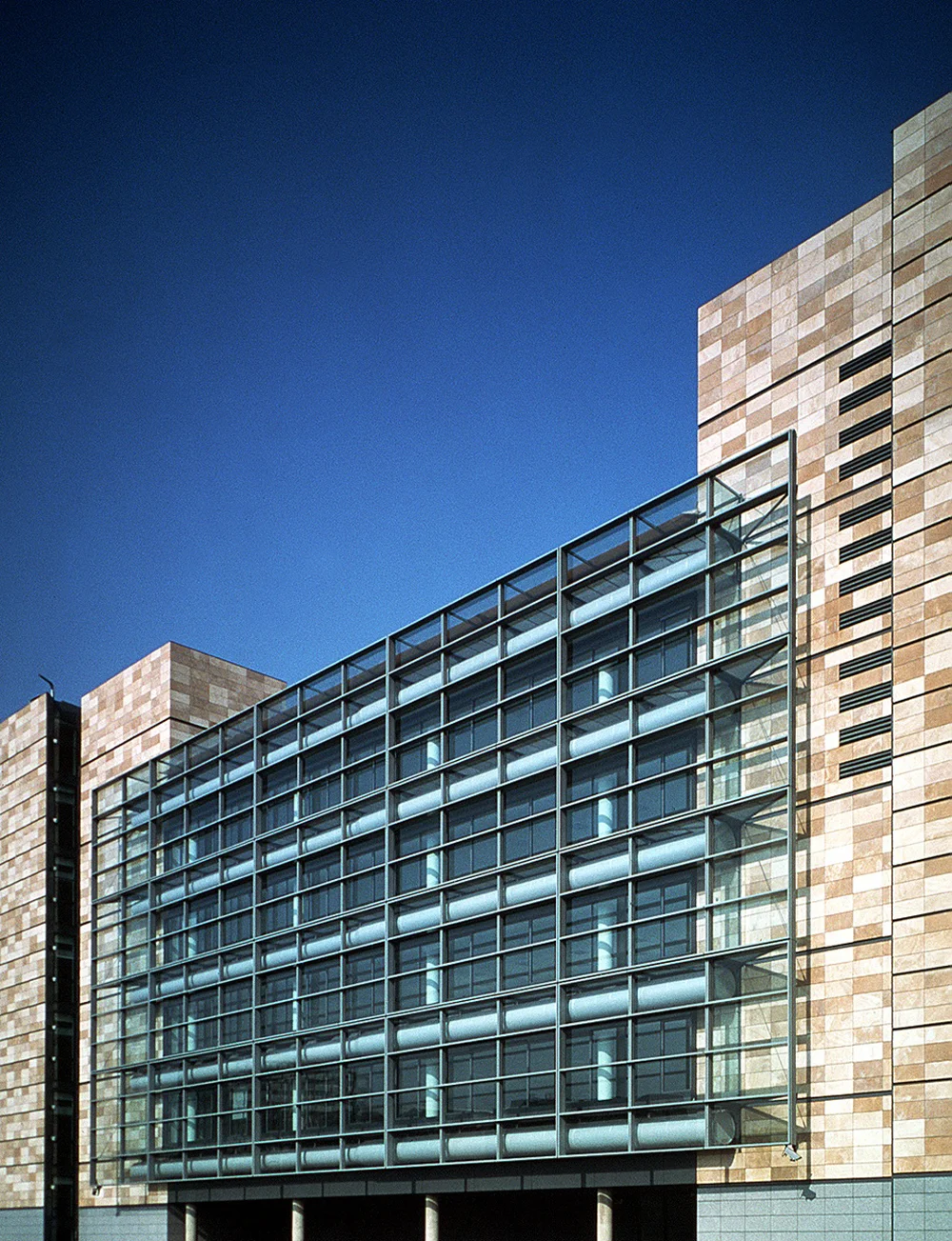


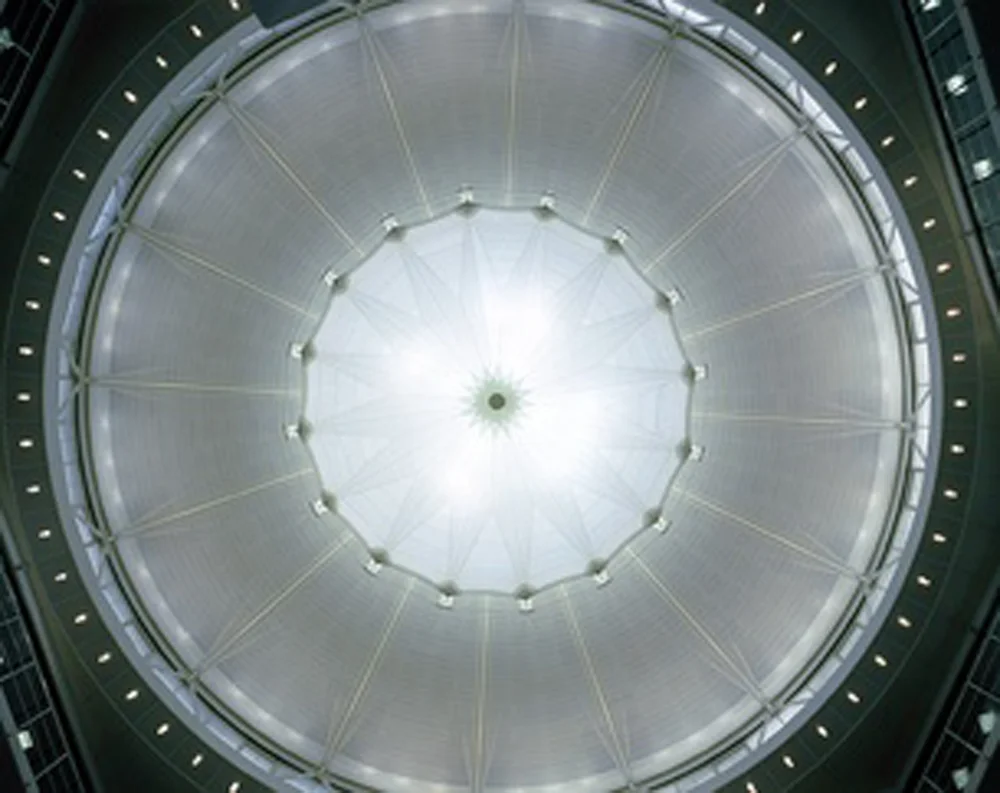
Restoration of British Rail- Crystal Palace Low Level Station
Architecture Firm: John Millard t/a Helix Studio
Client: British Rail/ Roseberry's Fine Art
Site: Crystal Palace Low Level Station, Sydenham, London
Date of Project: 1990- 1991
Project Summary: This study, sponsored by Roseberry Fine Art- tenant of the Crystal Palace Low Level Station Booking Hall resulted in the renovation of this historic Joseph Paxton designed station owned by British Rail and subject to English Heritage Listed Building Status as a Grade 2 listed building. In addition to the renovation of the existing station, a development project by John Millard proposing a 130,000 sf rail and road vehicle museum and professional offices and corporate accommodation accompanied the restoration project.
John Millard's Role- I executed two contracts with the client- one contract for Historic Buildings, Repairs and Conservation Work and one contract for A Development of the Low Level Station owned by British Rail. These contracts were executed after a significant amount of investigation into the project together with my previous employers at Arup Associates and an extensive amount of work carried out for my Diploma Portfolio at The Architectural Association School of Architecture. I carried out a measured survey of the entire Low Level Station and produced measured drawings by hand. I employed one other architect to carry out these drawings. His name is Elden Croy, AA Dipl. RIBA.
Table of Contents;
1. 1871 Ordnance Survey Map
2. History of the Low Level Station
3. Isometric of the Low Level Station (DRWG. S110A)
4. Exploded Isometric (DRWG. S110B)
5. Isometric Section taken at Vault Level (DRWG. Sl10C)
6. Contemporary Transport Services
7. Transport Services Plan (DRWG. S100)
8. The Crystal Palace Park Grounds and Occupants
9. Crystal Palace Park Plan (DRWG. S101)
10. Recommendations for Development of the L.L.S.
11. Existing Plan of Southwestern Park Edge. (DRWG. S102)
12. Existing Pedestrian and Vehicular Access Plan (DRWG.
13. Access Proposals 1 & 2
14. Plan of Proposal 1 (DRWG. S210A)
15. Plan of Proposal 2 (DRWG. S211A)
16. Conclusion of Access Report
17. Plan of Proposal 3 (DRWG. S212A)
History of the Low Level Rail Station;
An Act of Parliament authorized the Crystal Palace branch line on 8th July, 1853 shortly after work began on reconstruction of the Crystal Palace on Sydenham Hill, 5 August, 1852. Originally the Station was designed as a terminus, but another Act of 4th August 1853 enabled the West End of London & Crystal Palace Railway to extend a line from Wandsworth to five intermediary destinations and finally nthrough a 745 foot long tunnel to the west wall of the Low Level Station. West-bound trains began arriving at the final destination of the Thames at Battersea Wharf on 29th March, 1858. The building itself was designed in three sections by Frederick Dale Banister and Whitney Mannering. These sections comprised;
1) Booking Hall & General Waiting Room 69ft. X 35ft. covered by a semicircular cast-iron vault with a clerestory 12ft. wide and 4ft. high along the crest. The floor was paved i~ Minton Tiles and incorporated into a concrete raft which was supported by cast iron girders and jack arches of nine inch brickwork.
2) A 2-storey tower immediately to the north containing two corridors each 41ft. X 11ft. 1st and 2nd class Ladies waiting rooms and lavatories each 23ft. X 15ft. and lSft.X 17ft. respectively. On the ground floor, a large dining room was provided with a refreshment bar and a cloakroom 20ft. X 15ft. On the first floor, a second dining room was provided together with kitchens and associated rooms. The roof was a very high pitched mansard roof covered in zinc and topped by a decorative wrought iron balustrade round the crowning square.
3) A 2-storey tower immediately to the south containing a booking office, a telegraph office and waiting rooms with first, second and third class waiting rooms and lavatories. Stationmaster's accommodation on the first floor comprised a living room, four bedrooms and a kitchen plus lavatory. The road bridge which spanned between Anerly Hill and the Palace Grounds was widened by 10ft. to accommodate a porte cochere of five cast-iron glazed bays. History of the Low Level Station (continued) ... The Low Level Station offered four tracks which were served by three double faced island platforms. The central platform served the two roads which proceeded through to West Norwood. The outer two tracks terminated at the Low Level Station where 10,000 passengers were delivered each weekday. The platforms were contained by two 456ft. long retaining walls with a third spinewall running down the centre of the station, dividing the central platform and supporting two cast-iron glazed vaults which sheltered the entire length of the platforms. The breadth of this space was 115ft. totaling some 52,000sq.ft. of area and terminating with a tall space covered by a series of 3 warren truss sheds with clerestories at each ridge. This space contained 4 brick stairs rising 22ft. to the booking hall. Below the stairs, there existed accommodation for railworkers. At the opposite end of the platforms, a turntable was placed central to the through tracks. Drawings which illustrate the present day Low Level Station can be found on pages 4, 5 & 6 of this report. On page 4, a three dimensional drawing shows the station and its immediate environs including the station approach road and neighboring Ledrington Road. The small chapel which exists from Victorian times is indicated by a number 9 on the legend and on the chapel itself on the drawing. In this way the other features of the building which still exist can be located in the legend with the exception of the Mansard Roof over the South Tower which no longer exists but has been drawn here to show a proposed restoration of that element. On page 5, the three dimensional drawing has projected certain elements of the building into space in order that the breakdown of the building's interior can be better understood.On page 6, only the sub-structure of the station can be understood. The purpose of this drawing is to assist with any conversation regarding use of these spaces for access or accommodation in the future.
Contemporary Transport Services to the Low Level Station;
The Site of the Low Level Station is indicated at the centre of Drawing S100 on page 8. The Low Level Station remains in use by British Rail. Of the four lines which served the Low Level Station, one line shall remain in use. Additionally the modern day station offers a service on the two Norwood lines. These lines offer mainline Victoria to Norwood Junction/ Beckenham Junction services operating eight passenger trains per hour increasing to eleven during peak hours. There is a main line service to London Bridge with connections at New Cross Gate for Docklands. The Thameslink service also offers connections from Crystal Palace with Blackfriars, St.Paul's, Farringdon, King's Cross and The North as well as southern destinations including West Croydon, Epsom and Guildford.
The Crystal Palace Park Grounds and Occupants;
The National Sports Center, administered by The Sports Council, is a primary tenant of the Crystal Palace Grounds. The grounds occupied by The Sports Council are indicated by a red line surrounding the sports facilities due north of the Low Level Station Site in drawing S101 on page 10. This lease line encompasses the access requirements of the sports facilities but does not include adequate parking for the day to day requirements of the administrative personnel at the Jubilee Stand nor for the needs of mass spectator events in the sports arena. The Sports Council lease expires in the year 2004 and is currently being renegotiated with Bromley, the owners of the palace grounds.
Another occupant of the site includes a caravan site which has recently moved from a site in the park set aside by Bromley Council for future development. The caravan park has consolidated its position in a landscaped remote area indicated by a red leaseline on drawing S101 in the north-western corner of the park.
The site set aside for future development is indicated on DRWG. S101 as a Hotel Site. This is located in the western extreme of The Park. Holiday Inn is about to become guarantor of a major leisure development including a 150 bedroom hotel, a four screen cinema complex, a health club, indoor and outdoor tennis courts plus a 600 car parking facility.
The primary occupant of The Park is the owner of the park, Bromley Council. Bromley's major interest in the park is that The Crystal Palace Park be retained by the comunity for leisure use. Any development of this land must therefor conform to the Parliamentary Act which protects the park from purely commercial use. The numerous attractions provided by Bromley include a concert bowl, landscape gardens playing fields, a cafe, archaeological exhibits, a children's playground, a museum and a zoo.
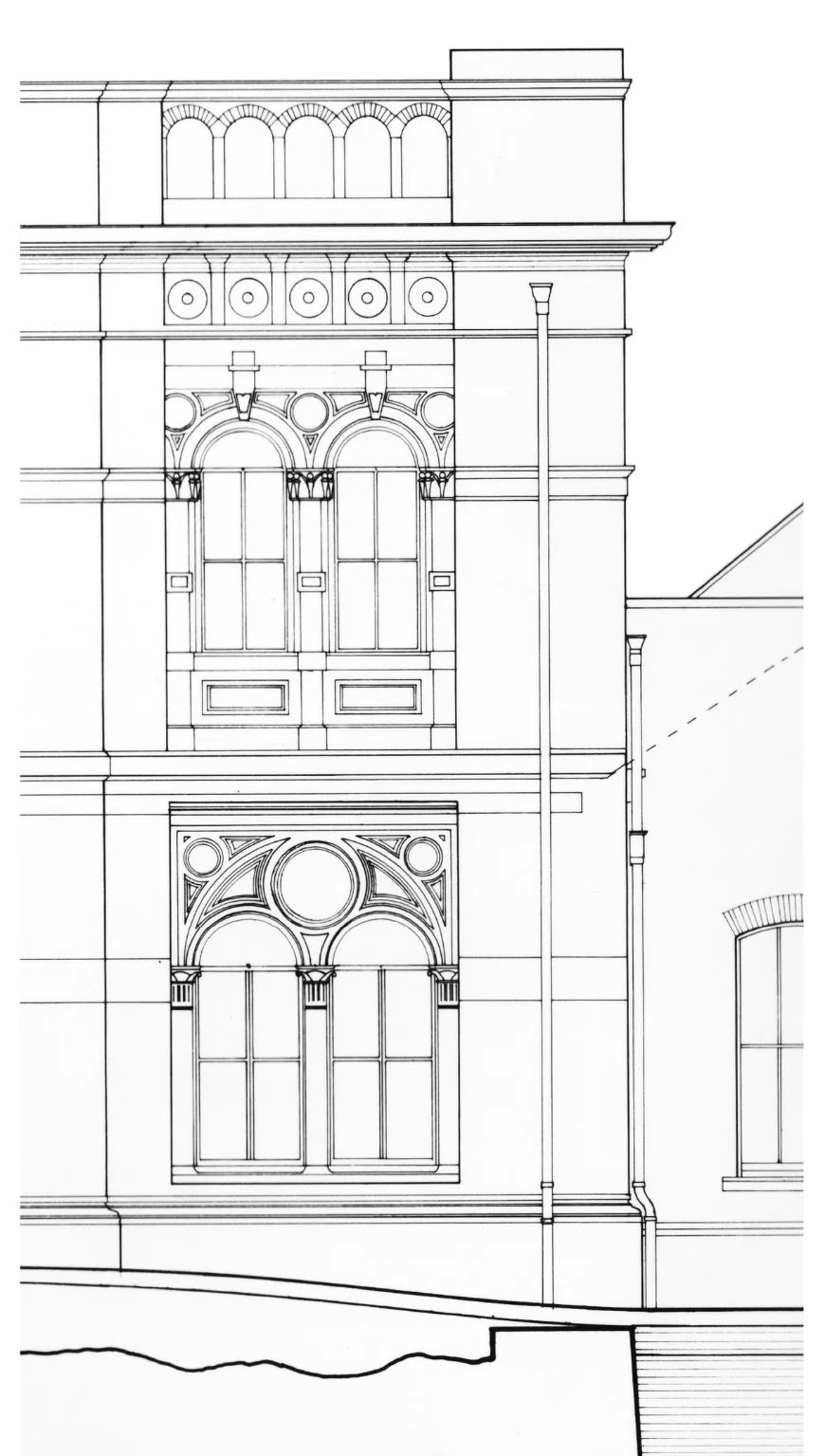
- these windows date back to 1875 (Drawing by John Millard)

-shows what remained of the station absent the Mansard Roof over the North Tower and the Porte Cochere in front of the Ticketing Office. (Drawing by John Millard)
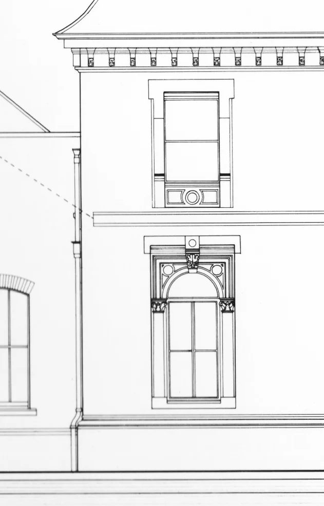
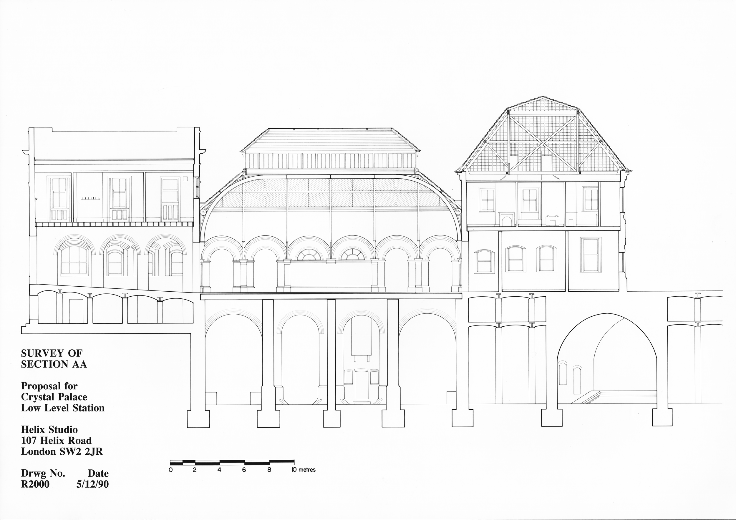
-shows extent of brick vaults that form the bridge under which rail traffic passes from the tunnel under Sydenham Hill to Bromely. (Drawing by Elden Croy)
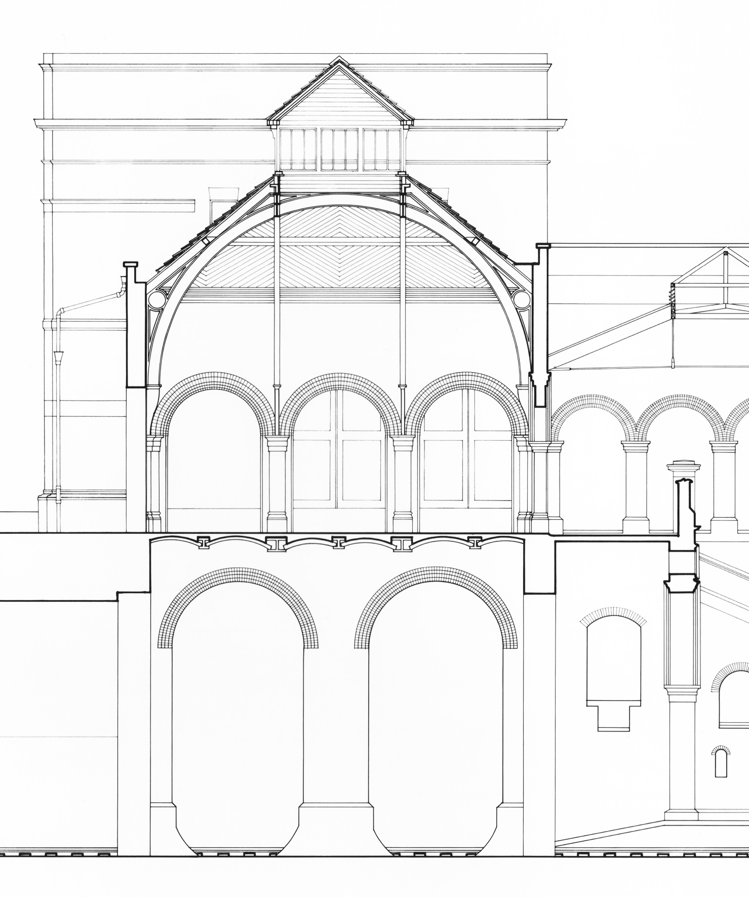
shows brick "jack arches" that support elevated ticketing level/ mezzanine to stairs leading down to platforms. (Drawing by John Millard)
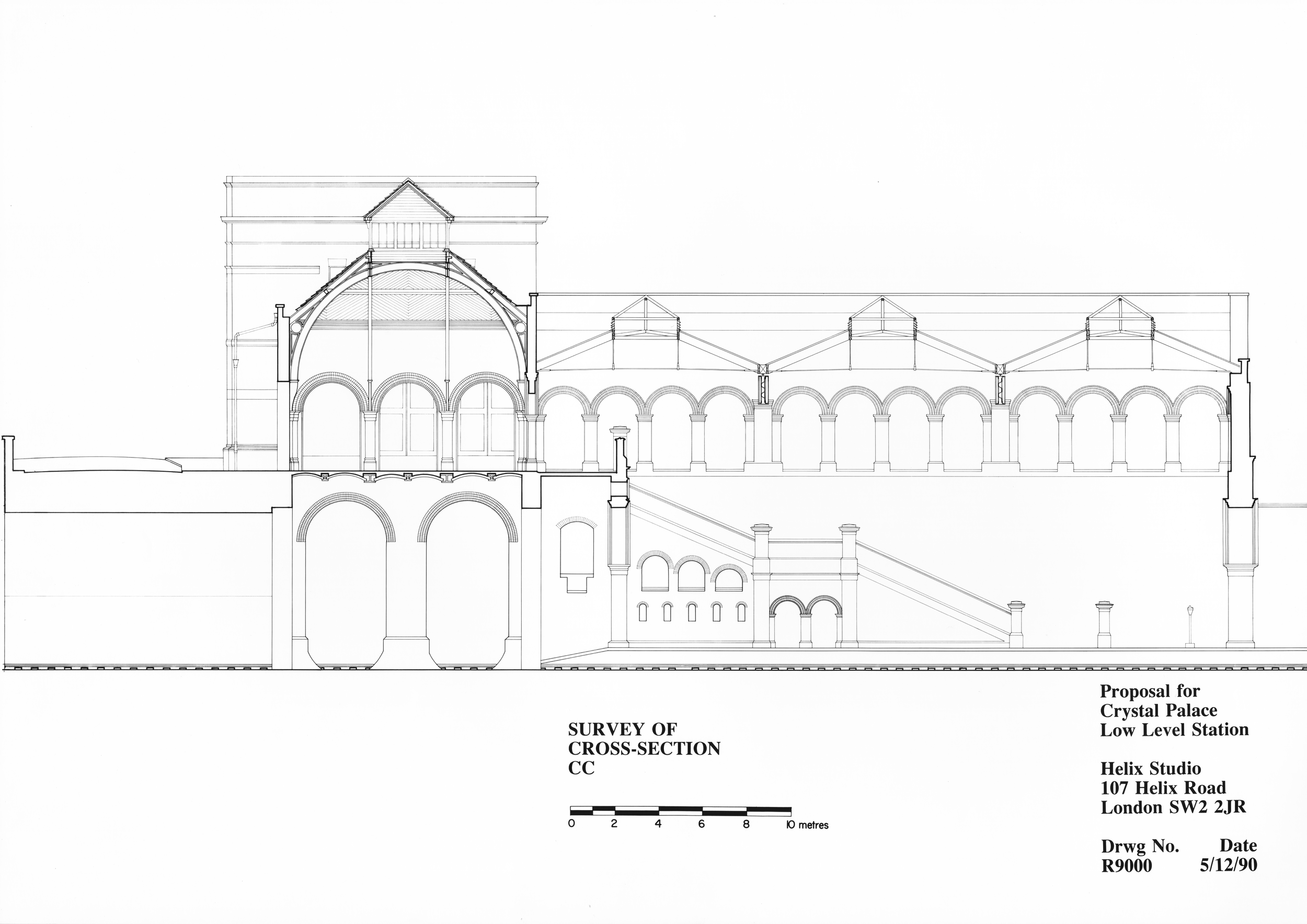
-section shows Train Shed Roof Structure that has now been restored (Drawing by John Millard)
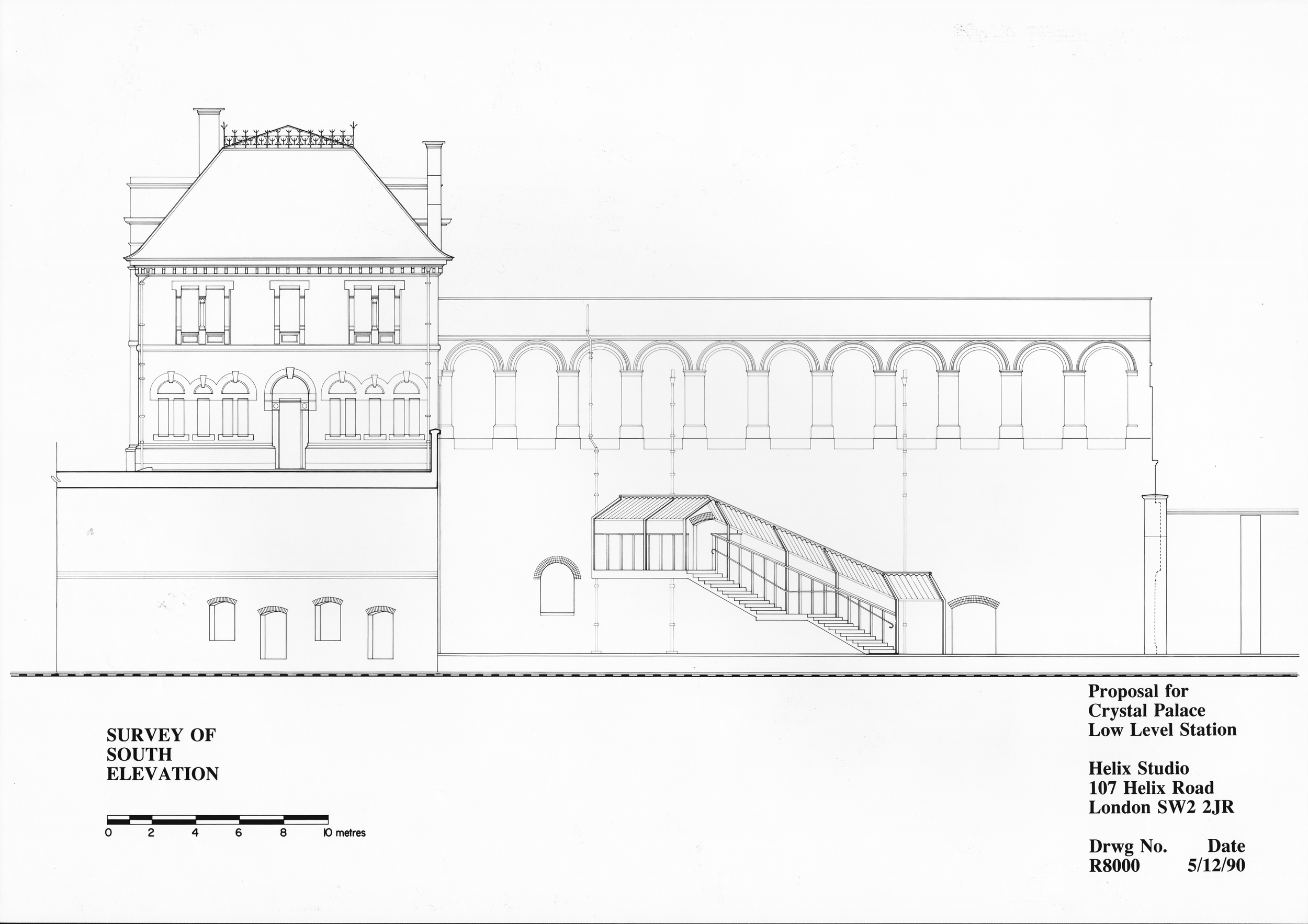
...showing stairs from train shed leading to the Bromely Spur (Drawing by Elden Croy)
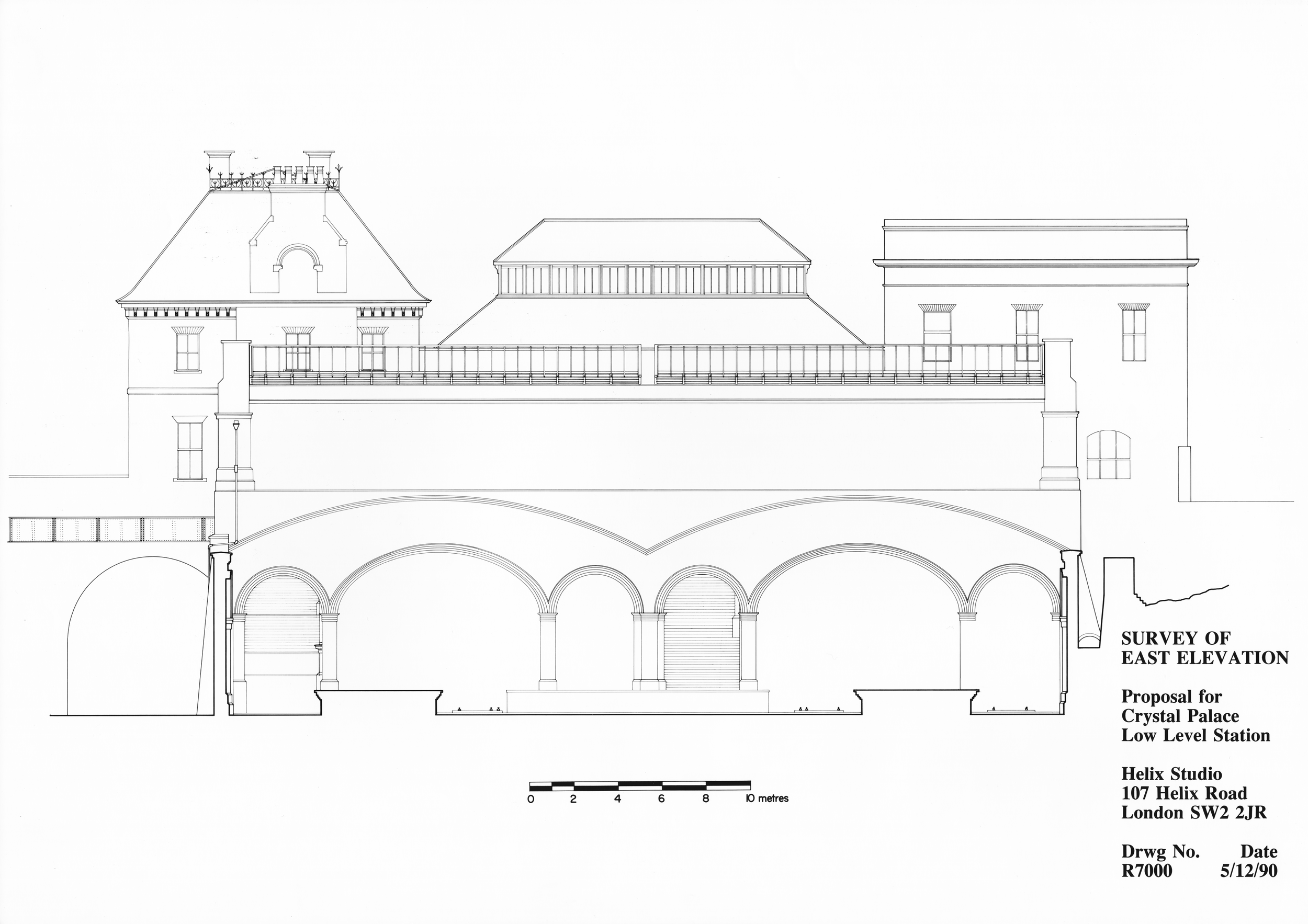
-drawing shows curved trace lines where platform canopies covered the trains for loading and unloading (Drawing by John Millard)

Drawing shows exact fenestration of wall that would define part of rail museum. (Drawing by John Millard)

- system of arches, walls and retaining walls that form the plinth of the bridge structure and brick stair cases (Drawing by Elden Croy)
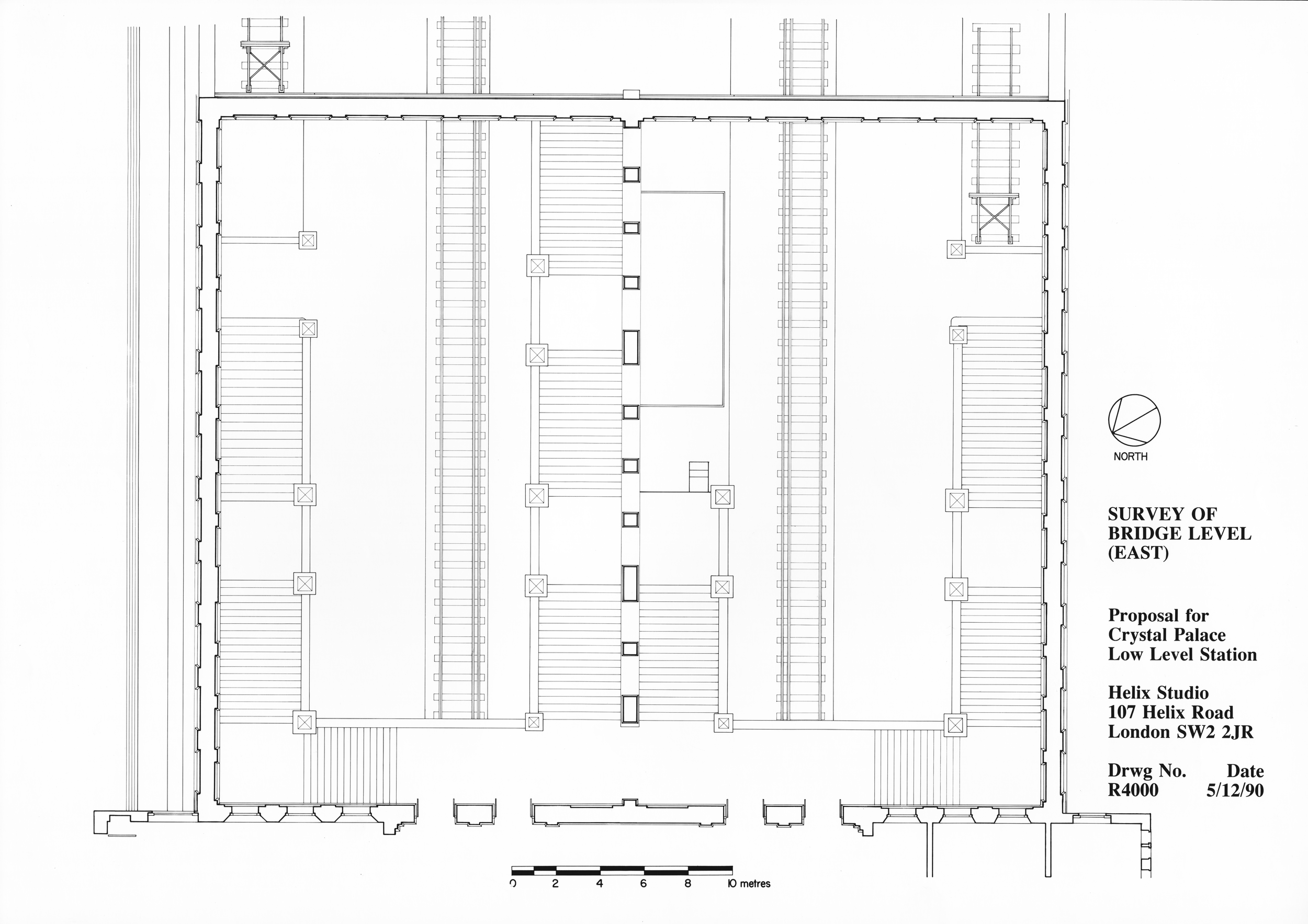
- this space is over-sailed by iron trusses that support the shed roofs and drainage systems that carry water from the roofs to scuppers in the parapet. (Drawing by John Millard)

- shows exterior grade at retaining wall outside train shed in Crystal Palace Park (Drawing by Elden Croy)

Measured Survey Drawing of North Tower (left) and South Tower (right) bridge level plans with Ticketing Hall (center) and bridge approach to the station (Train Shed omitted from plan) shows the only heated space in the entire station. (Drawing by John Millard)
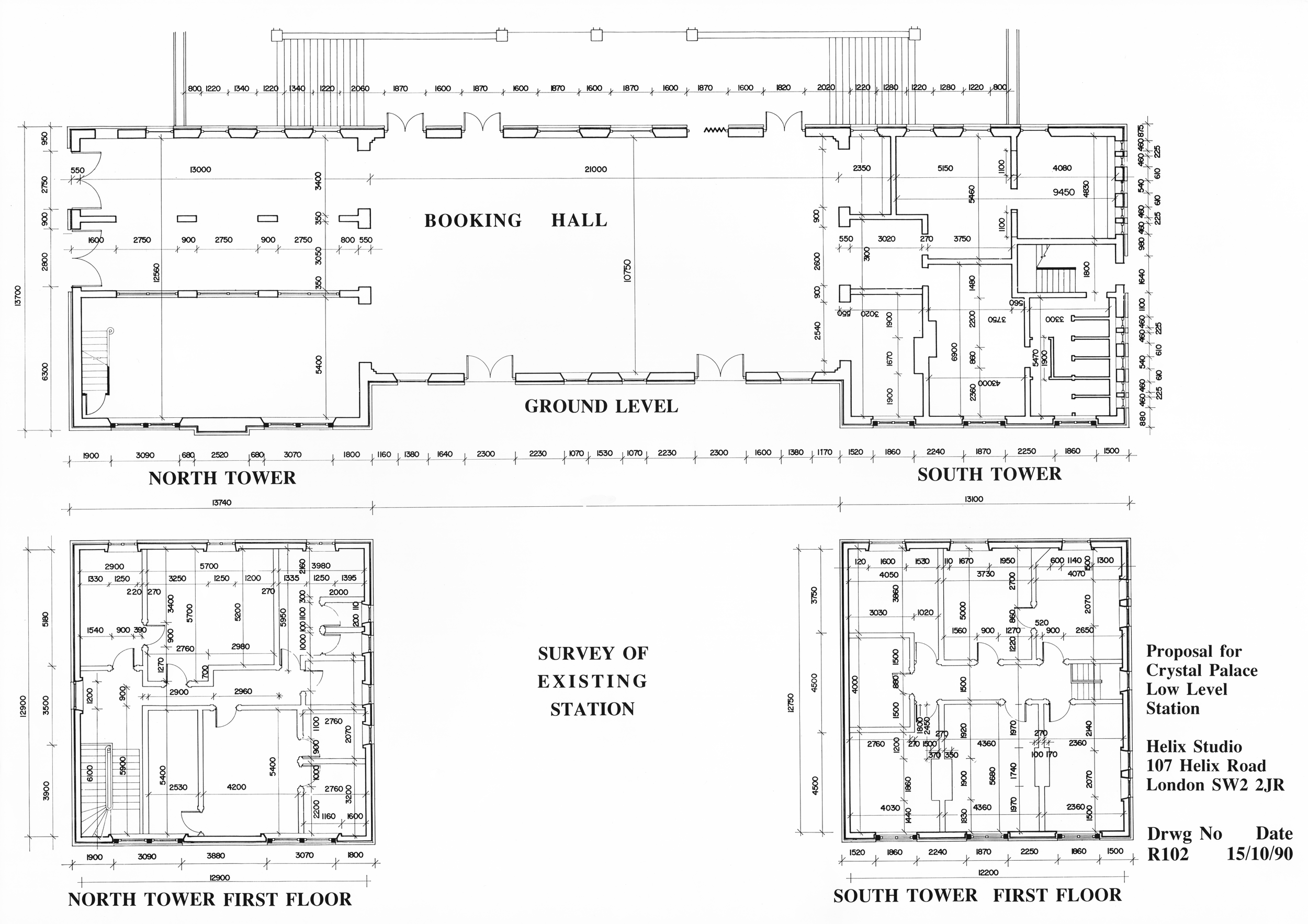
These drawings were used by British Rail to procure labor from renovation contractors who restored the building after years of dereliction. (Drawing by John Millard)

Development of British Rail- Crystal Palace Low Level Station
Architecture Firm: John Millard t/a Helix Studio
Client: British Rail/ Roseberry's Fine Art
Site: Crystal Palace Low Level Station, Sydenham, London
Date of Project: 1990- 1991
Project Summary: This study, sponsored by Roseberry Fine Art- tenant of the Crystal Palace Low Level Station Booking Hall resulted in the renovation of this historic Joseph Paxton designed station owned by British Rail and subject to English Heritage Listed Building Status as a Grade 2 listed building. In addition to the renovation of the existing station, a development project by John Millard proposing a 130,000 sf rail and road vehicle museum and professional offices and corporate accommodation accompanied the restoration project.
John Millard's Role- I executed two contracts with the client- one contract for Historic Buildings, Repairs and Conservation Work and one contract for A Development of the Low Level Station owned by British Rail. These contracts were executed after a significant amount of investigation into the project together with my previous employers at Arup Associates and an extensive amount of work carried out for my Diploma Portfolio at The Architectural Association School of Architecture. I carried out a measured survey of the entire Low Level Station and produced measured drawings by hand. I employed one other architect to carry out these drawings. His name is Elden Croy, AA Dipl. RIBA.
Contemporary Transport Services to the Low Level Station;
The Site of the Low Level Station is indicated at the centre of Drawing S100 on page 8. The Low Level Station remains in use by British Rail. Of the four lines which served the Low Level Station, one line shall remain in use. Additionally the modern day station offers a service on the two Norwood lines. These lines offer mainline Victoria to Norwood Junction/ Beckenham Junction services operating eight passenger trains per hour increasing to eleven during peak hours. There is a main line service to London Bridge with connections at New Cross Gate for Docklands. The Thameslink service also offers connections from Crystal Palace with Blackfriars, St.Paul's, Farringdon, King's Cross and The North as well as southern destinations including West Croydon, Epsom and Guildford.
The Crystal Palace Park Grounds and Occupants;
The National Sports Center, administered by The Sports Council, is a primary tenant of the Crystal Palace Grounds. The grounds occupied by The Sports Council are indicated by a red line surrounding the sports facilities due north of the Low Level Station Site in drawing S101 on page 10. This lease line encompasses the access requirements of the sports facilities but does not include adequate parking for the day to day requirements of the administrative personnel at the Jubilee Stand nor for the needs of mass spectator events in the sports arena. The Sports Council lease expires in the year 2004 and is currently being renegotiated with Bromley, the owners of the palace grounds.
Another occupant of the site includes a caravan site which has recently moved from a site in the park set aside by Bromley Council for future development. The caravan park has consolidated its position in a landscaped remote area indicated by a red leaseline on drawing S101 in the north-western corner of the park.
The site set aside for future development is indicated on DRWG. S101 as a Hotel Site. This is located in the western extreme of The Park. Holiday Inn is about to become guarantor of a major leisure development including a 150 bedroom hotel, a four screen cinema complex, a health club, indoor and outdoor tennis courts plus a 600 car parking facility.
The primary occupant of The Park is the owner of the park, Bromley Council. Bromley's major interest in the park is that The Crystal Palace Park be retained by the comunity for leisure use. Any development of this land must therefor conform to the Parliamentary Act which protects the park from purely commercial use. The numerous attractions provided by Bromley include a concert bowl, landscape gardens playing fields, a cafe, archaeological exhibits, a children's playground, a museum and a zoo.
Recommendations for the Development of the Low Level Station;
Development of the Low Level Station will require use of Bromley Council access, then for pedestrian access event of fire. Use of Council land will undoubtedly effect the day to Land. If not for automobile and means of escape in the for construction access day running of The Crystal Palace Zoo Aviary and the stables as well as the grazing area for the livestock. Much used pedestrian pathways will be interrupted or revised. Service roads for the Sports Council must be maintained and the general flow of park users from the British Rail service protected. The implications of any kind of major works to the Low Level Station in the form of a development of the two acre site between the retaining walls can more easily be understood in drawing nos. S102 & S103 of the existing site on pages 12 & 13 • The vehicular and the pedestrian pathways are indicated by orange and yellow graphics respectively. The recently completed housing development located immediately to the south of the site is indicated in brown graphics. The Zoo can be found on drawing number S102 as the buildings are actually drawn and labeled on the plan but have been omitted from the S103 plan with only a label indicating the location of the zoo for reasons of clarity and implied revision to co-exist with any proposed development.
The Leaseline of The Sports Council is indicated on the 1:2000 plan as a red line labeled in the lower section of the right margin. This line runs along the service road until the intersection of the road junction near the park entrance. From there, the leaseline follows the visitors parking access road until it reaches the athlete's accommodation and so on to circumvent the sports facilities. This leaseline portends impingement upon Sports Council land with any use of the park entrance for automobile access.
The recently completed housing development shown in brown on DRWG. S103 of the existing site will restrict access to the site to any direction except from the south. Privacy issues which portend a height restriction for the building of any development of the Low Level Station must be addressed. The houses themselves may not be overlooked by a development and will require a three hour fire rating of the building's materials to protect them from the spread of fire. The brick flanking walls may do well to provide this protection up to a height of 9 meters, beyond this the fire code will effect the construction. Feasibility of use of semi-public spaces within the housing development for means of fire escape through the flanking wall is an avenue which must be explored.
There are a number of technical obstacles which present themselves to any intended use of the building's undercroft. British Rail demolished one of the spinewall staircases to install a high voltage electrical substation indicated in DRWG. S103. This demolished stair represents an alternative approach to the north tunnel from the vaults to the train shed. Trains which have traveled through these passages since the 1850s have placed some of the brickwork structures of the building in question. Vibration has· had the effect of breaking the bond in the brickwork, especially in the chimney stacks in the upper sections of the structure, some of which have been demolished for fear of collapse onto pedestrians.
Access Feasibility Report
Proposal 1) A schematic proposal for a car park which uses The Sports Council Service Road for access to a car park for 110 cars (3/4 the requirement) can be found on the DRWG. S210A of Proposal 1 on page 15 of this report. The advantages of this proposal are limited and will require concessions from both The Sports Council and Bromley Council Chief Estate Valuer. The advantages are the following; a) minimal expense paid toward the revision of the existing road network also minimal expense due to the retention of the concrete and steel pedestrian bridge which carries pedestrians from the station to the pedestrian pathway leading to the sports arena b) immediate location of the car park next to the northern boundary of the development site offers easy pedestrian access to entranceways The disadvantages; a) substantial payment for the lease/purchase of 1.2 acres of Bromley land b) potential transgression of the Parliamentary Act which forbids commercial development of The Crystal Palace Park c) removal of livestock grazing area presently used by the Crystal Palace Zoo d) substantial payment to the Sports Council for shared use of service road unless some mutual agreement can be found
Proposal 2) A schematic proposal for a car park which also provides for most of the parking requirement but conceivably avoids many of the disadvantages of Proposal 1 also minimizes the environmental impact of the car park. This proposal could satisfy the parking requirement but in doing so could become cost prohibitive and maintainence intensive. The advantages; a) Use of any Bromley Council Land avoided ••• b) Use of any Sports Council Lease Land avoided ••• c) Multi-layer car park minimizes foot print area of car park d) Existing forestation around proposed site of car park visually camouflages the structure •••• car tion e) Location is close to entrance of development. f) Structure and organization of the interior of the park could act to separate the visitors to each destinawithin the development •••• g) Car park would not be effected by sound of passing trains below ..•• The disadvantages; a) Cost of construction exorbitant compared to surface parking with landscaping ••. b) Maintenance and Security could prove costly •.•
Proposal 3) A schematic proposal for a car park which could prove to be economical and satisfactory to both Bromley Council and The Sports Council may lie in relocating a disused 300 car park which presently exists on the site. This proposal recommends relocation of the disused car park from its present location near the central stair to a new location nearer the Low Level Station and the sports arena. This new location will offer shared use of the car park by visitors to the Low Level Station during weekdays and visitors to the Sports Arena on the weekends and evenings. The residual space created near the central stair would serve to provide the park with a new landscaped area where there was once a 300 car park. Other advantages include; a) Relocation of the car park would provide the opportunity to revise the presently confusing road layout at the Park entrance. b) The proposed location of the new car park would lend itself to escavation and pose no threat to existing landscaping (as opposed to the extensive landscaping which would be demolished by Proposal 1.) c) The grazing area for Crystal Palace Zoo livestock could be incorporated into the pedestrian approach to the Low Level Station development in some fashion which would enhance the exposure of the proposed museums to pedestrian traffic. d) Visitors to the Sports Arena would be located closer to the turnstiles entrance and in a more strategic position for stewards and minders who may be supervising the event. e) Departing sports event traffic could be divided into two queues. One queue to a Rockhills Exit and one to the existing main park exit. Overflow parking could be provided on the Overflow Parking Lawn indicated in DRWG. S212A plan of proposal 3. The disadvantages; a) Pedestrians would have to walk an additional 20 meters to the development reception. b) The developer may have to finance the additional landscaping of the residual space from the removed parking area as well as the construction and landscaping of the proposed car park. c) A lease and probably a maintenance covenant would probably be required by Bromley Council Chief Estate Valuer. d) Shared use of the parking with the Sports Council will require further negotiations.
Conclusion of the Access Feasibility Report
Proposal 3 is the recommended proposal of the three proposals discussed in this report . Discussions with Bromley Valuer Frank Whiting should be initiated once proposal 2 and proposal 3 have been resolved in more detail with engineers and quantity surveyors.











Restoration of Crystal Palace Low Level Station- Completed Renovation Photos
Architecture Firm: John Millard t/a Helix Studio
Client: British Rail/ Roseberry's Fine Art
Site: Crystal Palace Low Level Station, Sydenham, London
Date of Project: 1990- 1991
Project Summary: This study, sponsored by Roseberry Fine Art- tenant of the Crystal Palace Low Level Station Booking Hall resulted in the renovation of this historic Joseph Paxton designed station owned by British Rail and subject to English Heritage Listed Building Status as a Grade 2 listed building. In addition to the renovation of the existing station, a development project by John Millard proposing a 130,000 sf rail and road vehicle museum and professional offices and corporate accommodation accompanied the station renovation project.
John Millard's Role- I executed two contracts with the client- one contract for Historic Buildings, Repairs and Conservation Work and one contract for A Development of the Low Level Station owned by British Rail. These contracts were executed after a significant amount of investigation into the project together with my previous employers at Arup Associates and an extensive amount of work carried out for my Diploma Portfolio at The Architectural Association School of Architecture. I carried out a measured survey of the entire Low Level Station and produced measured drawings by hand. I employed one other architect to carry out these drawings. His name is Elden Croy, AA Dipl. RIBA.
Access Feasibility Report
Proposal 1) A schematic proposal for a car park which uses The Sports Council Service Road for access to a car park for 110 cars (3/4 the requirement) can be found on the DRWG. S210A of Proposal 1 on page 15 of this report. The advantages of this proposal are limited and will require concessions from both The Sports Council and Bromley Council Chief Estate Valuer. The advantages are the following; a) minimal expense paid toward the revision of the existing road network also minimal expense due to the retention of the concrete and steel pedestrian bridge which carries pedestrians from the station to the pedestrian pathway leading to the sports arena b) immediate location of the car park next to the northern boundary of the development site offers easy pedestrian access to entranceways The disadvantages; a) substantial payment for the lease/purchase of 1.2 acres of Bromley land b) potential transgression of the Parliamentary Act which forbids commercial development of The Crystal Palace Park c) removal of livestock grazing area presently used by the Crystal Palace Zoo d) substantial payment to the Sports Council for shared use of service road unless some mutual agreement can be found
Proposal 2) A schematic proposal for a car park which also provides for most of the parking requirement but conceivably avoids many of the disadvantages of Proposal 1 also minimizes the environmental impact of the car park. This proposal could satisfy the parking requirement but in doing so could become cost prohibitive and maintainence intensive. The advantages; a) Use of any Bromley Council Land avoided ••• b) Use of any Sports Council Lease Land avoided ••• c) Multi-layer car park minimizes foot print area of car park d) Existing forestation around proposed site of car park visually camouflages the structure •••• car tion e) Location is close to entrance of development. f) Structure and organization of the interior of the park could act to separate the visitors to each destinawithin the development •••• g) Car park would not be effected by sound of passing trains below ..•• The disadvantages; a) Cost of construction exorbitant compared to surface parking with landscaping ••. b) Maintenance and Security could prove costly •.•
Proposal 3) A schematic proposal for a car park which could prove to be economical and satisfactory to both Bromley Council and The Sports Council may lie in relocating a disused 300 car park which presently exists on the site. This proposal recommends relocation of the disused car park from its present location near the central stair to a new location nearer the Low Level Station and the sports arena. This new location will offer shared use of the car park by visitors to the Low Level Station during weekdays and visitors to the Sports Arena on the weekends and evenings. The residual space created near the central stair would serve to provide the park with a new landscaped area where there was once a 300 car park. Other advantages include; a) Relocation of the car park would provide the opportunity to revise the presently confusing road layout at the Park entrance. b) The proposed location of the new car park would lend itself to escavation and pose no threat to existing landscaping (as opposed to the extensive landscaping which would be demolished by Proposal 1.) c) The grazing area for Crystal Palace Zoo livestock could be incorporated into the pedestrian approach to the Low Level Station development in some fashion which would enhance the exposure of the proposed museums to pedestrian traffic. d) Visitors to the Sports Arena would be located closer to the turnstiles entrance and in a more strategic position for stewards and minders who may be supervising the event. e) Departing sports event traffic could be divided into two queues. One queue to a Rockhills Exit and one to the existing main park exit. Overflow parking could be provided on the Overflow Parking Lawn indicated in DRWG. S212A plan of proposal 3. The disadvantages; a) Pedestrians would have to walk an additional 20 meters to the development reception. b) The developer may have to finance the additional landscaping of the residual space from the removed parking area as well as the construction and landscaping of the proposed car park. c) A lease and probably a maintenance covenant would probably be required by Bromley Council Chief Estate Valuer. d) Shared use of the parking with the Sports Council will require further negotiations.
Conclusion of the Access Feasibility Report
Proposal 3 is the recommended proposal of the three proposals discussed in this report . Discussions with Bromley Valuer Frank Whiting should be initiated once proposal 2 and proposal 3 have been resolved in more detail with engineers and quantity surveyors.



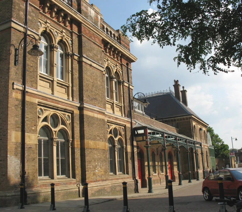




Pharmaceutical Pilot Plant for New Drug Development w/ Good Manufacturing Practices- Construction
Summary: JBM was project architect for this project for the entire duration of architectural services from design development to construction document completion.
This Pharmaceutical Pilot Plant was constructed in 2001. The project was led by a construction management team that required an architect to prepare design development documents for approval by the research client during a DD phase which immediately transitioned into a construction documentation phase.
In some of the earliest application of "building information modeling" John Millard embraced the process of predicting with great accuracy the location, quantity, purpose and nature of building elements that have an impact on each of the design disciplines. By closely cooperating with mechanical, electrical, structural and civil engineering team members throughout the process of building a detailed three dimensional model, John was able to incorporate these elements together into a single source of information- a parametric model of the building using Autodesk Architectural Desktop. This program has since been replaced and superseded by Revit.
Construction of the Large Spray Dry Space required milestone acquisition by the construction management team, but before these milestones could be achieved, accurate and effective systems required implementation by the design team. Fundamental objectives related to the room size, finishes, lighting, access and egress for fire or other human safety purposes were defined. Then, Good Manufacturing Practices related to the code compliance that exceed normal construction codes were specified. Finally, the systems that support those standards have to be physically accommodated and coordinated within a virtual/ computer model, then clearly printed in two dimensions with traditional construction conventions.
Background:
MBT Architecture was approached by a Pacific North West based construction management company to "be the architect of record" for a pharmaceutical manufacturing plant, otherwise known in the pharma trade as a "powder facility". The lead discipline for the project was the construction management company with the prime contract to construct a "tenant improvement" inside an existing metal building that was inexpensively acquired by the owner and asserted to be fit for the purpose for which they intended to operate inside the building. MBT agreed to a fee to perform the services of documenting a design that was conceptualized by another licensed architect who was a full time employee of the CM firm. Since the CM firm did not possess the manpower necessary to document the design, nor the insurances required to provide architectural services- the scope of work required of MBT Architecture was billed as a single phase construction documentation phase with no construction administration required by the prime contractor.
The Single Phase CD scope of work that became a defacto hybrid Design Development/ Construction Documentation effort (not good process):
The CM-employed architect who provided general arrangement plans to MBT had conferenced these GA plans with the owner of the research facility and obtained approval for those plans to be converted into construction documentation as part of the permit phase of the project. Acceptance of these plans by MBT was understood to be an owner approved document that was not only a functional adjacency diagram, but also encompassed sufficient space in plan and section in order to fit all of the user requirements as well as the additional space required by the mechanical/ electrical team's equipment. As it turned out, the general arrangement plans were very close to the final plans with the exception of a 12" discrepancy caused by a measuring error when the interior clear dimensions of the existing metal building envelope were incorporated into the survey notes by the CM team. This error was reportedly caused by the use of a special civil engineering measuring tape that for some purpose had an additional 12" of tape printed on the end. The measuring team were apparently unaware of the additional 12" to be compensated for when recording their measurements. Unfortunately, this error was not uncovered until construction teams equipped with measuring tapes were verifying measurements in the field in preparation for installation of the first packages of concrete. The 12" discrepancy was reported to the CM and the CM instructed the architect to "find 12 inches" in the 80% construction documents that had been printed and were used to procure initial concrete placement contracts. As it turned out, at this late stage there was no obvious source of wasted space from which the entire building could be shortened and narrowed (both north/ south overall dimensions and east west overall dimensions). It then fell upon MBT to provide a cost to the CM to pay for the design effort that was required to identify sources of space in plan that would be subtracted from in order to make the construction documented design fit inside the erroneously measured existing building.
As stated above, the complex three-dimensional model that was developed in collaboration between the architect, the mechanical engineering team, the structural engineering team, and the owner was inclusive of all of the mechanical, electrical, plumbing and architectural openings in all of the walls of the proposed design. These openings and other court needed features of the design were documented in the 80% of construction drawings that have been issued prior to being notified of measuring error made by the construction management team. In order to subtract 12 inches from various locations within the proposed plan, the Spaces that would suffer from the deficit of 12 inches or some part of those 12 inches would have to be approved by the owner for reduction. It may sound like a simple exercise, shrinking the building into taxis by 12 inches–but as it happened there was no one single space across the entire width or length of the building that we could stretch this 12 inches out of. The 12 inches had to come from a complex some of dimensional decreases in the plan that would be acceptable to be owner. Consequently, the Computer aided design operations that were required in order to compensate for these dimensional changes to plan where quite time-consuming and required a great deal of court nation with components of the drawing package that we're not interactive with the three-dimensional model. At the time, Autodesk architectural desktop release three produced interior elevations and reflected ceiling plan that we're static electronic files that stood separately from the three-dimensional parametric model that defined the volume of the spaces. Therefore, when three or 4 inches was subtracted from a specific space, all of the wall openings and the reflected ceiling plan were affected. While the parametric model was extremely useful in accommodating these changes, the disconnected drawings some of which required updating and some of which did not require updating-had to be manually coordinated and corrected in a very time-consuming exercise that cost a great deal of additional money. It turned out to be an estimated 90 hour effort to subtract the 12 inches from the length and width of the building.
Fortunately for the mechanical engineering team, they had not begun the final duct design for the mechanical scheme because they suspected that additional changes may be afoot. Once the changes to the dimensions of the building were completed and all of the Wall openings were coordinated with those changes, the mechanical engineer could begin his final duct design which employed a parametric mechanical engineering modeling System called Pro Engineer. The corrected and coordinated three-dimensional model produced by John Millard was exported to the Mechanical Engineering Firm, Holiday Parks where the final duct design was incorporated and coordinated with the structure. In many cases, the lack of vertical space required by the mechanical equipment located above the functional spaces required variances in head height for maintenance and operation of the equipment. "Ducking" one's head under the steel beams that supported the roof structure became a necessary solution to lower head heights in the mechanical spaces and in some case, it was arguable if these travel routes were acceptable to the fire officer.
Early example of BIM was carried out with disparate tools by disparate disciplines. (Architectural Desktop / ProEngineer)
With John Millard at MBT using Auto-cad Architectural Desktop R3 and Mechanical/ Electrical Engineers at Holiday Parks using Pro-Engineer, a disconnect existed between the three dimensional models maintained by each team. Nevertheless, a high degree of transparency between the teams resulted in a close cooperation based on frequent updates of the respective models for coordination purposes. Mechanical openings in walls were the primary responsibility of the architect to closely follow the instruction of the M.E. for the location, size and specification of each opening. Export of the three dimensional model to the mechanical engineer would provide review and comment process to adjust for any revisions to openings. Likewise, the architectural model became a source of data for intelligent schedules of openings as well as windows, relites, doors and other typical architectural components such as casework, fittings and fixtures. This was made possible due to the library of intelligent objects that Autodesk and other sources (Ketiv) created for the Architectural Desktop Object Enabled Software. As the walls, doors and window openings were modeled into the architectural model, interior elevations would be created automatically using elevation tools in the software. The process of review and comment of these room by room developments of the mechanical, electrical and plumbing components were transposed initially by the hand drawn markups of the M.E. then incorporated ingot he model by the architect and checked for conflicts, accuracy and certainty in the next exchange of data by export of the three dimensional model and associated reflected ceiling plans and interior elevations.

As early as 2001, John Millard was an advocate for Building Information Modeling. The drawing above is evidence of a three dimensionally coordinated pharmaceutical powder plant governed by Good Manufacturing Practices (GMP). John Millard was the Project Manager of this project and remained in this role from inception to completion of the construction.

This Pharmaceutical Pilot Plant was constructed in 2001. The project was led by a construction management team that required an architect to prepare design development documents for approval by the research client during a DD phase which immediately transitioned into a construction documentation phase. The Architect of Record was Peter Hockaday of MBT Architecture yet MBT, the firm that JBM was employed as Project Architect on this project was not mentioned in the title block of the drawings. This was apparently at the direction of the construction management company in order to reinforce perception that the CM was the lead discipline on the project for marketting purposes
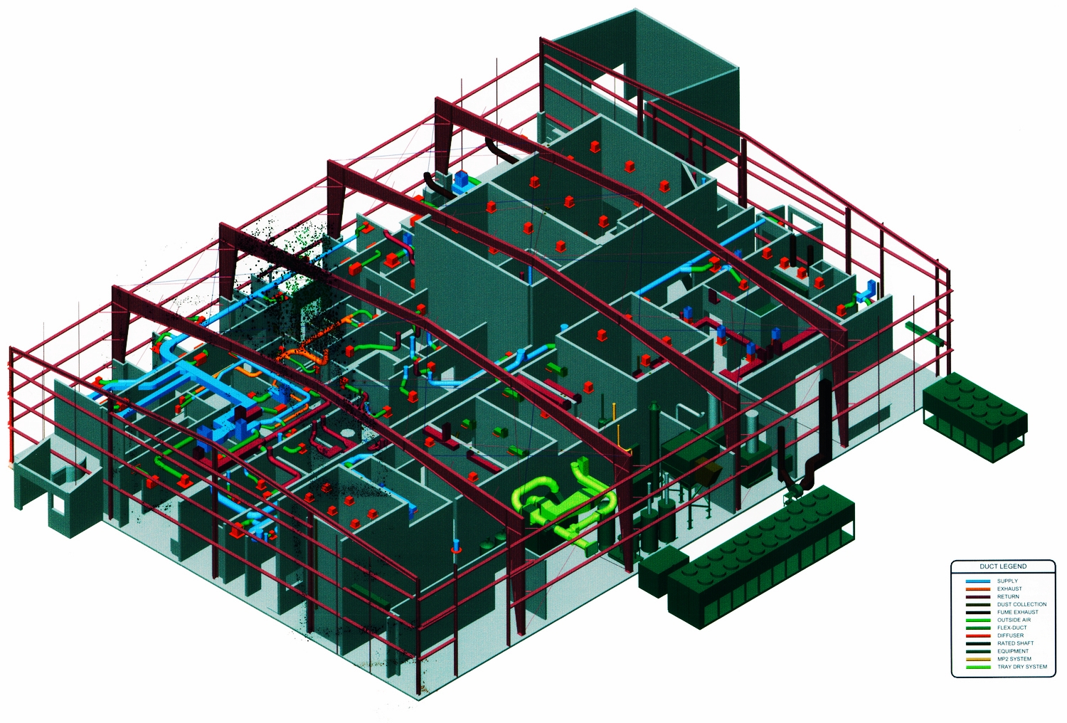
The metal framed industrial shell that became host to the pharmaceutical powder facility proved to be a close fit for each discipline to complete their respective designs. The mechanical engineering component of the overall scheme faced the greatest challenge, servicing the process equipment in each space with plumbing, heating, air conditioning and air changes that demanded only the purest air and plenty of it in order to manufacture the pharma product using GMP.
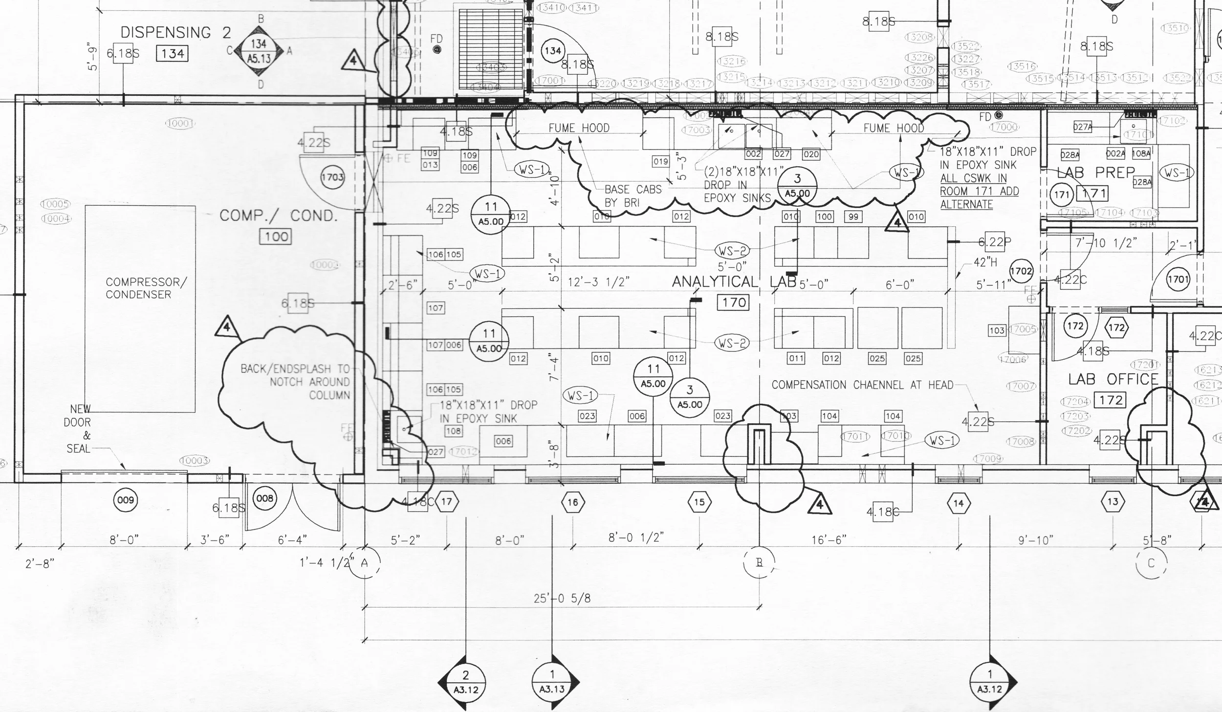
While most of the building was effectively a laboratory full of equipment, the analytical laboratory was equipped with fume hoods and laboratory benches, fittings and fixtures but was not a heavy research lab. The analysis of pharma product from the powder processes is the primary mission of the analytical laboratory.
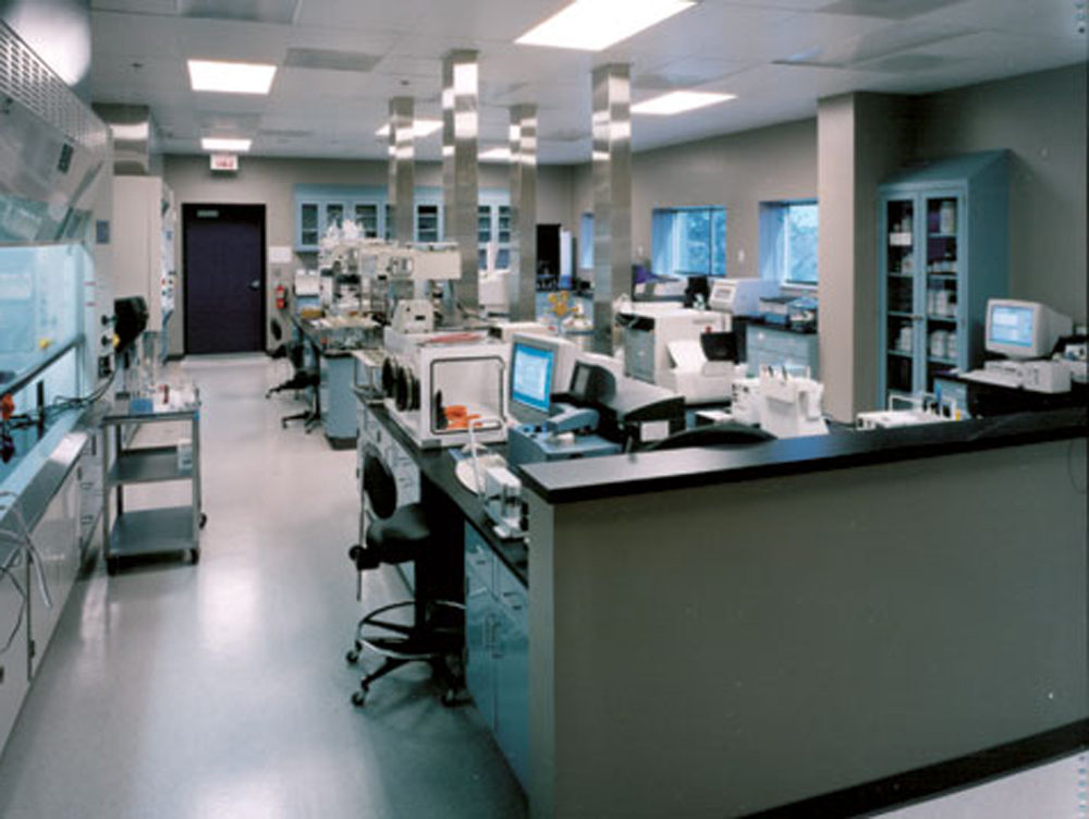
As can be seen in the photo, the laboratory benches were essentially desk height worktops without shelves or upper casework and plumbing/ electrical drops to service the computers and wet applications on the central island bench. The fume hoods (to the left in the photo) adjoined the Large Spray Dry spec which had return air grilles in the wall.
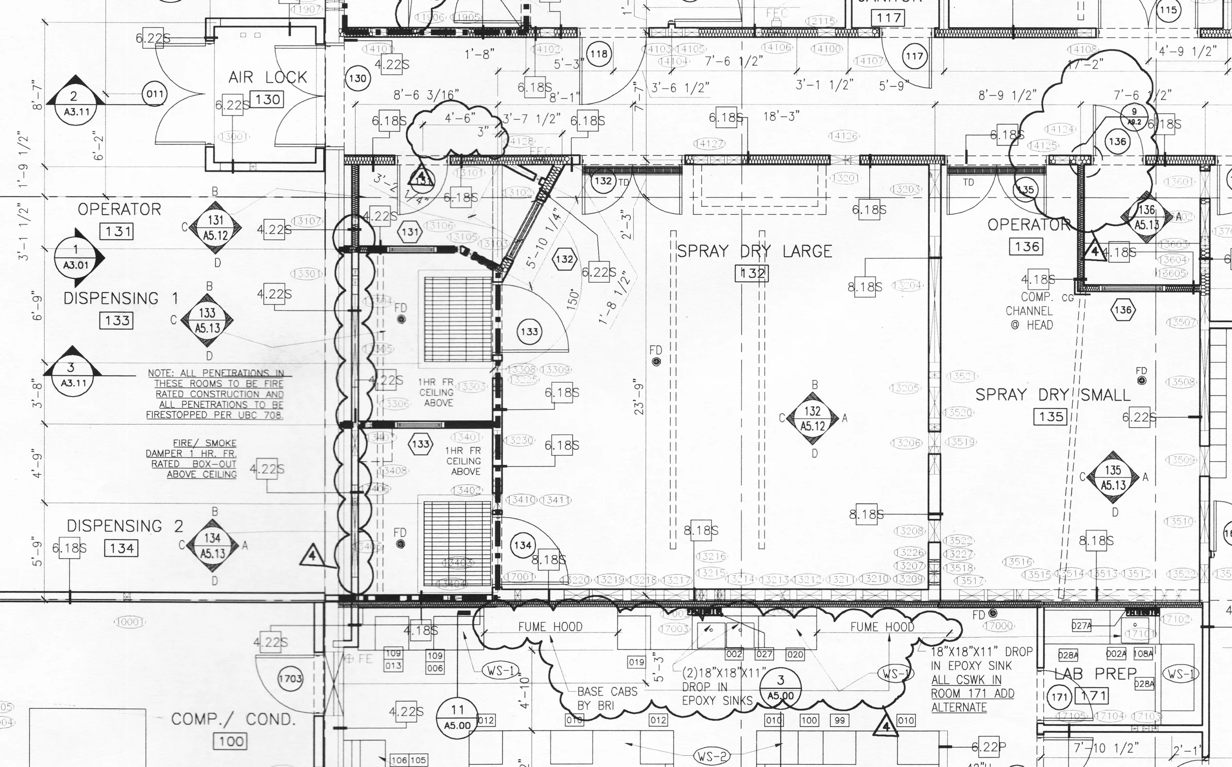
The large spray dray equipment required a high degree of air change in order to comply not only with GMP but also with OSHA. The particulate matter that could accumulate in the air of the room requires special filters and other personal safety measures that make coordination of all electrical, mechanical and plumbing services a multiplicity of tasks.
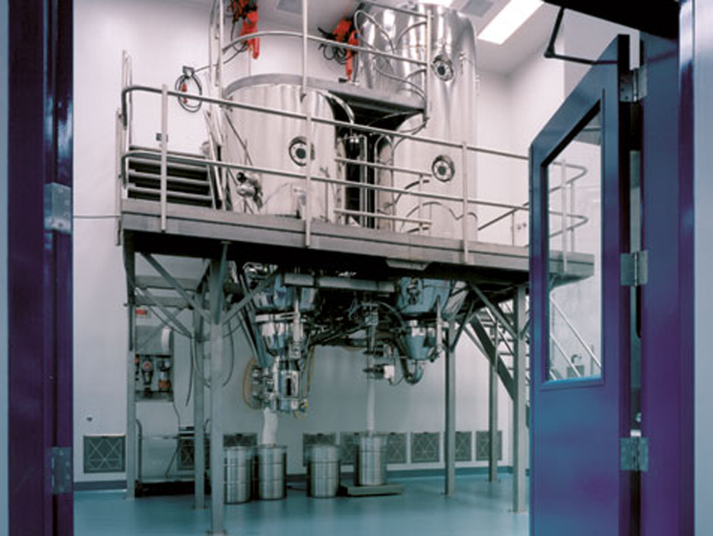
Spray drying is a method of producing a dry powder from a liquid or slurry by rapidly drying with a hot gas. This is the preferred method of drying of many thermally-sensitive materials such as foods and pharmaceuticals. A consistent particle size distribution is a reason for spray drying some industrial products such as catalysts. Air is the heated drying medium; however, if the liquid is a flammable solvent such as ethanol or the product is oxygen-sensitive thennitrogen is used.[1] (Wikipedia)

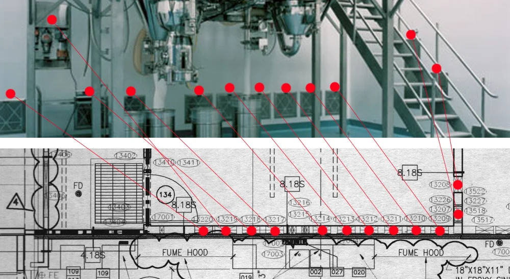
In this example of three dimensional modeling, where the model displays as a two dimensional plan, showing typical plan features for registration by a constructor- all of the openings required by the mechanical engineer to ventilate this GMP space are shown in plan in addition to the traditional architectural openings of doors, windows and relites. Here, the openings shown in plan are reflected in an "as-built" photograph (mirrored for clarity).
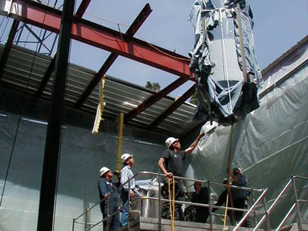
Construction of the Large Spray Dry Space required milestone acquisition by the construction management team, but before these milestones could be achieved, accurate and effective systems required implementation by the design team. Fundamental objectives related to the room size, finishes, lighting, access and egress for fire or other human safety purposes were defined. Then, Good Manufacturing Practices related to the code compliance that exceed normal construction codes were specified. Finally, the systems that support those standards have to be physically accommodated and coordinated within a virtual/ computer model, then clearly printed in two dimensions with traditional construction conventions.

The metal structure that contains the GMP Facility pre-existed the design of the facility itself. This approach of dictating the volume and shape that the future facility should conform with- is not a process that served the finished design product or the construction process well. This was not caused by the these teams but by the inception and perception of the project being a "retrofit" project that would cost less if inexpensively procured by purchasing an existing structure as opposed to purchasing a new construction. It remains to be seen if this approach to the project was more or less costly.

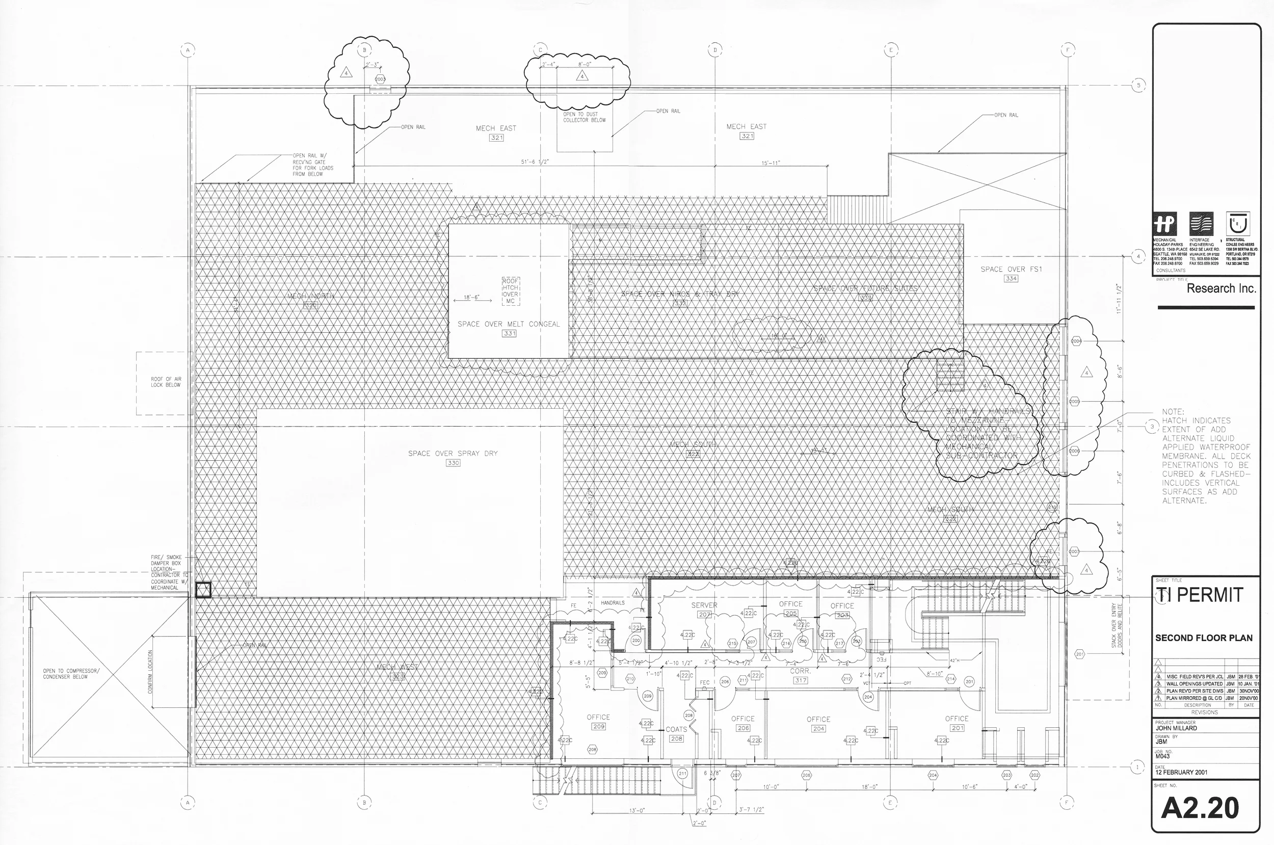

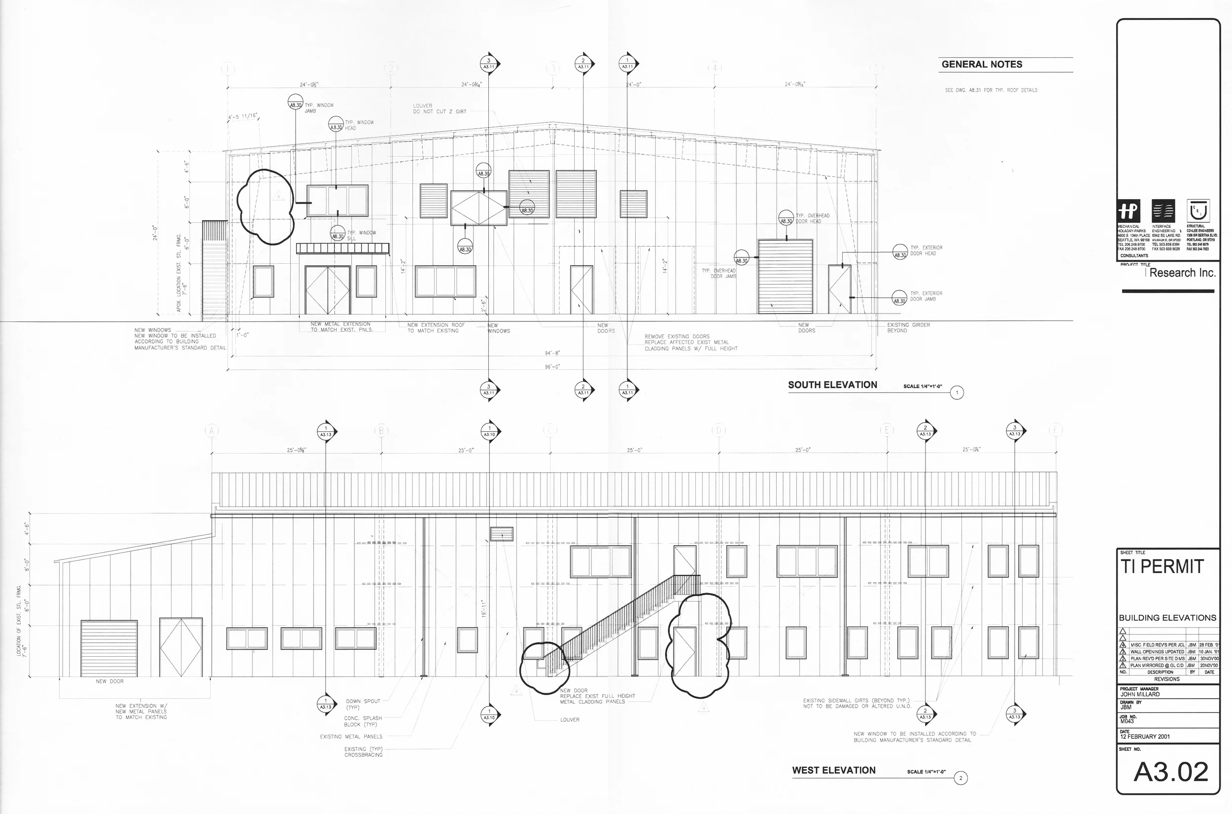

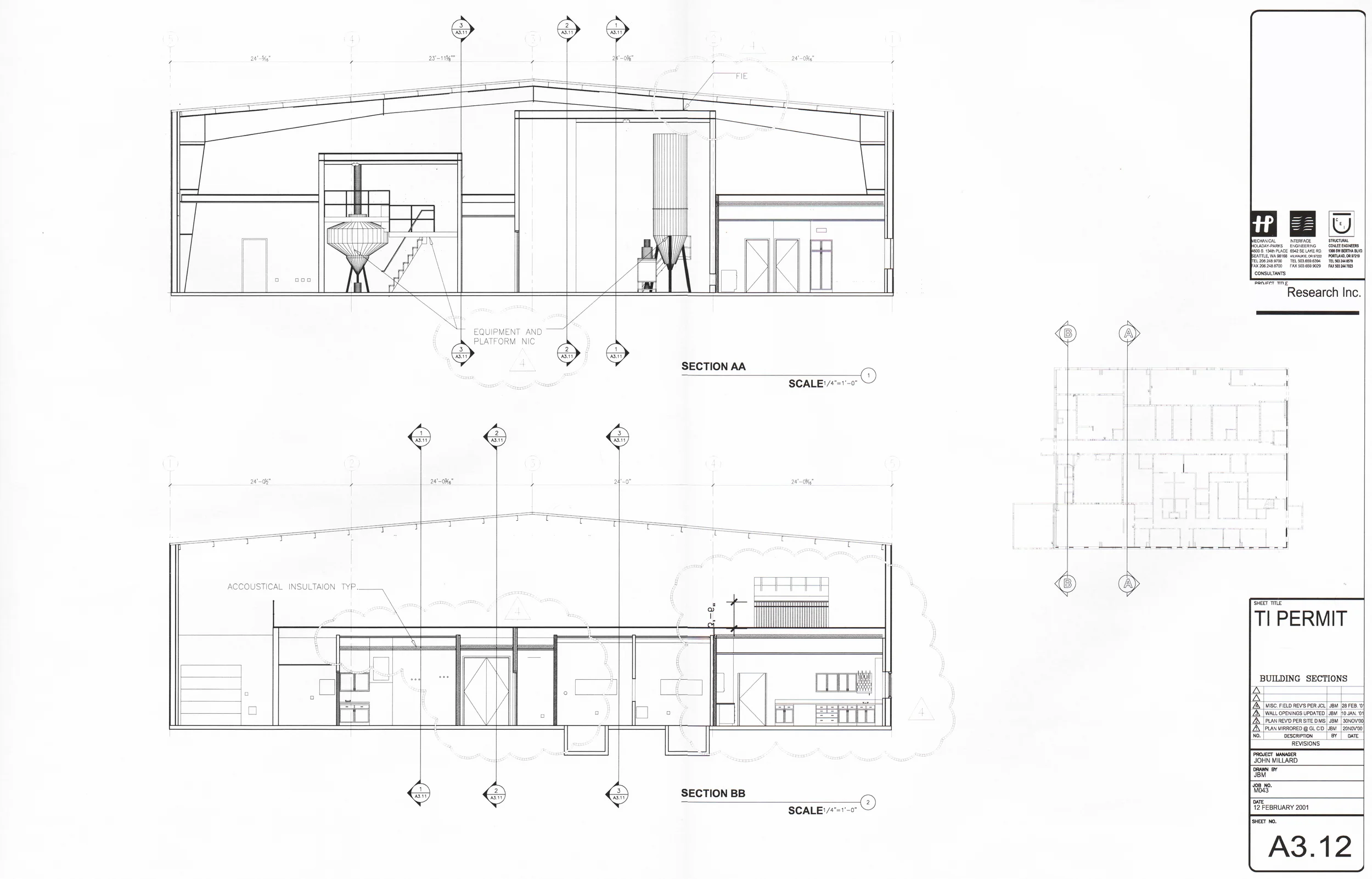

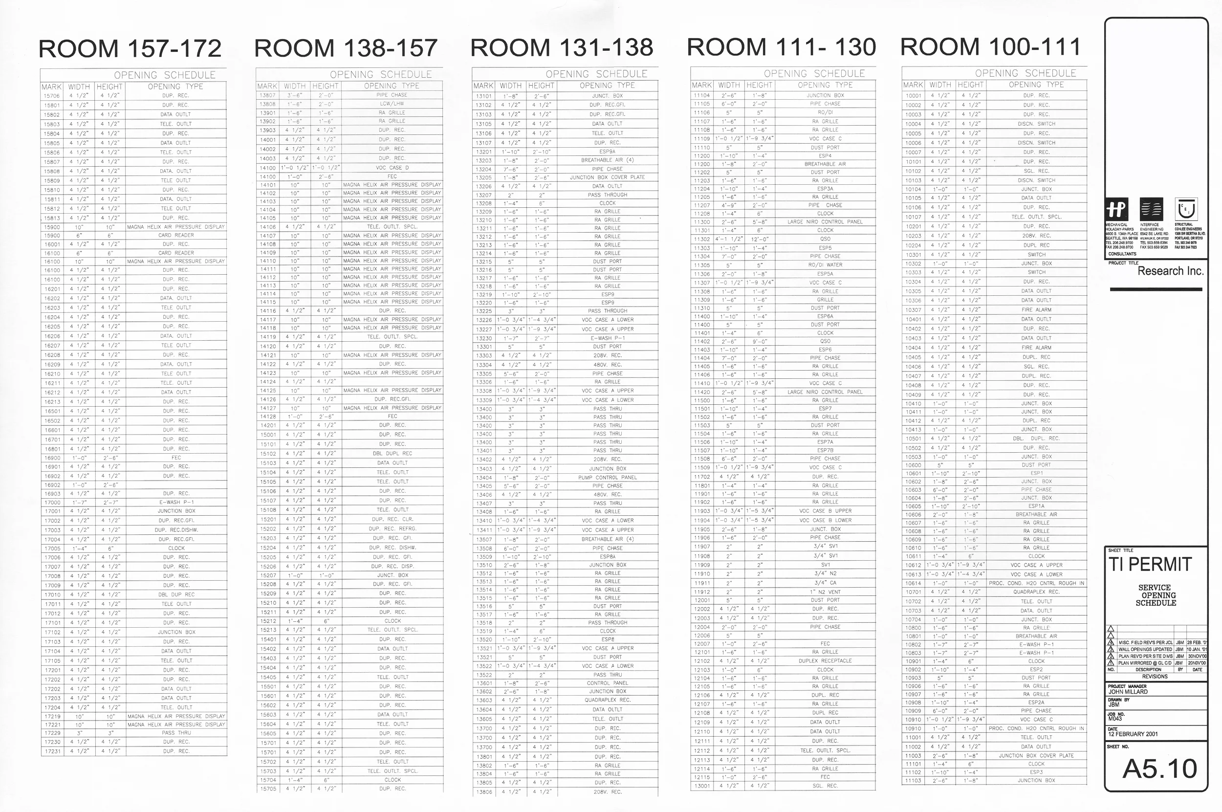
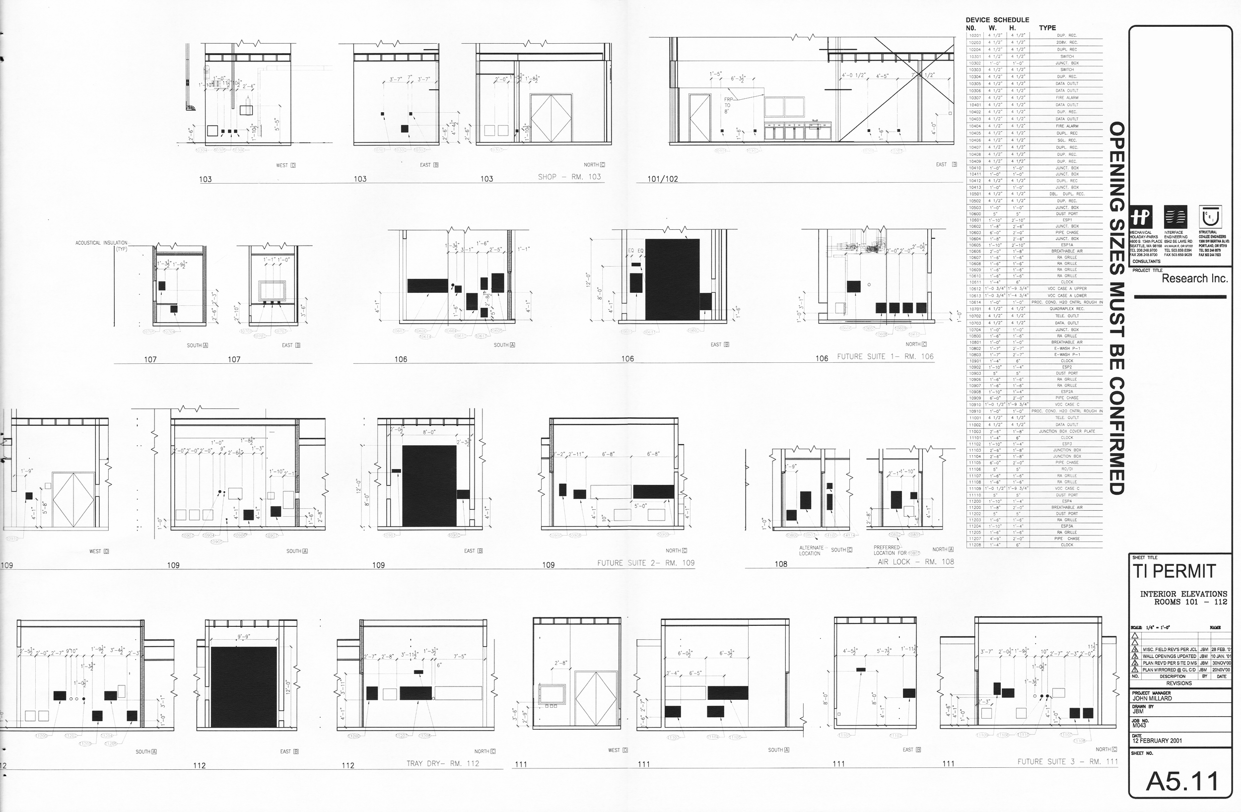
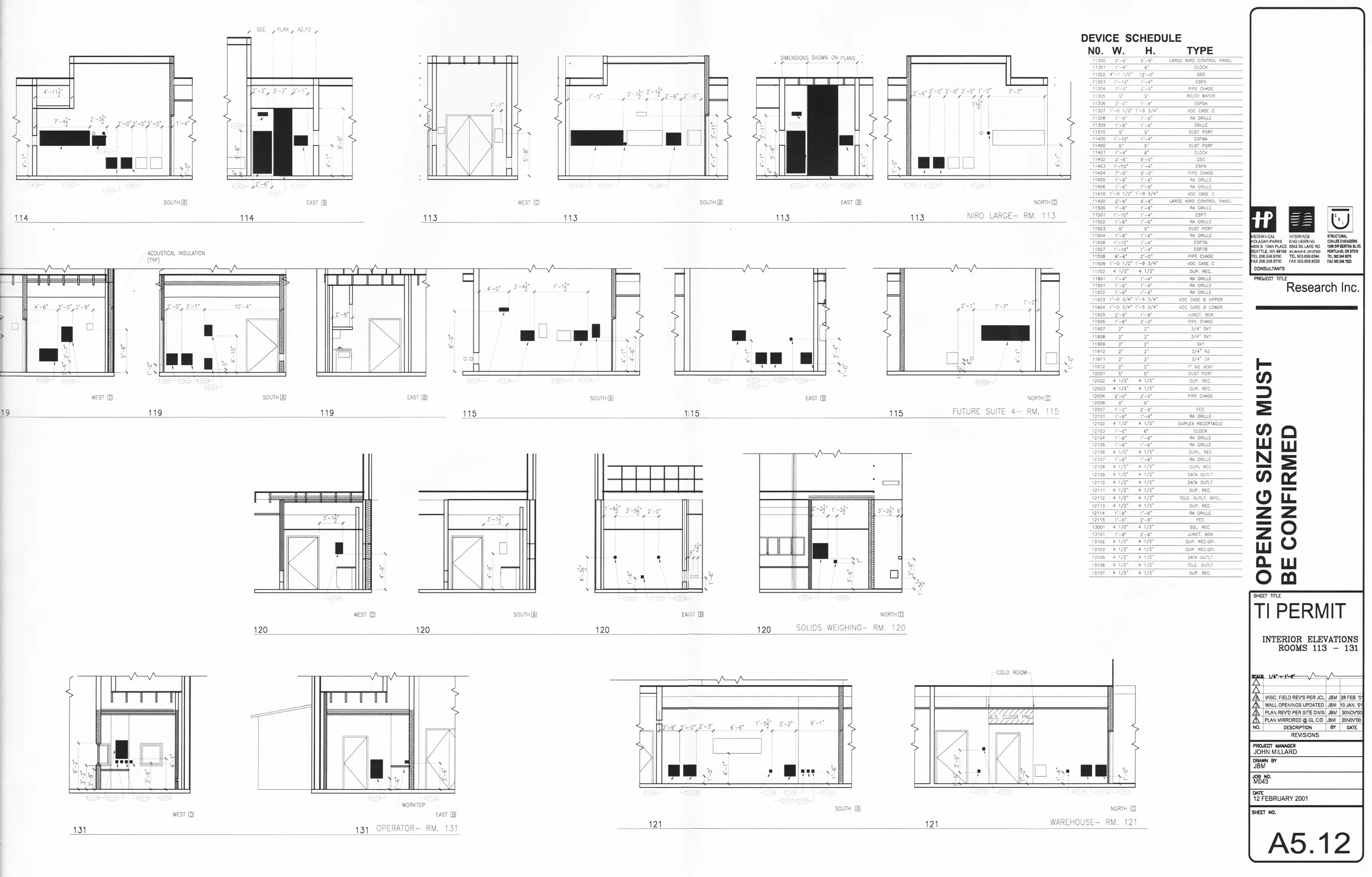
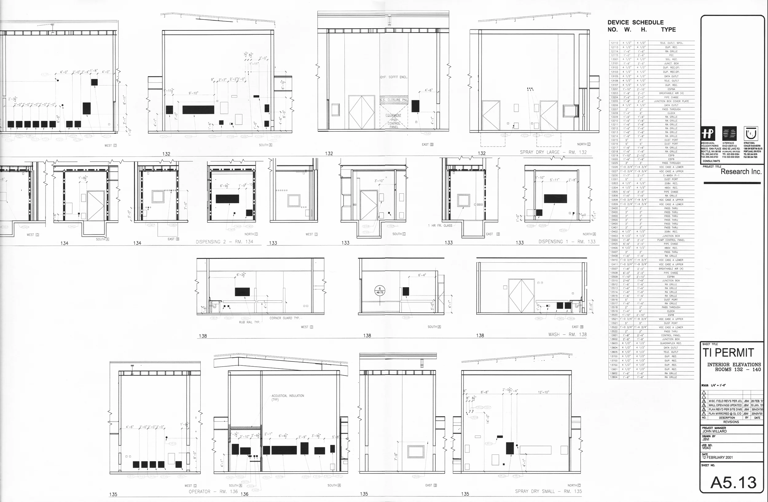
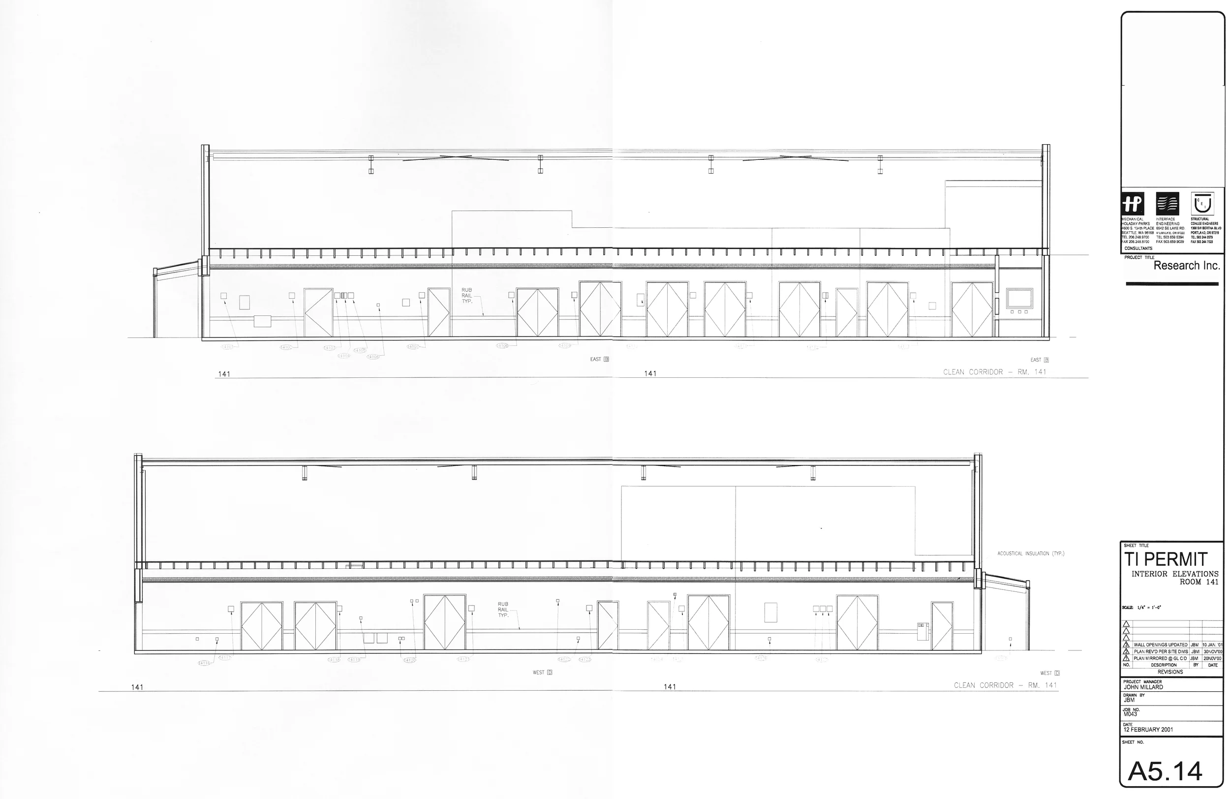
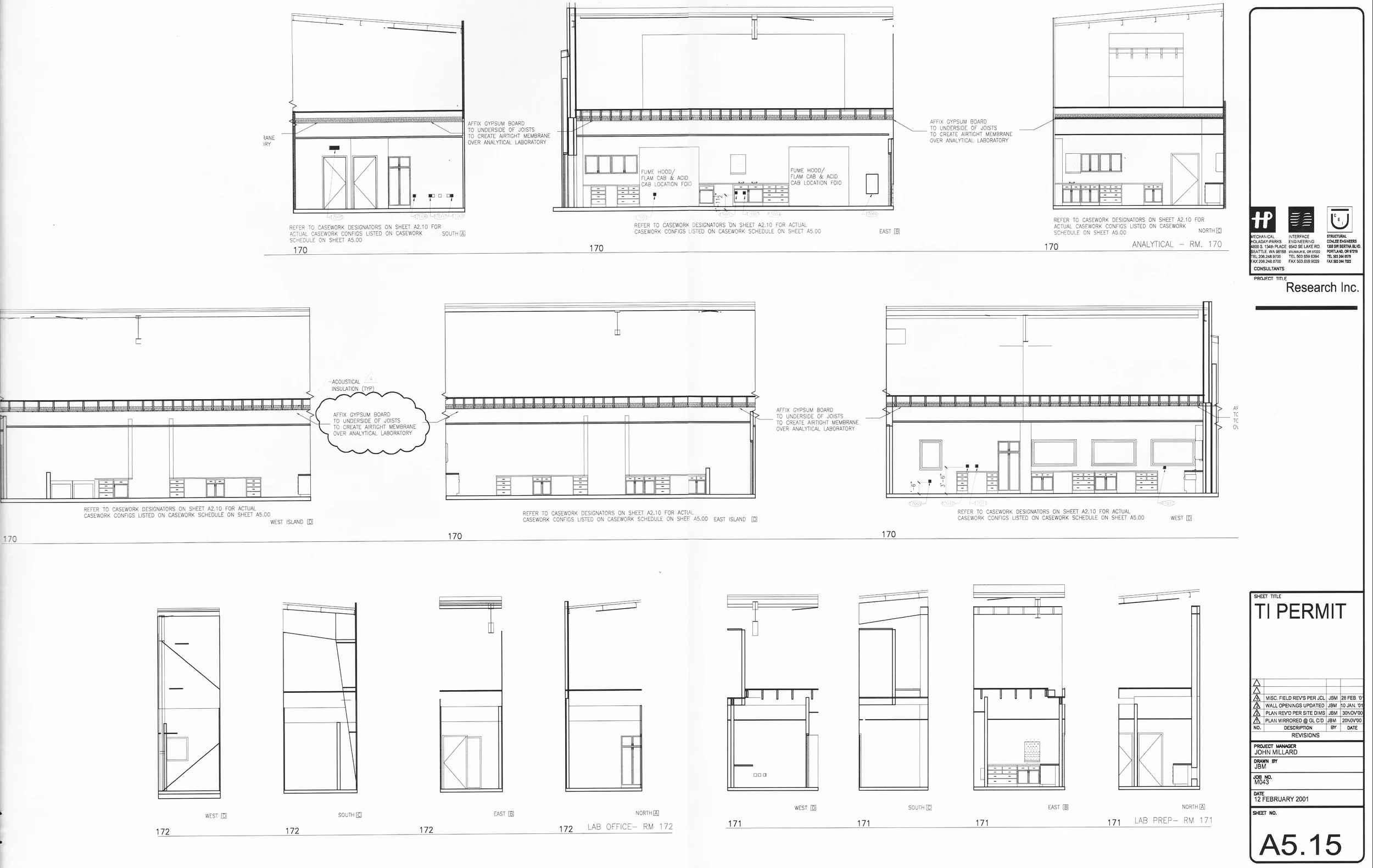
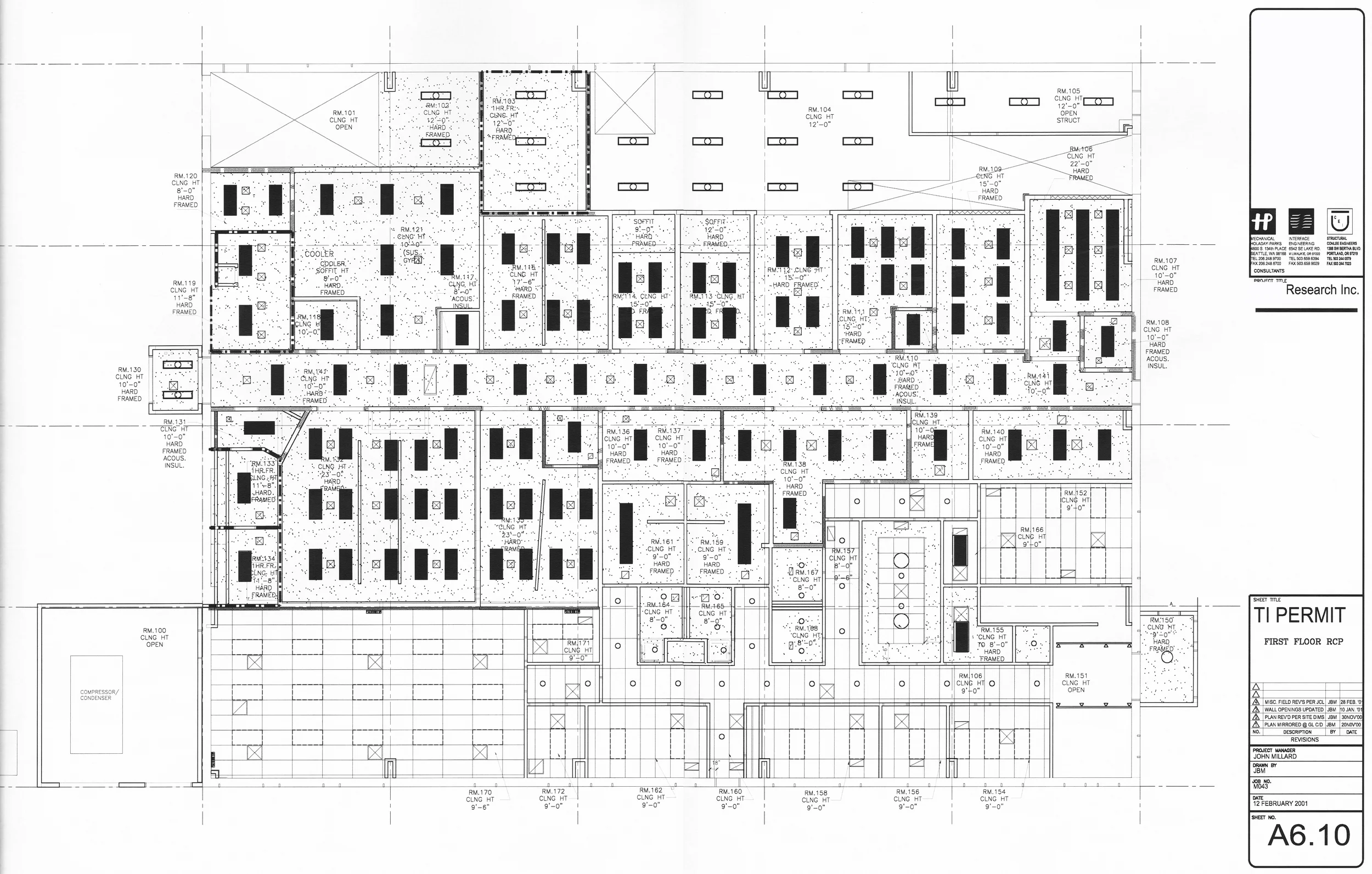
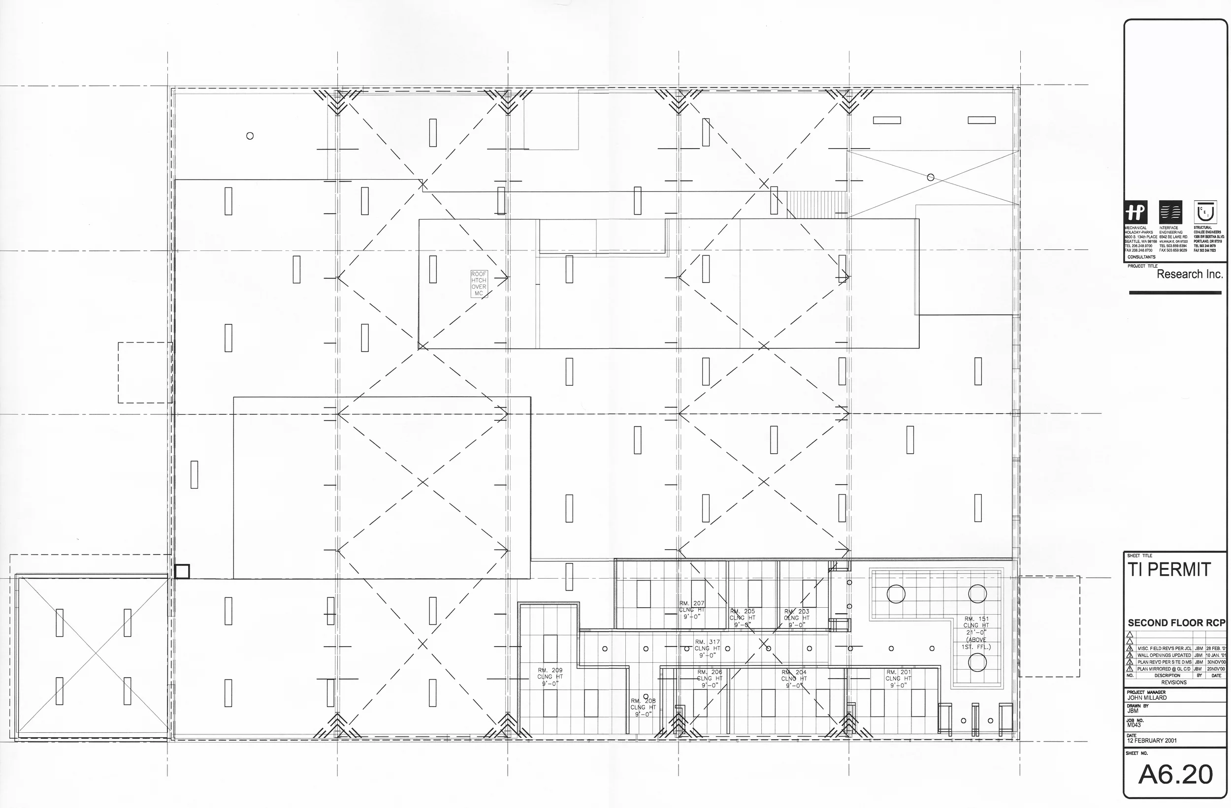
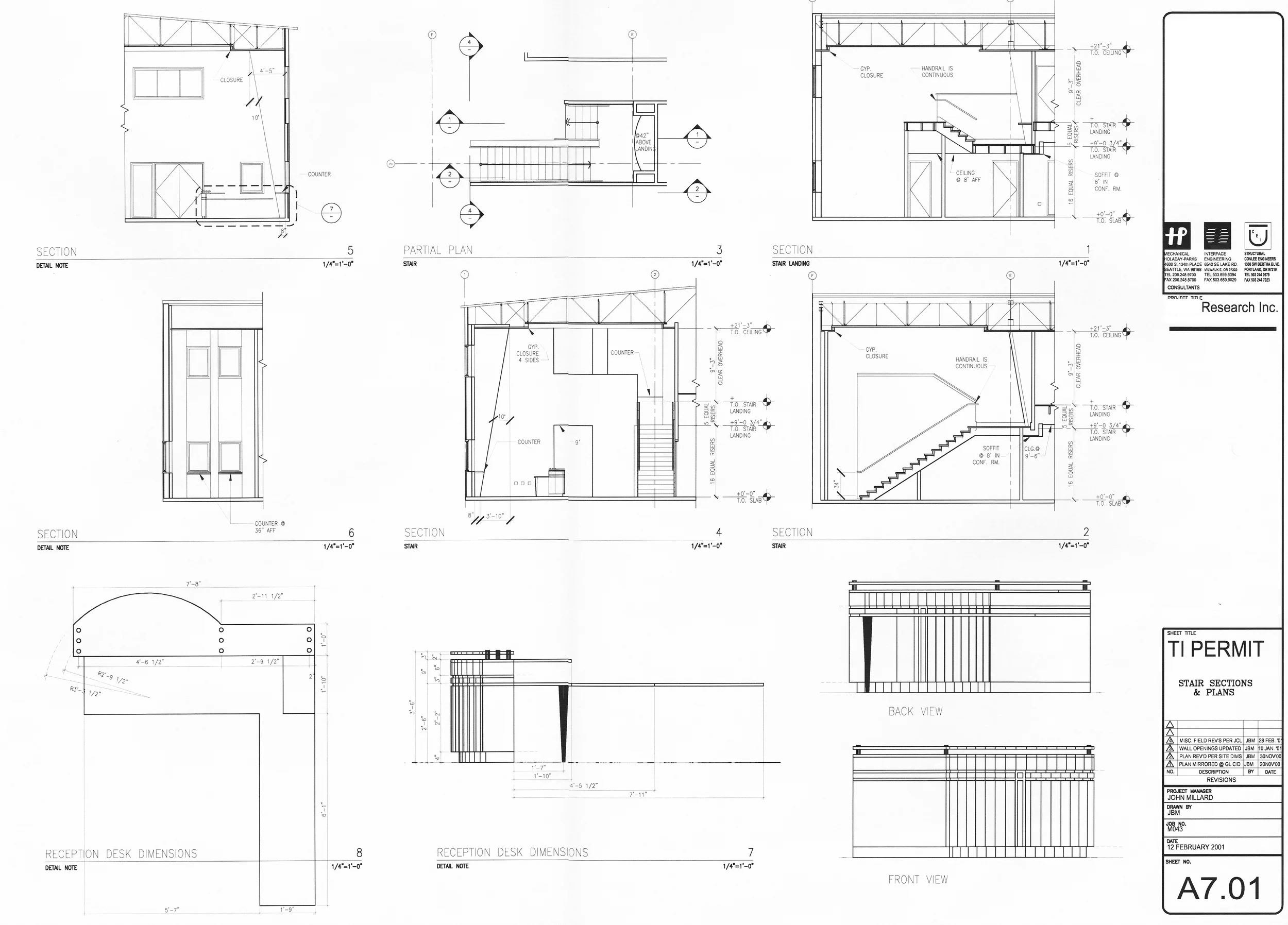
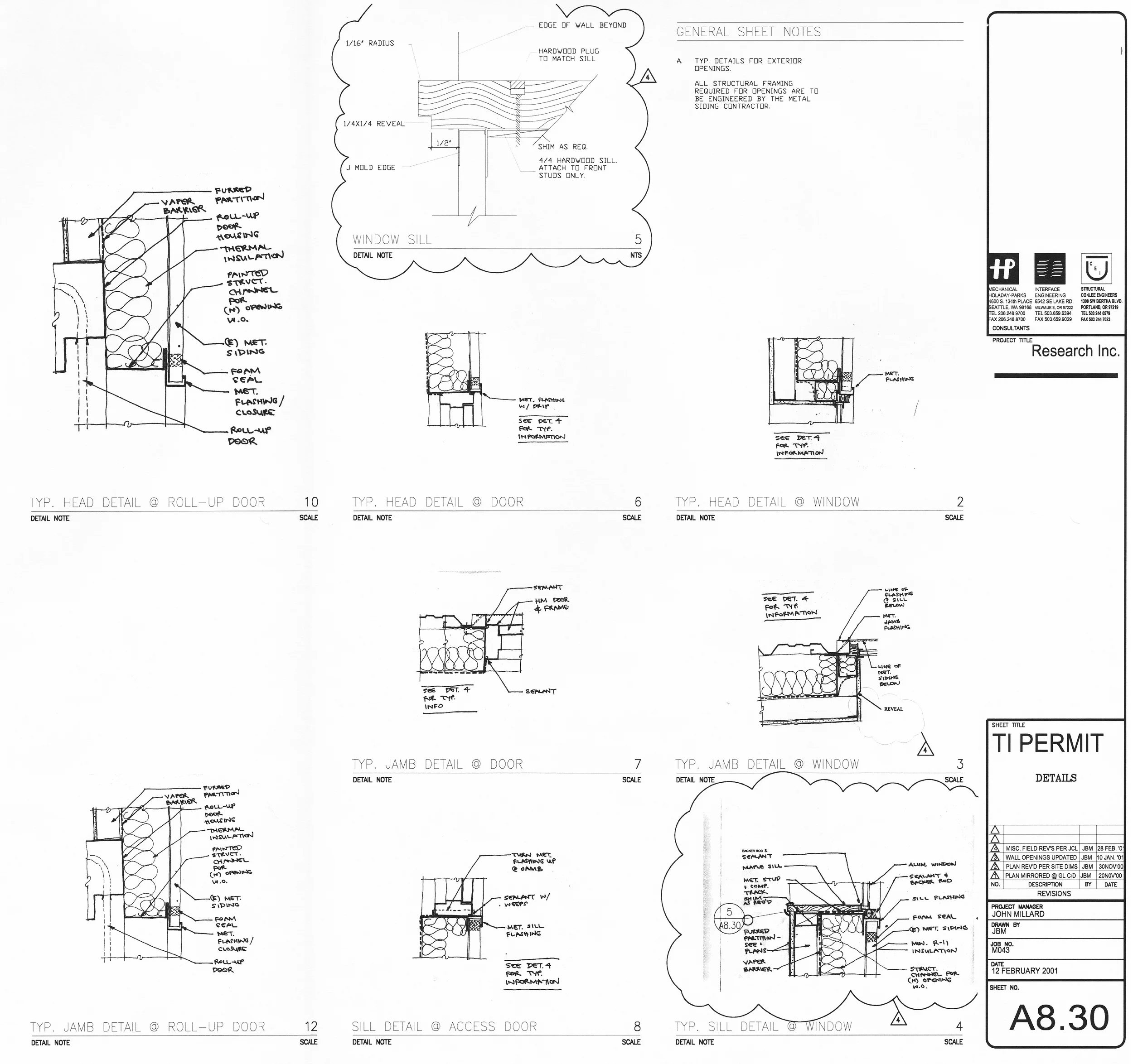
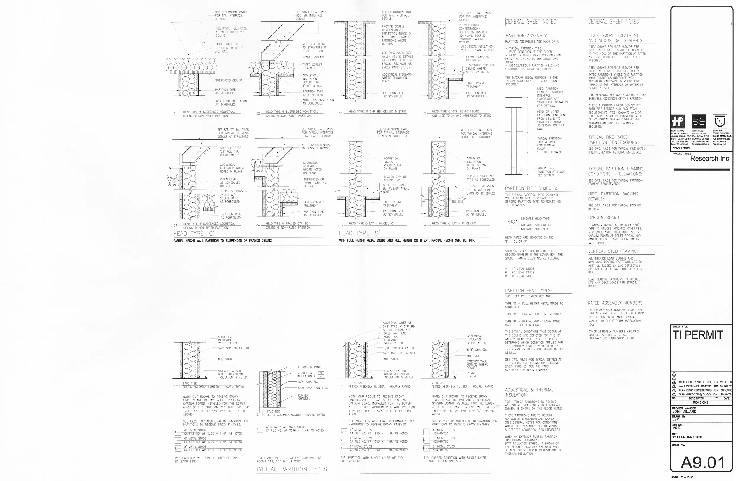
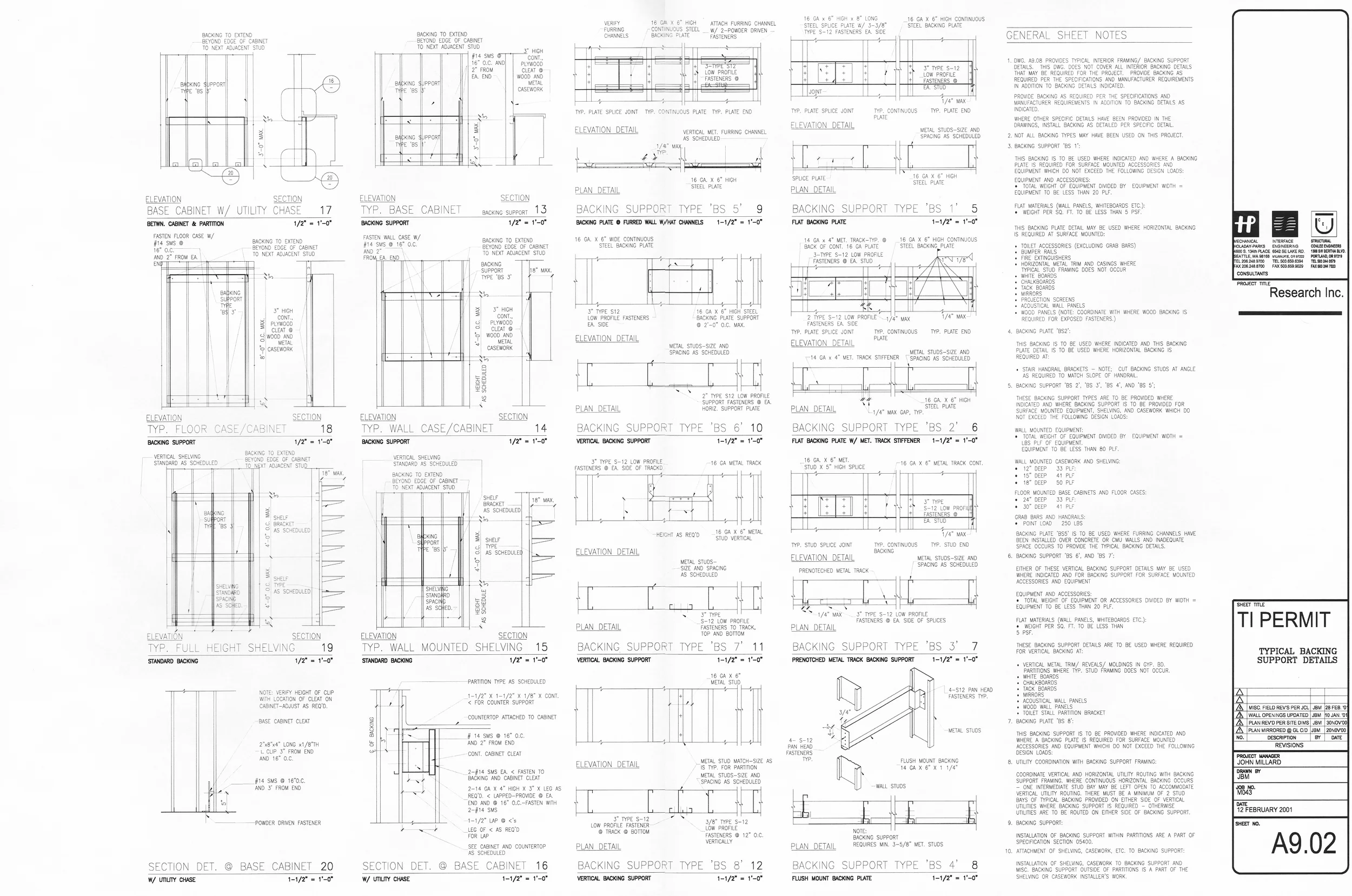

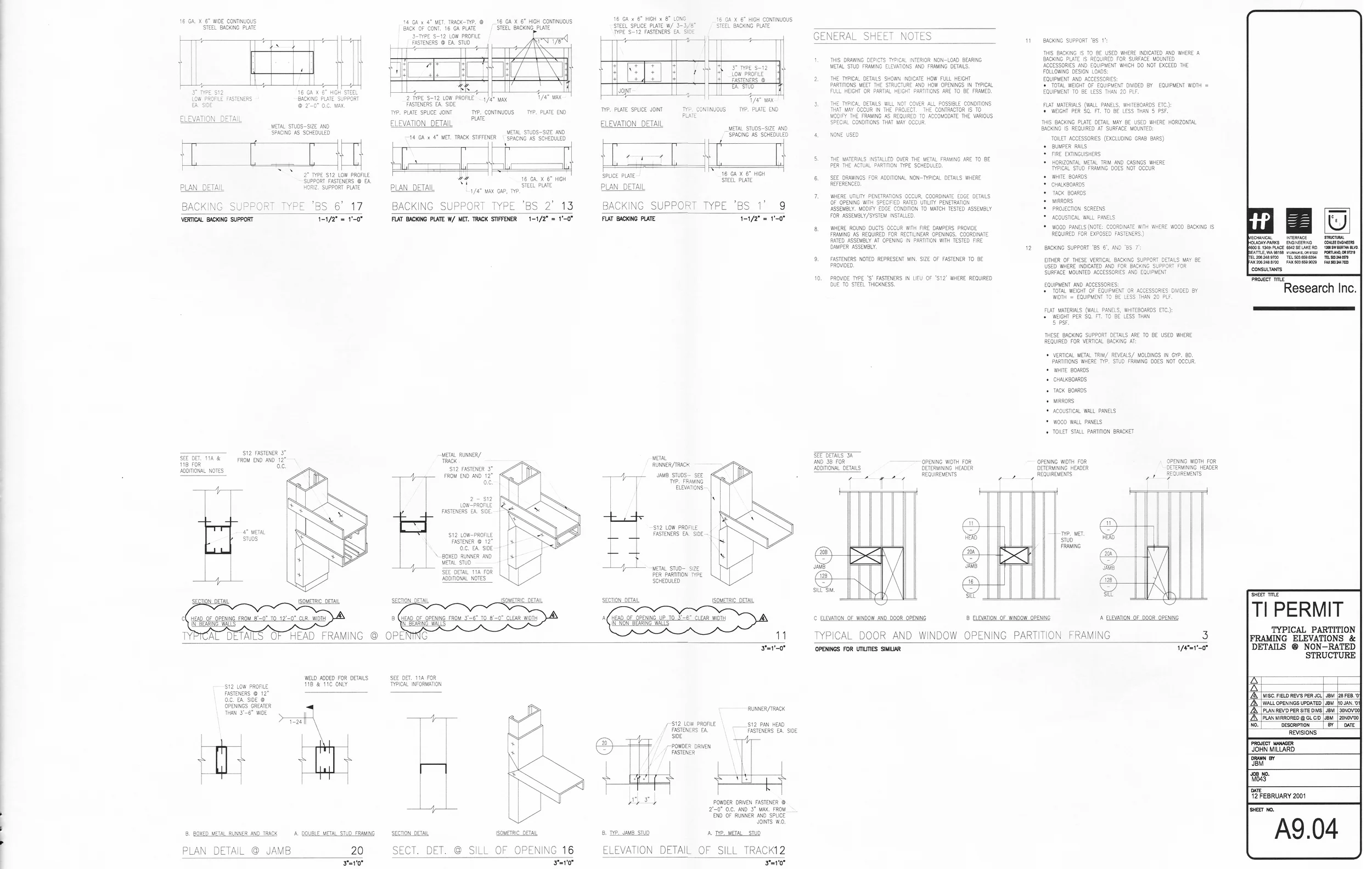
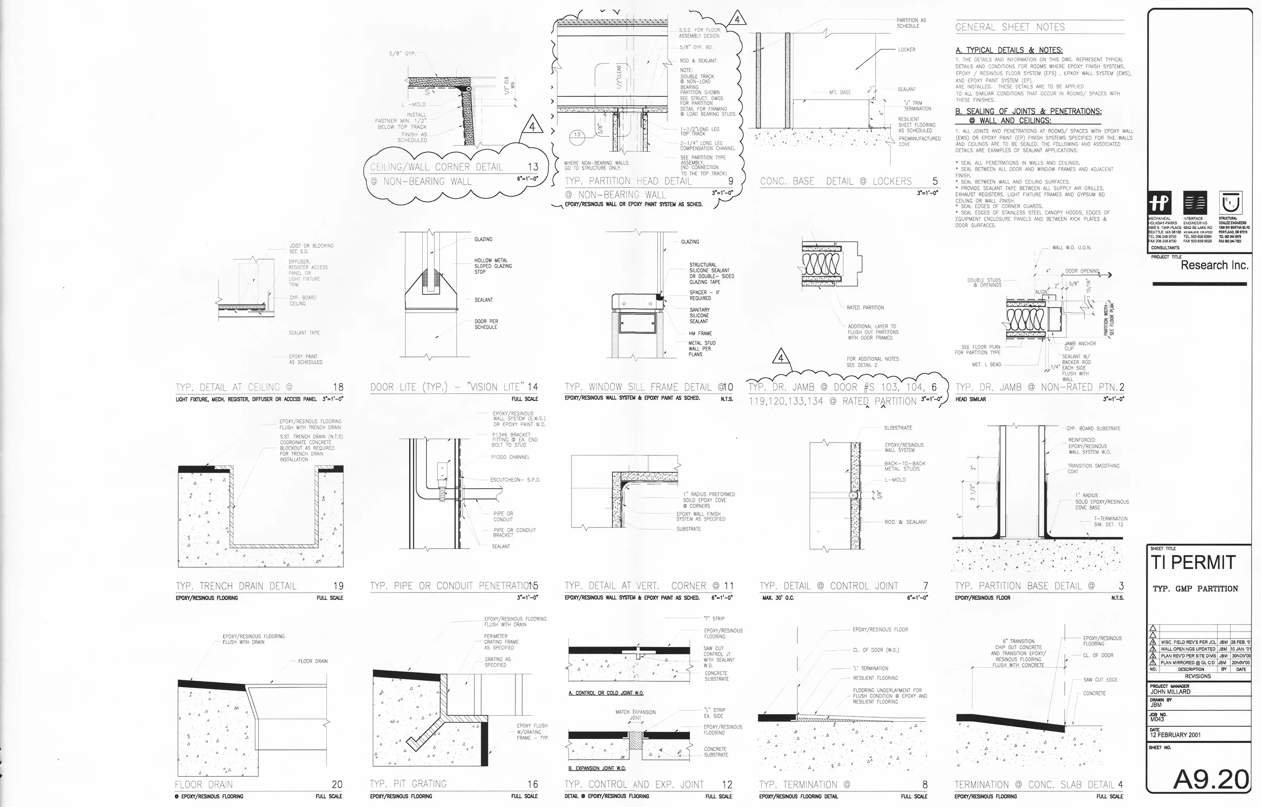
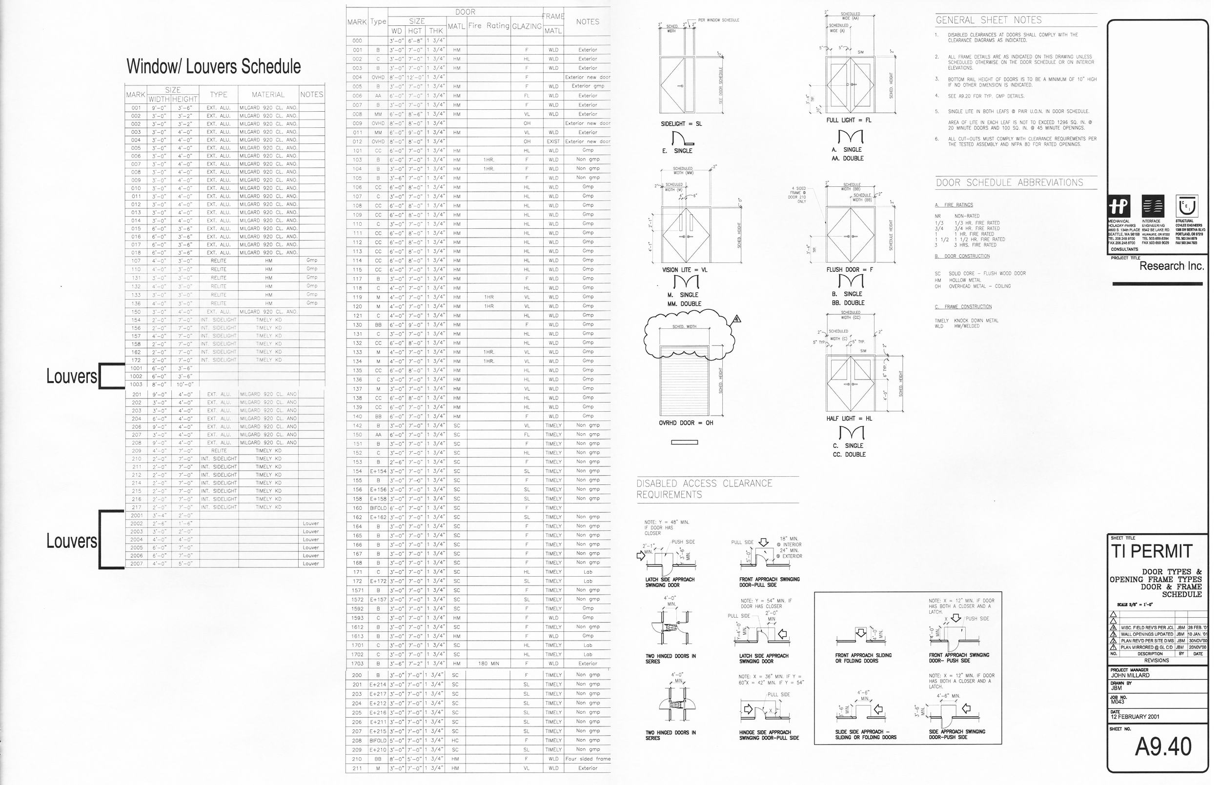


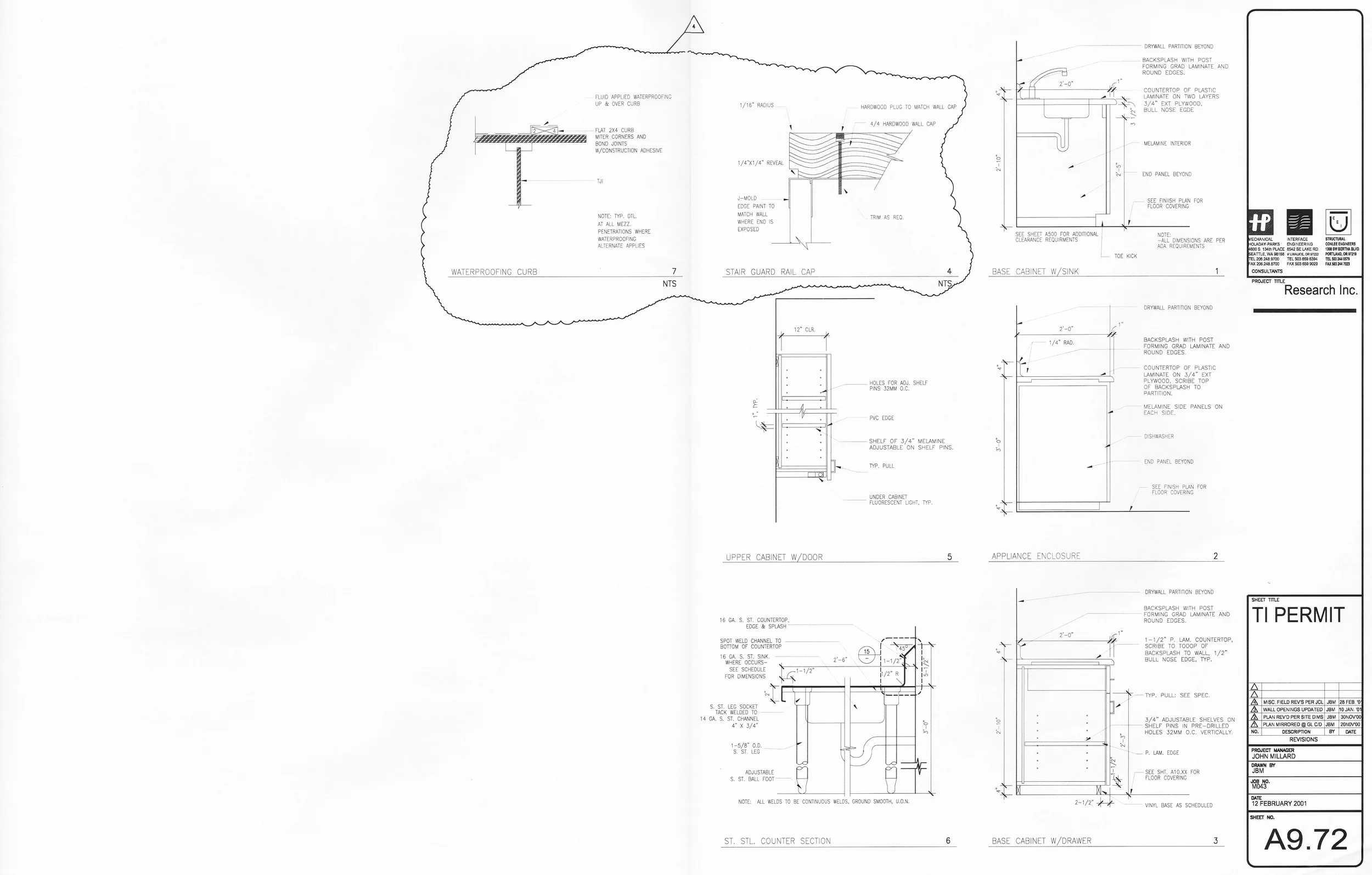
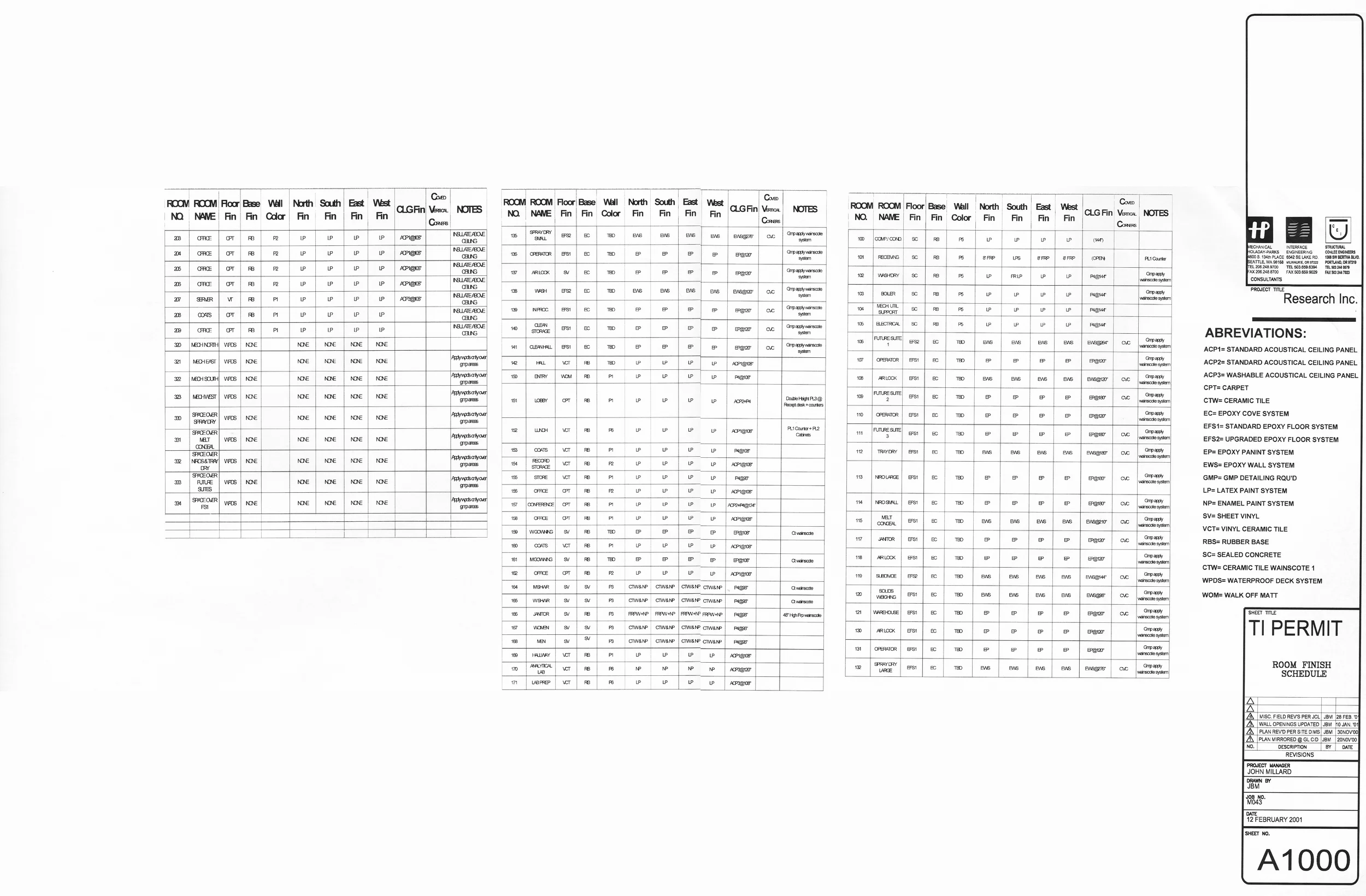
Institute for Mind, Brain and Learning in Seattle, Washington- Formulation Study
Architecture Firm: MBT Architecture
Client: McCaw Foundation
Site: University District, Seattle
Date of Project: 2001
Project Summary:
Summary: JBM's role on this project in 2001 was: to provide a formulation study of the programming issues together with the principal architect, Peter Hockaday, produce a conceptual design package of drawings and models over several options, prepare a programming/ concept design formulation study and present the concepts to the client user, The Center on Human Development and Disability at the University of Washington.
John Millard's Role: Project Architect for Formulation Study
Specific Role by John Millard: 1)
Duration of Design Effort: January 2000
Introduction
The ultimate goal of architecture is to give shape to ideas, to provide form to concepts; in other words, to craft physical spaces that achieve the purpose intended for them. This study is the beginning of this process for the Center for Mind, Brain and Learning. It is the "formulation" of the issues, spaces and concepts which will provide the basis from which the future design of the Center will take shape. The founders of the Center have identified three priorities or concepts that the built form shall provide. The first priority is that it be an INTER-disciplinary place that fosters and encourages interaction and collaboration between disparate types of research and researchers. Secondly, ' it should be a public friendly place which provides spaces for the general public to interact with, contribute to, and benefit from the research being produced in the Center. Thirdly, the facility should be a functional and adaptable place to think that allows the researchers to do the work they need to do and to allow them the places where they can do their research and formulate their ideas.
Each of these priorities can be broken down into a number of components which can be expressed and addressed by the architecture of the facility. This study begins the process of design by identifying architectural concepts of these compo- " True learning is only achieved in nents. good company." The first step shall be to identify the types, size and amount of spaces required to meet the functional requirements of the Center. The second step will begin to suggest the relationships of key spaces to each other as well as the quality of the spaces involved. The final step will take the results of the first two steps and merge them into a number of alternative concepts for the Center. These concepts will be rough massing studies that will begin to suggest organization and three dimensional relationships of the spaces to each other and the potential site which at this time is undetermined.
SPACE LIST
Space/ Department Descriptions/ ASF/ Quantity/ NSF/ Sub-total
Adminstration Executive Office Co-Director 400
Co-Director's Secretary 120
Institute Administrator 240
Administrative Assistant 120
Fiscal Specialist 120
Receptionist 100
BoardRoom 500
Waiting Area 200
2,840
Research Transfer Staff Business Liason 160
Business Transfer Assistant 120
Technology Transfer 160
Education Liaison 160
Education Liaison Assistant 120
Public Outreach 160
Product Consultants 400
Conference Room 240
1,520
Administrative Support Kitchen / Pantry Area 240
CopylWorkroom 160
MailRoom 200
File Room 200
Public / Meeting Space Break-Out Rooms 240
Auditorium / Projection Room 2,600
Cafeteria / Kitchen 3,000
Main Lobby 400
Adult Waiting Area 400
Children;s Waiting Area 400
Coat Room 50
Vending Area 150
Public Rest Rooms 300
Library 3,000
Fitness Center 2,000
13,130
Research
Lab Space
(includes researcher's offices)
Core Facilities / Lab Support
Experimental School
Brain Wiring and Plasticity
Technology and Learning
Molecular Biology
Early Learning
Visiting Scientist's Offices
NeuroCore
MRI and support
MEG and support
Offices
Computing Core
Stat Analysis Core
Instrument Core
Media Core
Molecular Core
Daycare (35 children @ 1 OOsf)
Kindergarten (15 children @ 100sf)
TOTAL NET ASSIGNABLE AREA 68,600
Grossing Factor (55% Efficiency) 56,127
TOTAL BUILDING AREA- 124,727
Functional Descriptions of Key Spaces
Laboratory Suites
Each of the lab suites identified in the space list includes researcher and assistant offices.
The lab suites are broken up into 4 different types of labs.
The functions of each type of lab vary greatly from the child friendly, human subject experimental spaces of the Early Learning labs to standard wet labs of Molecular Biology.
A brief summary of the types of laboratories are as follows:
Molecular Biology
These will be wet labs that may include disciplines such as Embryology, Neurophysiology, and Biochemistry. They will require typical services (gas, air, vacuum, cold and pure water), fumehoods, biosafety cabinets, wet benches, sinks, and equipment such as centrifuges, freezers, incubators, and shakers. These labs should be adjacent to the Molecular Core facility described below.
Early Learning
The disciplines associated with the early learning laboratories may include Developmental Neurobiology, Educational Psychology, Speech and Hearing Sciences, and Linguistics. Their emphasis will be on human subjects with a focus on behavior and psychological experiments. The labs will include testing rooms (some of which require sound control), experiment control rooms, and patient waiting areas. Some of the testing rooms will require radio frequency sheilding.
Technology and Learning
The disciplines of Computer Science and Engineering, Bioengineering and Electrical Engineering make up the Technology and Learning Laboratories. These are dry labs that involve work primarily with electronics and large instruments which require few piped services, very little bench space, and flexible open space. Because of the sensitive electrical equipment in these labs environmental control is critical including temperature, humidity and vibration control, and clean power.
Brain Wiring and Plasticity
The disciplines that make up this type of laboratory may include Neurobiology, Neurological Surgery, Psychiatry, and Radiology. Of all the departments these labs will vary the most with characteristics of all the types of labs mentioned above.
Core Facilities I Lab Support
Distributed throughout the Center are the Core Facilities which either provide support to the research labs such as the Molecular Core or provide non-research, general support for the Center (MedialBusiness Core). While some of the core facilities will be directly related and linked with a specific research lab group such as the Neuroscience Core facility with the brain wiring and plasticity research group, these spaces are intended to be used in a variety of ways to aid researchers from different disciplines to process, collaborate and coordinate the data generated by the varying research groups.
The Core Facilities planned are the following:
Neuroscience Core
The primary function of this space is to contain two brain imaging machines: a 4-tesla functional Magnetic Resonance Instrument (fMRI) and a Magnetoencephalography (MEG) machine. Each machine has specific requirements that will be detailed fully in a later stage of design. For now, the general requirements for the machines include electromagnetic shielding, vibration isolation, have adjacent "rooms for control, preparation, simulation, operator office, and computer analysis workstations, The machines also are required to be located away from magnetic noise such as parking lots, or other engineering laboratories than may contain magnetic devices.
Neuroscience Office Core
The analysis of the data generated by the neuroscience core is accomplished in this core facility. It is comprised mainly of individual offices and some open office space. The equipment needs focus on the computers required to do the imaging and data analysis.
Molecular Core
This core would be adjacent to the Molecular Biology research laboratories. It would contain the lab support spaces such as tissue culture (including a BL3 tissue culture room), radioisotope room, chemical storage, an autoclave room, glass wash room, constant temperature room, and darkroom. It would also contain a number of large equipment and storage rooms.
Computing Core
The main function of this core is to provide space for the computational activities of the Center. This would include server main-frame computers, back-up systems, space for 15- 20 computer workstations, with adequate data and power raceways.
Media/Business Core
The media and business core can be considered as the multimedia / graphic support for the Center. The uses of this core include graphic design for researcher publications and presentation. It will also contain video-editing and video-taping rooms with one-way mirrors for behavior experiments.
Statistical Analysis Core
This core primarily contains the offices for the statistical analysis support staff for the facility. Similar to the neuroscience office core, the equipment needs revolve around the computational statistical analysis.
Instrumentation Core A number of the disciplines require instruments to be fabricated in for the experiments and research they perform. This core will function as the workshop of the Center.
Public Meeting Spaces
One of the priorities of the Center will be the aiding and facilitating of researcher interaction with each other and public interaction with the Center. One of the ways to do this is to program both formal and informal places for these activities. To this end the Center includes a number of public / meeting spaces. These include but are not limited to:
I50-person
Auditorium
Cafeteria
Fitness
Center
Library
Conference and Break-out Rooms
Lobbies Administrative Spaces
The Center for Mind, Brain and Learning will require a good number of office spaces to carry out the day-to-day operations as well as the public relations and promotion of the Center to the general public. The spaces requir~d include individual offices, conference rooms, copy and mail rooms, openplan administrative support spaces, a lunch room, and reception areas.
Spatial Qualities and Relationships
In this section, the architectural form that the Center for Mind, Brain and Learning may have begins to take shape by exploring and defining the spatial qualities, relationships, and the forms of the spaces listed above. These qualities, relationships and forms derive primarily from the three priorities listed in the introduction: an INTER-disciplinary place, a public friendly place, and a place to think. These priorities echo throughout the words and phrases used by the founders as they describe their vision of the Center.
Interaction, Collaboration, Mini-campus, Culture Busting, Flexibility, Learning, Cooperation, Place to Meet, Innovation, Useable products, Coordination, Media exposure, Communication, Calming spaces, Community, Humane environment, Nature...
These words and phrases begin to form the culture of the place. Together they suggest five objectives which should be met for a successful design for the Center for Mind, Brain and Learning. For each objective a series of architectural guidelines are suggested which can be used as a "kit of parts" in any final design scheme.
Objective #1
Promote Communication, Collaboration, and Interaction amongst researchers and their staff.
Foremost in the planning for the Center for Mind, Brain and Learning is the goal that it be interdisciplinary. Scientists and teachers from many disciplines will come together to work and learn from each other. Beyond the walls of the laboratories, core facilities and offices are common spaces which bind and connect all the rooms in the complex. These spaces are as important as the functioning rooms themselves; they exist in the shared domain of the facility and create the character of this institution. Attention to the design of these connecting spaces should focus on all types of spaces including hallways, stairways, elevators, espresso stands, lobbies, large voluminous indoor spaces such as atriums, break-out rooms, a fitness center, and a cafeteria. Outdoor spaces such as balconies, arcades, courtyards, and gardens are critical as well.
The architectural language of connecting space is varied, historic and as broad as the imagination can allow. In any case, they should be enjoyable and pleasant places to be with amenities such as sunlight, connection to the outdoors (if possible), comfortable places to sit, and if possible, whiteboards for spontaneous discussions.
Other ways to program interaction and connection into this facility may include the following:
1. Place the core facilities along the main connecting corri- . dors. These core facilities then become intermediate, almost public places, where researchers can interact with one another.
2. Where feasible, increase the transparency of the research spaces to each other by providing interior windows from corridors into the research spaces. This allows researchers to visually connect to other research going on in the facility.
Objective #2
Create a Public Friendly Place
One of the main goals of this facility is that it be a place that is comfortable and user friendly for the many types of people that use it. The variety of people that will visit the facility include children from the ages of 6 months on up who participate as human subjects to visiting researchers from other countries.
Ways in which the architectural design can aid in creating public friendly spaces include providing a simple and easily understood arrangement of the public spaces. The floor plan should be simple enough to aid visitors to understand where they are in the facility at all times. The circulation routes through the facility should be well defined with ample and clear signage. Hallways and corridors should also incorporate as much natural daylight as possible to avoid the long dark hallways of many institutional buildings. This can be accomplished with skylights, light wells, atriums, and daylight sources at the ends of corridors.
Objective #3
Humanize the Work Environment
Objective #2 focused on the people who visit the facility. This objective pertains to the people who work in the facility everyday. The Center for Mind, Brain and Learning will be the home to numerous world renowned researchers and it is critical that their working spaces be enjoyable and humane places to be.
To this end, research laboratories and offices should be situated along the exterior walls of the facility to maximize sunlight into these spaces and provide views to the outdoors. Too often laboratories are monochromatic and visually uninspiring. This should be avoided by providing a variety of materials and colors.
Some research spaces such as the early learning labs should not have windows to avoid distractions to the controlled experiments. However, these spaces involve human subjects and should be made as comfortable as possible by focusing on the types of people that will visit them and designing accordingly.
Objective #4
Provide Flexible Research Space
Laboratories should be modular in design to accommodate the anticipated growth and changes in research programs. Structural bay size, floor-to-floor heights,an utility and HVAC systems should be standardized within the building to provide maximum flexibility. The ability to reorganise/ refit lab layout is made possible by locating modular lab services armitures which carry power and communication, medical gasses, water and vacuum to every part of the lab floor. Reorganising workflow in the lab environment is facilitated by the armiture and de-mountable lab furniture and casework.
Objective #5
Provide Functional Organization
In the programming and design of a complex institution such as this, it is important to organize the types of spaces so as to increase the functionality for the people that work in the spaces.
A critical component of functionality is to respect the needs for adjacency between functioning elements. The adjacency requirements between spaces vary from no adjacency required, to nearby, or immediately adjacent. For instance, a clear adjacency requirement for this facility is to locate the molecular core spaces next to the molecular laboratories because of the interdependency of these two spaces. On the other hand, the behavioral laboratory spaces which involve research with babies and young children should actually be separated from the wet lab areas. Some spaces in the facility can also be defined in terms of having locational preferences such as "accessible by the public," or "remote and/or private," which will also dictate where they are located. The diagram on this page illustrates a conceptual way of thinking about the adjacencies and relationships of the facility that provides a functional distribution of spaces according to their public or private quality.

The ultimate goal of architecture is to give shape to ideas, to provide form to concepts; in other words, to craft physical spaces that achieve the purpose intended for them. This study is the beginning of this process for the Center for Mind, Brain and Learning. It is the "formulation" of the issues, spaces and concepts which will provide the basis from which the future design of the Center will take shape. The founders of the Center have identified three priorities or concepts that the built form shall provide. The first priority is that it be an INTER-disciplinary place that fosters and encourages interaction and collaboration between disparate types of research and researchers. Secondly, ' it should be a public friendly place which provides spaces for the general public to interact with, contribute to, and benefit from the research being produced in the Center. Thirdly, the facility should be a functional and adaptable place to think that allows the researchers to do the work they need to do and to allow them the places where they can do their research and formulate their ideas.

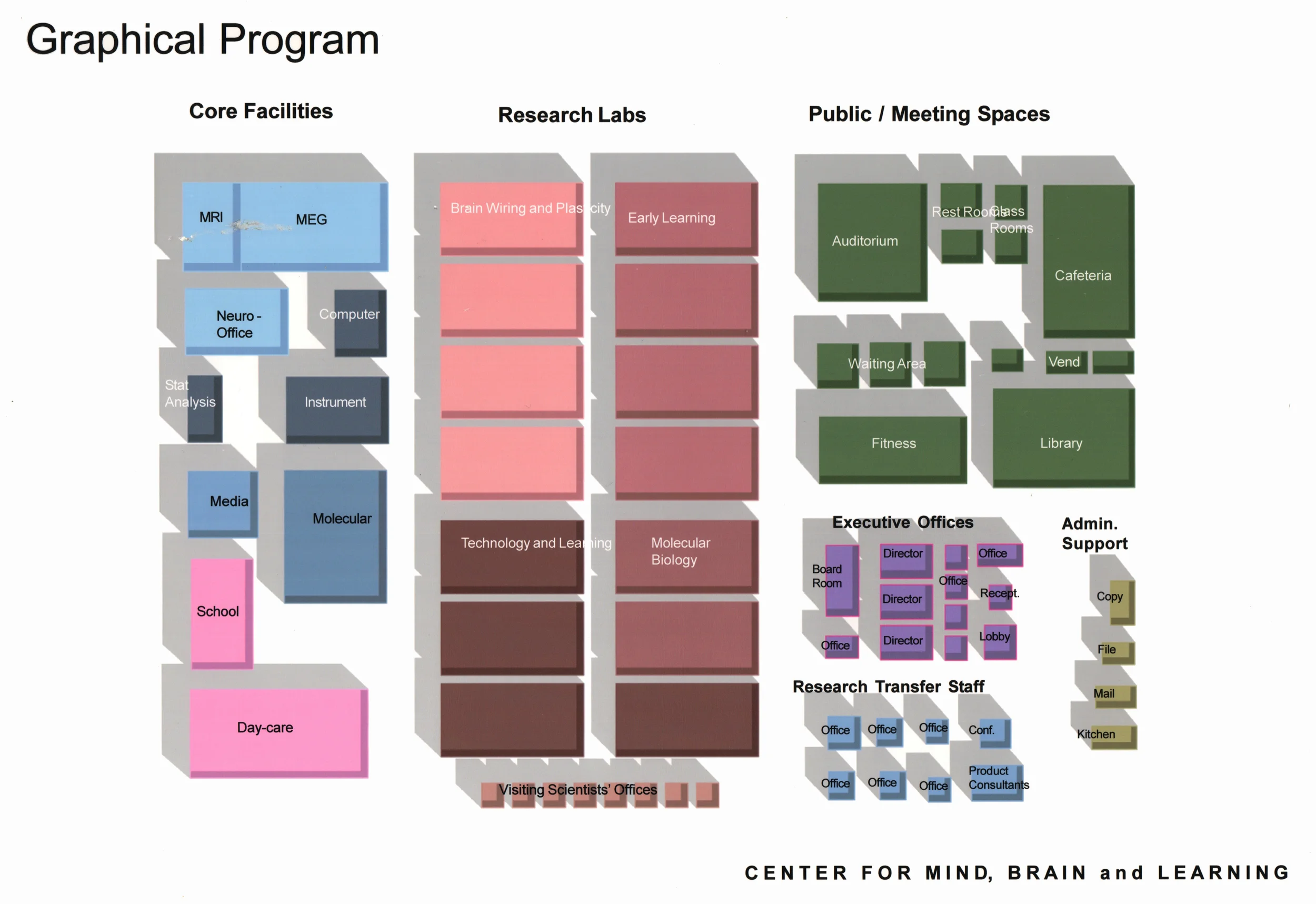
Each of these priorities can be broken down into a number of components which can be expressed and addressed by the architecture of the facility. This study begins the process of design by identifying architectural concepts of these components- The first step shall be to identify the types, size and amount of spaces required to meet the functional requirements of the Center. The second step will begin to suggest the relationships of key spaces to each other as well as the quality of the spaces involved. The final step will take the results of the first two steps and merge them into a number of alternative concepts for the Center. These concepts will be rough massing studies that will begin to suggest organization and three dimensional relationships of the spaces to each other and the potential site which at this time is undetermined.
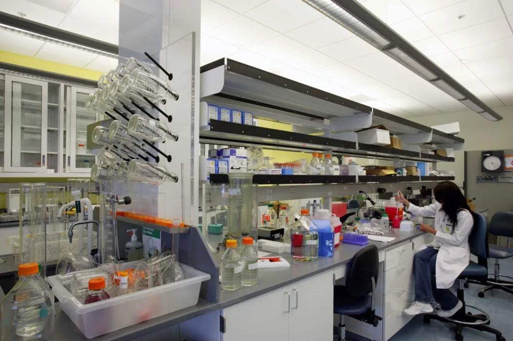
These will be wet labs that may include disciplines such as Embryology, Neurophysiology, and Biochemistry. They will require typical services (gas, air, vacuum, cold and pure water), fumehoods, biosafety cabinets, wet benches, sinks, and equipment such as centrifuges, freezers, incubators, and shakers. These labs should be adjacent to the Molecular Core facility described below.


The disciplines associated with the early learning laboratories may include Developmental Neurobiology, Educational Psychology, Speech and Hearing Sciences, and Linguistics. Their emphasis will be on human subjects with a focus on behavior and psychological experiments. The labs will include testing rooms (some of which require sound control), experiment control rooms, and patient waiting areas. Some of the testing rooms will require radio frequency sheilding.

The disciplines of Computer Science and Engineering, Bioengineering and Electrical Engineering make up the Technology and Learning Laboratories. These are dry labs that involve work primarily with electronics and large instruments which require few piped services, very little bench space, and flexible open space. Because of the sensitive electrical equipment in these labs environmental control is critical including temperature, humidity and vibration control, and clean power.

The disciplines that make up this type of laboratory may include Neurobiology, Neurological Surgery, Psychiatry, and Radiology. Of all the departments these labs will vary the most with characteristics of all the types of labs mentioned above.

The analysis of the data generated by the neuroscience core is accomplished in this core facility. It is comprised mainly of individual offices and some open office space. The equipment needs focus on the computers required to do the imaging and data analysis.

This core would be adjacent to the Molecular Biology research laboratories. It would contain the lab support spaces such as tissue culture (including a BL3 tissue culture room), radioisotope room, chemical storage, an autoclave room, glass wash room, constant temperature room, and darkroom. It would also contain a number of large equipment and storage rooms.
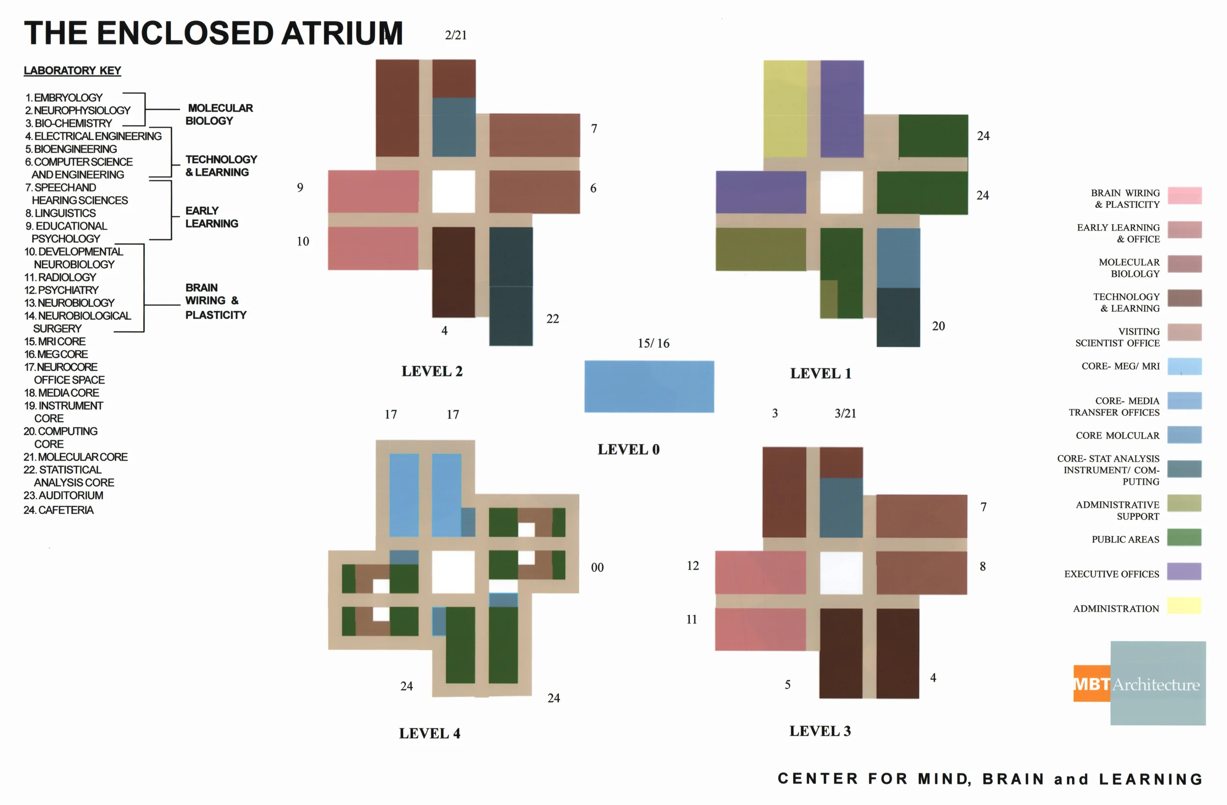
The enclosed atrium scheme creates an environment that identifies the various types of research groups while maximizing contact between the investigators. Each wing is designed to the specifications of the research discipline. Interdisciplinary research is enhanced by the ability for casual interactions between investigators from different research groups. This is accomplished by minimizing the travel distances between the different disciplines, locating research cores at the intersection of the research groups, and locating all offices together. An interactive stair concentrates vertical circulation to the atrium, connects all discipline to each other, and brings natural light to the interior core. Destination spaces used by all the disciplines and the public are located on the ground floor while other destination spaces are located on the fourth floor. This maintains privacy where required and encourages interaction and circulation within the building.
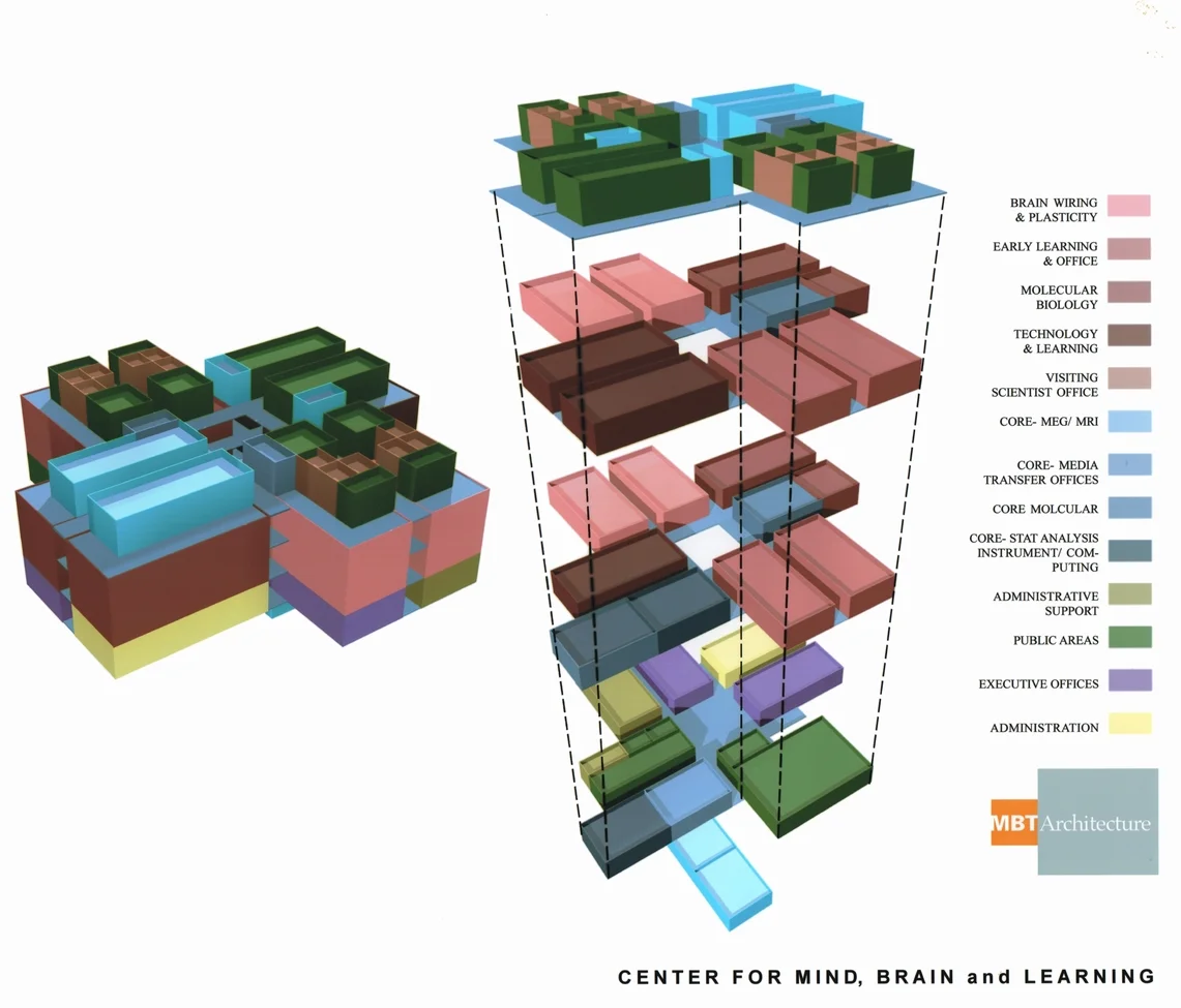
An atrium concept is typically a multi-story enclosed common space, with daylight and outside awareness. It functions like a larger "living room" for a multi-story collection of functions. This model works naturally for an urban site - like Pacific Place in downtown Seattle. It also works well in our Northest climate, bringing functions and people into closer communication. An Atrium which exceeds 3 stories wili have special costs for exhaust systems as required by code. Even at 3 stories, though, it is a viable concept for common space for this project.
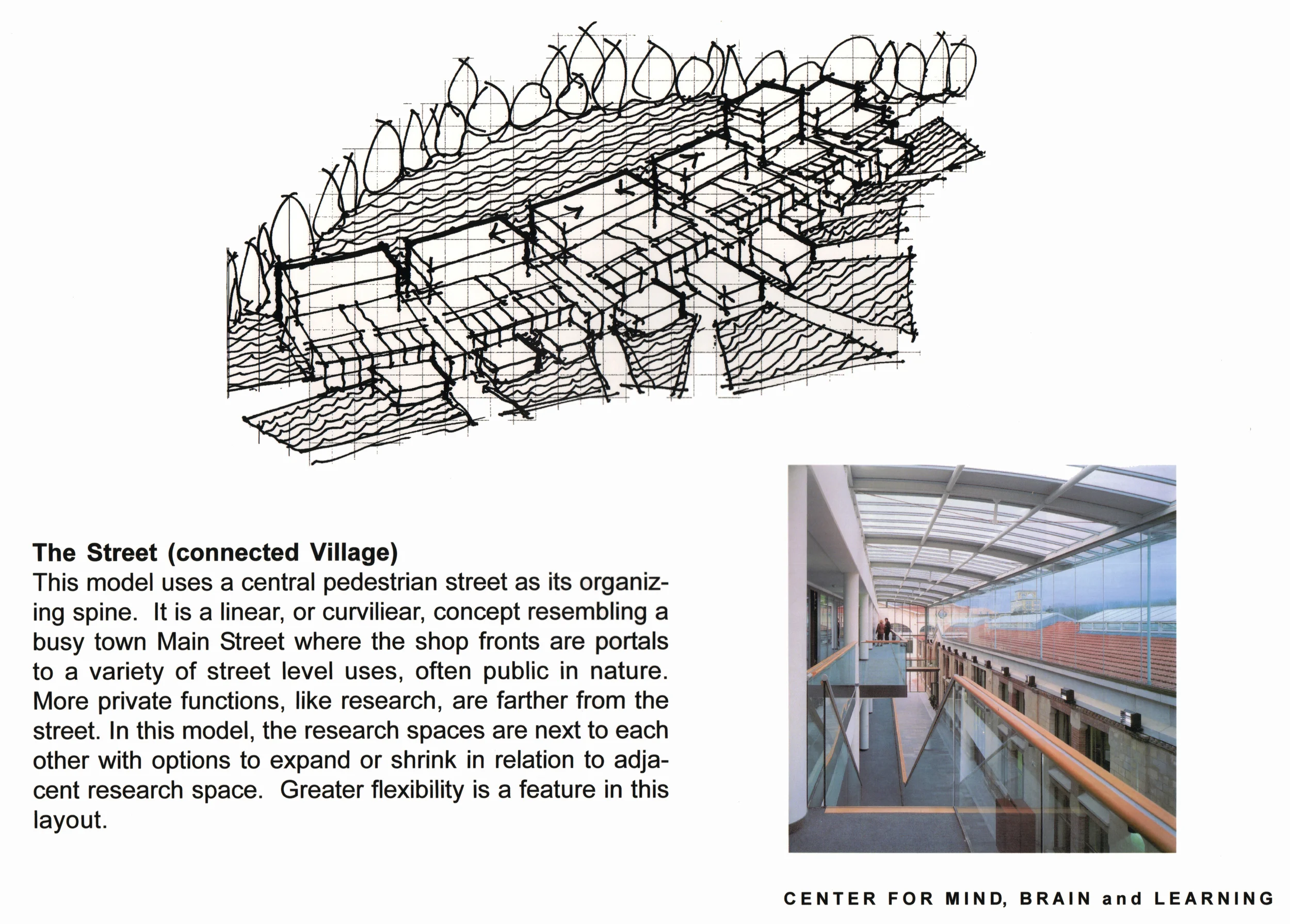
This model uses a central pedestrian street as its organizing spine. It is a linear, or curviliear, concept resembling a busy town Main Street where the shop fronts are portals to a variety of street level uses, often public in nature. More private functions, like research, are farther from the street. In this model, the research spaces are next to each other with options to expand or shrink in relation to adjacent research space. Greater flexibility is a feature in this layout.

The Street (connected Village) This model uses a central pedestrian street as its organizing spine. It is a linear, or curviliear, concept resembling a busy town Main Street where the shop fronts are portals to a variety of street level uses, often public in nature. More private functions, like research, are farther from the street. In this model, the research spaces are next to each other with options to expand or shrink in relation to adjacent research space. Greater flexibility is a feature in this layout.
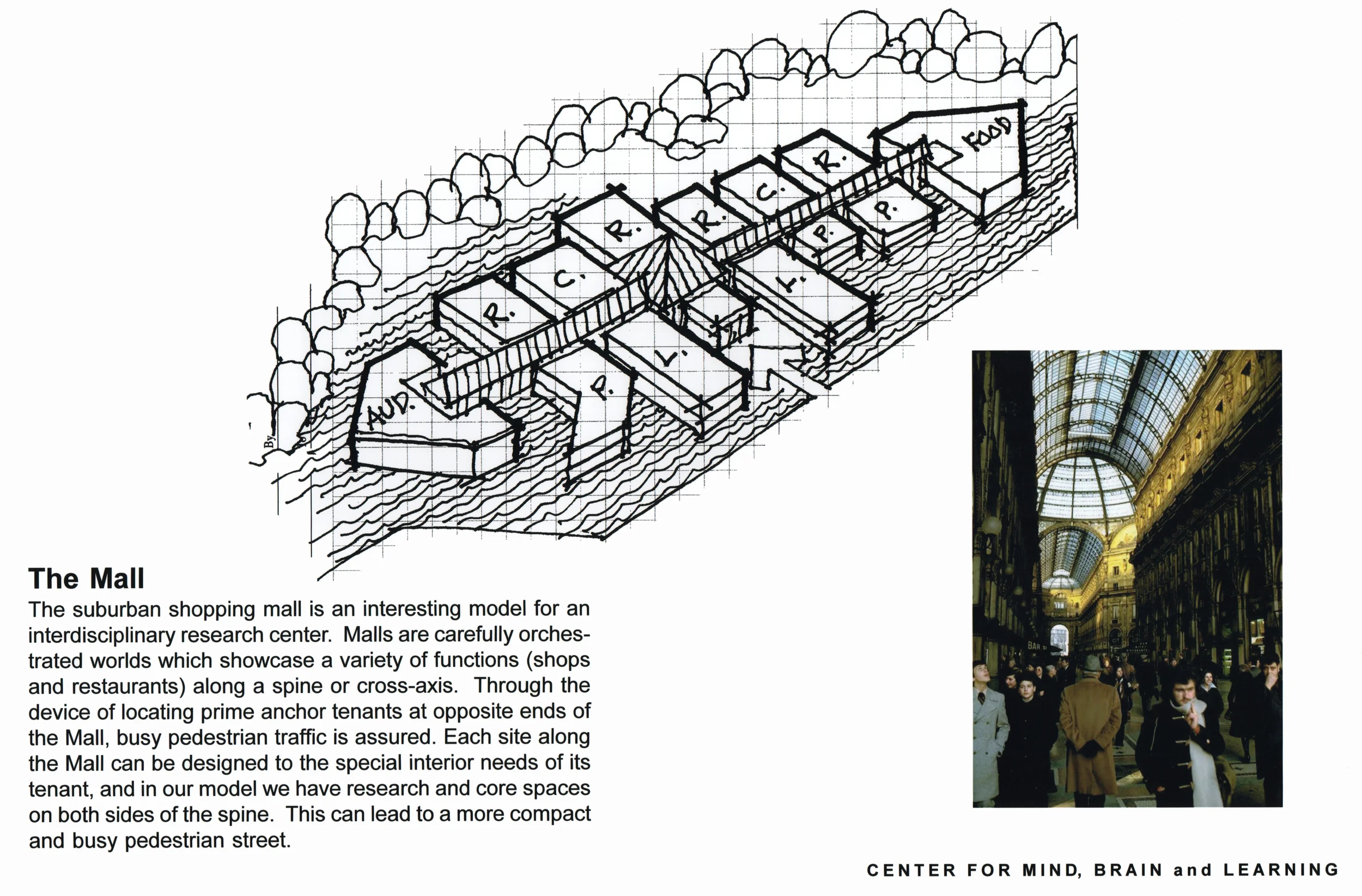

The public play areas, classrooms, executive offices and administrative spaces occur inside the main public circulation space and form an "accessible edge" to one side. Discipline cores and interaction spaces are on the other side of this long space. Research Labs on second and third levels partly overlap discipline cores for vertical penetration and circulation. They also over-sail lower level recurring mechanical spaces and allow gaps between labs for light penetration and views out of the main public space into the landscape. The structural strategy is clear, variable bay sizing is possible and mechanical specificity and flexibility is achievable. The main entrance is defined by the auditorium and the cafeteria, forming the major interaction space. Smaller, incidental interaction spaces occur at the gap between research buildings which are secondary secure entrances to each discipline off of the internal street formed by public programs and discipline cores. The intended result is that cross-fertilization occur within the central circulation fostered by interaction spaces at each secondary entrance which is shared between discipline cores. The shallow building depth brings high visibility to all ground level spaces and allows the project to have "expandability by department".
Pros: Low Rise, Structural strategy is clear, Variable bay sizing is possible, Mechanical specificity is achievable, Mechanically flexible, Secure entrances are shared between discipline cores, Shallow building depth brings high visibility to all ground level spaces, Expandability by department, Clear security zones
Cons: Long Travel Distances, Maximum Roof Area, Maximum Foundations & Groundwork, Maximum Exterior Wall, Larger Site Coverage, Drainage Issues

The suburban shopping mall is an interesting model for an interdisciplinary research center. Malls are carefully orchestrated worlds which showcase a variety of functions (shops and restaurants) along a spine or cross-axis. Through the device of locating prime anchor tenants at opposite ends of the Mall, busy pedestrian traffic is assured. Each site along the Mall can be designed to the special interior needs of its tenant, and in our model we have research and core spaces on both sides of the spine. This can lead to a more compact and busy pedestrian street.

In this model, each major group occupies a separate building, with separate identity and character appropriate to its needs. Common space and shared space is created at ground level in a series of Village spaces - buildings corridors and courtyards through which everyone would walk to meet and confer.

Placing equal emphasis at both ends of a linear progression of public spaces, the Cafeteria and the Auditorium are connected by discipline cores and low-rise research spaces. On one side, heavily serviced research buildings such as Neuro-Science, Molecular Biology and Bioengineering, engage the spine and are separated by natural light shafts. These research intensive buildings are immediately opposed by less technically loaded buildings which engage the spine at angles in order to create a sequence of triangular public interaction spaces along the length of the circulation spine.
Pros: Low Rise Structure Natural light Penetration, Clear separation of buildings types, Visible media and business apparatus, Clear security zones, Clear mechanical strategy, Clear structural strategy
Cons: Long Travel Distances, Maximum Roof Area, Maximum Foundations, Maximum Exterior Wall, Larger Site Coverage, Extensive Drainage Issues
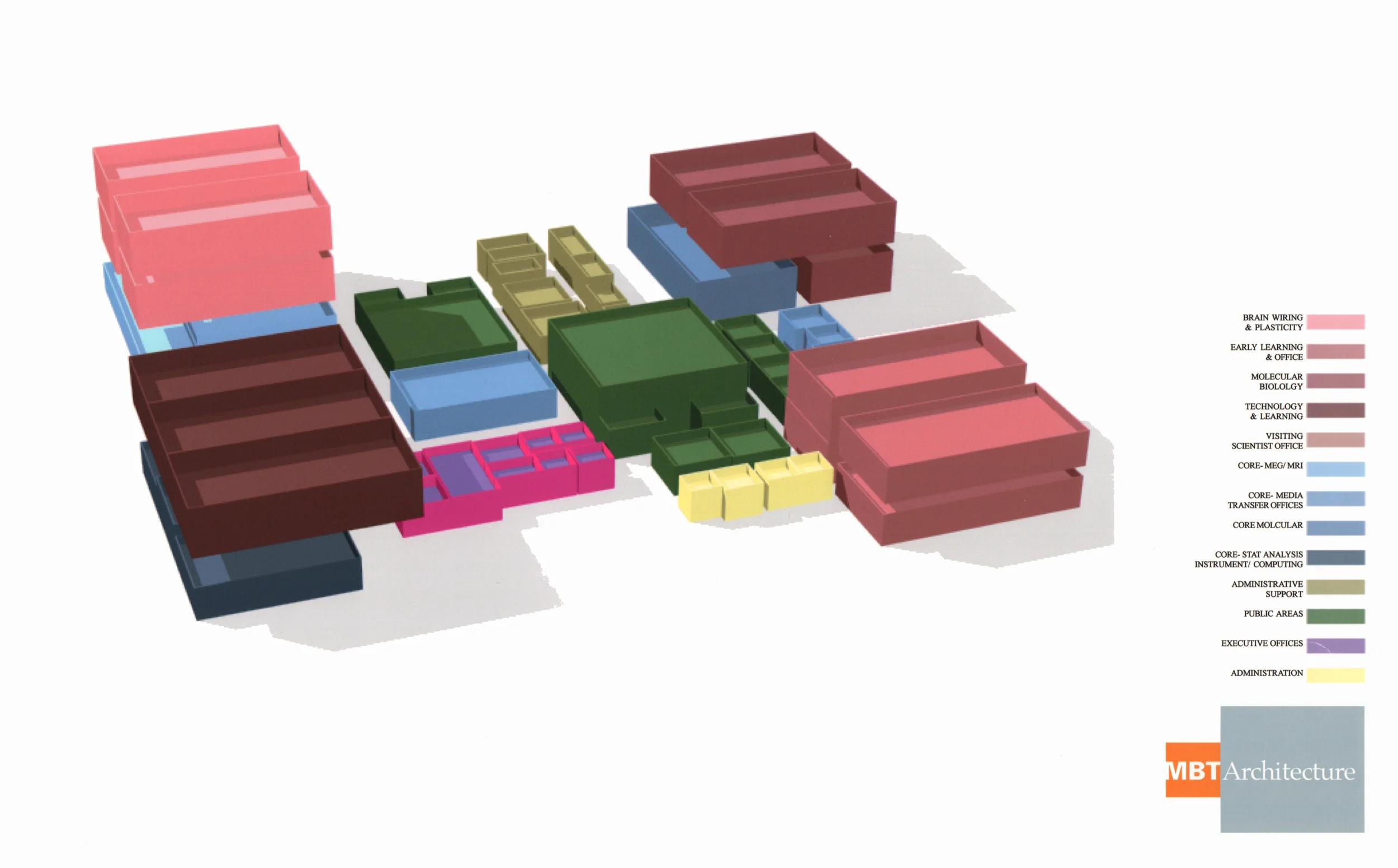
The Village In this model, each major group occupies a separate building, with separate identity and character appropriate to its needs. Common space and shared space is created at ground level in a series of Village spaces - buildings corridors and courtyards through which everyone would walk to meet and confer.
London Underground
Project Summary:
Architecture Firm: London Underground Jubilee Line Components Design Team
Client: London Underground
Date of Construction Completion: Sept. 1999
John Millard's Role: Industrial designer of componentry for Services Distribution System
Date of Design Effort Complete: Schematic Design- April 1995, Design Development- May June 1995, Construction Documentation- Sept. 1995
London Underground planned for the extension of the Jubillee Line Underground Service over several decades starting in the 1970s. The technology of tunnel boring machines had been tested with the Channel Tunnel in the 1980s and yet the geology of the London Basin represented a particular challenge to tunnel engineers due to the varying diversity of expansive clay sub-strata. In order to address each type of substrata, a variety of types of tunnel linings were designed for each condition. Segmented Concrete, Cast Iron, Precast Concrete and Cut and Cover tunnels were constructed over various segments of the Jubilee Line Extension. The interior surface of each type of tunnel lining required a different attachment method for suspending neccessary services such as lighting, communications, life safety and fire protection devices. While these attachment methods varied for each tunnel lining condition, London Underground set aside a task for a group of industrial designers known as The London Underground Jubilee Line Extension Components Team led by Roland Paoletti to design a family of components and a system of services distribution that would be interchangeable from one station to another. Additionally, these components would be be durable with a 50 year design life.
The London Underground Jubilee Line Extension Components Team was a group of approximately 12 designers whose task of delivering schedule information, safety for travelers, sufficient amounts of lighting, emergency alarms, seating, refuse receptacles, ticketing gates, variable information displays, public address speakers, closed circuit tv cameras, and a method of delivering power and communications to all of those components- was defined by a system requirements specification written by London Underground's transportation engineers and public health and safety directorate. Interpreting this document and preparing proposals for approval in order manufacture prototype components for each one of these services was a process that spawned a dialogue between departments of this organization that was cumbersome to obtain approvals. Roland Paoletti, the architect who worked with Le Corbusier was hired with the purpose of assuring that this family of components was designed on budget and on schedule, but also that these components were beautiful and aesthetically formed a family of related objects so that lights, speakers, signage, gates, benches, balustrades, etc. all looked like they belonged together in the same underground network.
The first task in defining this family of objects was to develope a standardized cable tray solution that would carry both AC and DC electricity of varying voltages, CAT V data cables, fire alarm cable, coaxial cable, fibre optic cable and telephone cable. This purpose built cable tray would be extruded with compartments that carried each of these services to their intended appliances. The delivery of power and communications was not all that this cable tray would perform, it would also act as a component hub that enabled speakers, or cameras or lights or displays to be plugged in to this cable tray that was to be suspended from the tunnel linings in the plain sight of all who travelled on the Underground. The components team would develop methods of coupling these extrusions together in such a way that opportunities to "plug in" would be created at each coupling, and the cable tray itself would be split into two "wings" that formed a gap betwixt the two wings in order to create a multi purpose component bay that continuously offered opportunities for light, sight, sound and information to be displayed. The design of this cable tray evolved beyond that descriptor and it was soon call a "Selective Services Distribution System" otherwise known as "The Boom".
The boom was going to become a ubiquitous sight within the London Underground Network of rail platforms, passenger access tunnels, escalator halls and concourses/ ticketing halls- not just on the Jubilee Line, but system wide, a solution to the growing need for cameras, public address and other safety features was needed. The components team was recognized as having produced a strong concept for The Boom by the engineers and standards inspectors who reviewed the design and so permission to manufacture prototypes of The Boom was given and work was started on the extrusion of the prototype Boom. The cost of creating a dye to produce the extrusion was mitigated by the "two wing" design, enabling the dye to be smaller- but each wing had a different cross section so there had to be two dyes made, one for each wing. Cable fill calculations were complex because The Boom was not a ventilated cable tray. It required washing periodically and so the cable fill calculation was determined to be a conduit calculation and not a ventilated cable tray. The tunnels in the London Underground are periodically thoroughly pressure washed. Electrical enclosures have to be rated for pressure washing- and so the Boom was determined to be a washable enclosure, the equivalent of somewhere between a NEMA 3R and a NEMA 4 enclosure in the USA.
Once the cable fill calculations and the access requirements to these Booms were determined, the method of transitioning from one segment or extrustion to another, through a coupling with a series of appropriately sized nipples was designed. These couplings were also one of the locations where a service opportunity could occur as described above. The location was between the wings of The Boom. The team cleverly designed what are known in England as "Halfen Channels" into the extrusion so that brackets could be designed to randomly snap and slide into any location along the Boom in order to site the lighting bracket of CCTV bracket into the desired position. These brackets were known as "component brackets" since they were dedicated to suspending brackets between the wings of the boom. The Boom Brackets were brackets that captured the ends of the extrusions and also allowed the cables to pass continuously in their nipples from one segment of Boom Wing to the next. These Boom brackets were the point of suspension of the Boom segment where aircraft rod with swaged stainless steel fittings are bolted to the bracket at one end and to the tunnel lining at the other.
The aircraft rod were extremely expensive but the quantities that were required for the London Underground were sufficiently large economic order quantities that the team was able to make a strong case for these to be purchased by the contractor who would install the SSDS. The benefit of the aircraft rod was that it was telescopic in length. This vastly reduced the complexity of the attachment method by enabling multiples of 6" rods to be ordered and the telescopic tolerance of the rod would accommodate precisely the desired length in situ. What that rod attached to depended on the type of tunnel lining as was described at the outset. Whether this attachment turned out to be a through-bolted condition or a resin-epoxy anchor shot into segmented concrete was now a definable coordination exercise and not dictating the design of the SSDS based on the type of tunnel lining or the structure that attaches to it.
The role that John Millard had on the team was to design bracketry that would be compatible with the pre-existing family of components which to date included The Boom, The Component Bracket and the Boom Brackets. Therefore the basis of design was established by these components and John Millard designed the lighting bracket, the CCTV bracket, the variable information display bracket, the speaker bracket and the signage brackets for the SSDS. These brackets were designed using 3d Studio, MicroStation and Autocad with some use of Micro-GDS.



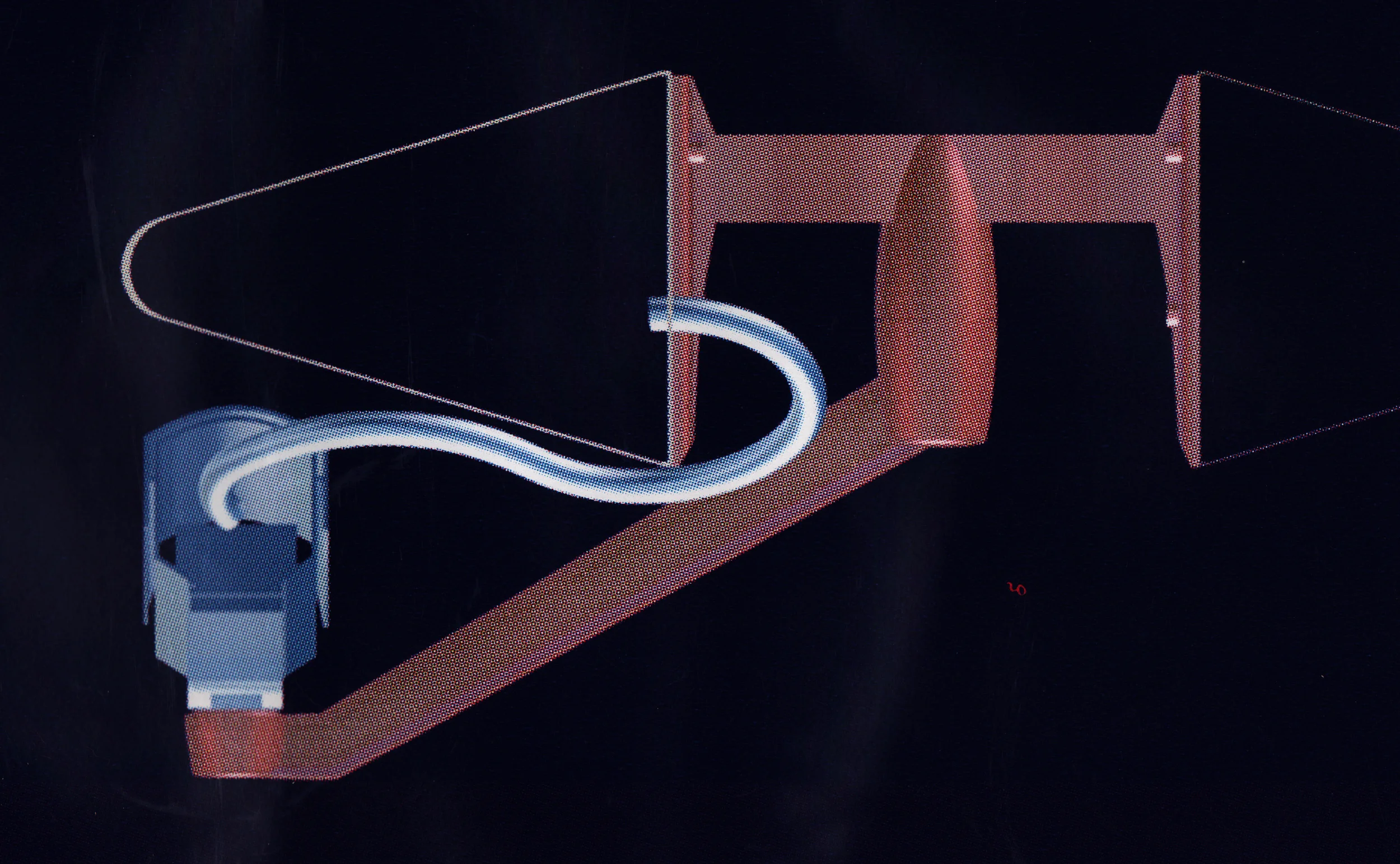

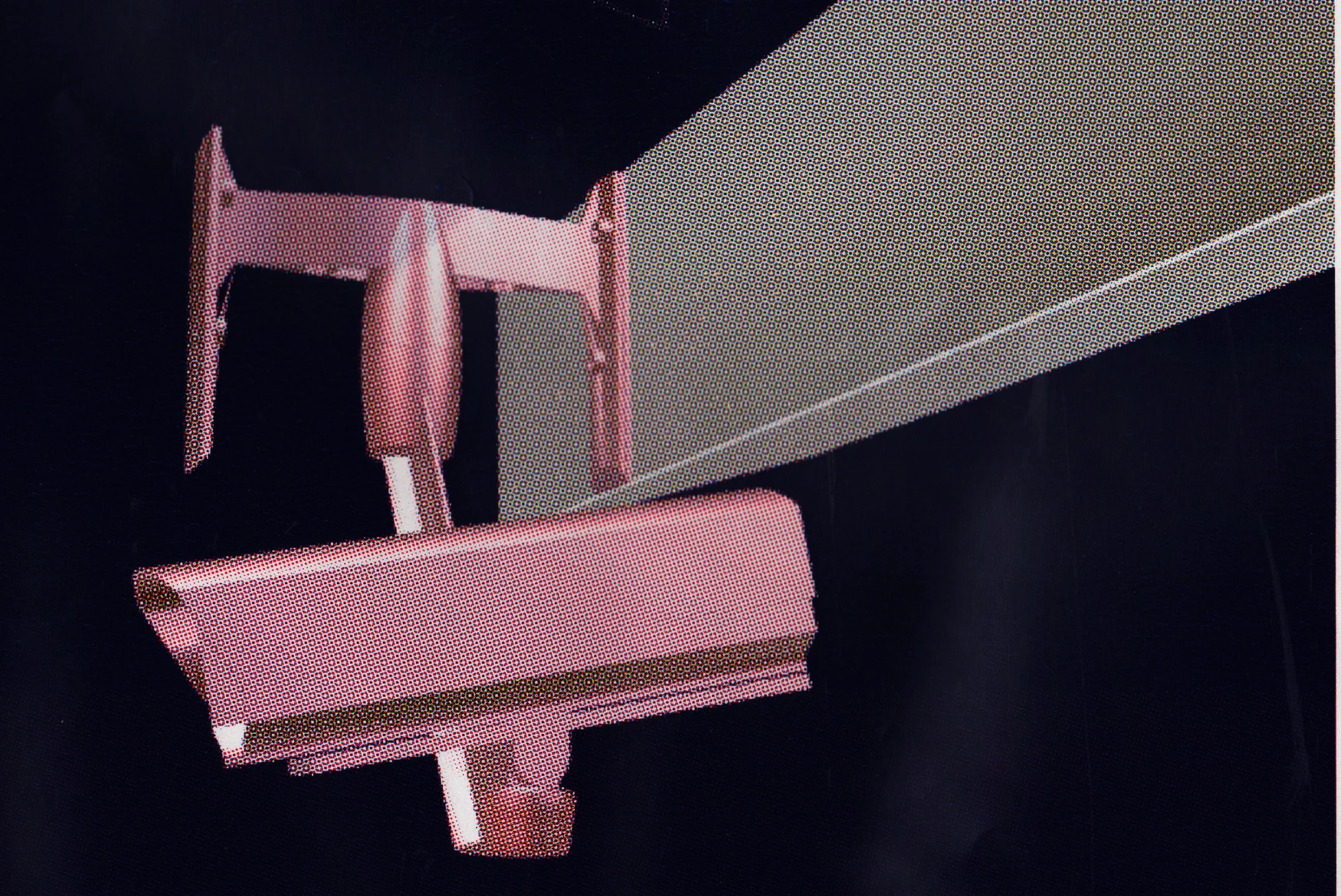
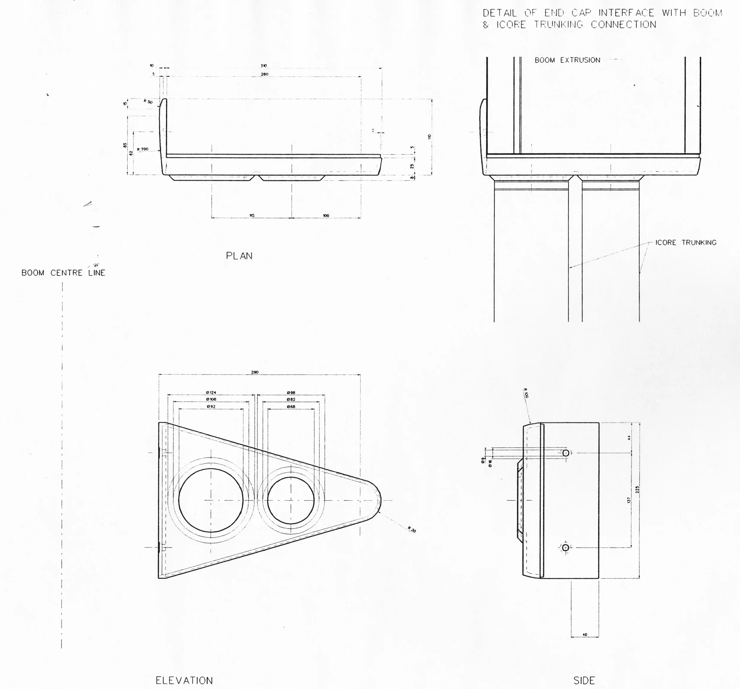





London Underground- Jubilee Line Extension Station: North Greenwich
Project Summary:
Architecture Firm: Allsop & Partners/ London Underground Jubilee Line Components Design Team
Client: London Underground
Date of Construction Completion: Oct. 2000
John Millard's Role: Component Design for Services Distribution System and Architectural Metal Balustrades
Date of Design Effort Complete: Schematic Design- April 1995, Design Development- May June 1995, Construction Documentation- Sept. 1995
London Underground planned for the extension of the Jubillee Line Underground Service over several decades starting in the 1970s. The technology of tunnel boring machines had been tested with the Channel Tunnel in the 1980s and yet the geology of the London Basin represented a particular challenge to tunnel engineers due to the varying diversity of expansive clay sub-strata. In order to address each type of substrata, a variety of types of tunnel linings were designed for each condition. Segmented Concrete, Cast Iron, Precast Concrete and Cut and Cover tunnels were constructed over various segments of the Jubilee Line Extension. The interior surface of each type of tunnel lining required a different attachment method for suspending neccessary services such as lighting, communications, life safety and fire protection devices. While these attachment methods varied for each tunnel lining condition, London Underground set aside a task for a group of industrial designers known as The London Underground Jubilee Line Extension Components Team led by Roland Paoletti to design a family of components and a system of services distribution that would be interchangeable from one station to another. Additionally, these components would be be durable with a 50 year design life.
The London Underground Jubilee Line Extension Components Team was a group of approximately 12 designers whose task of delivering schedule information, safety for travelers, sufficient amounts of lighting, emergency alarms, seating, refuse receptacles, ticketing gates, variable information displays, public address speakers, closed circuit tv cameras, and a method of delivering power and communications to all of those components- was defined by a system requirements specification written by London Underground's transportation engineers and public health and safety directorate. Interpreting this document and preparing proposals for approval in order manufacture prototype components for each one of these services was a process that spawned a dialogue between departments of this organization that was cumbersome to obtain approvals. Roland Paoletti, the architect who worked with Le Corbusier was hired with the purpose of assuring that this family of components was designed on budget and on schedule, but also that these components were beautiful and aesthetically formed a family of related objects so that lights, speakers, signage, gates, benches, balustrades, etc. all looked like they belonged together in the same underground network.
The first task in defining this family of objects was to develope a standardized cable tray solution that would carry both AC and DC electricity of varying voltages, CAT V data cables, fire alarm cable, coaxial cable, fibre optic cable and telephone cable. This purpose built cable tray would be extruded with compartments that carried each of these services to their intended appliances. The delivery of power and communications was not all that this cable tray would perform, it would also act as a component hub that enabled speakers, or cameras or lights or displays to be plugged in to this cable tray that was to be suspended from the tunnel linings in the plain sight of all who travelled on the Underground. The components team would develop methods of coupling these extrusions together in such a way that opportunities to "plug in" would be created at each coupling, and the cable tray itself would be split into two "wings" that formed a gap betwixt the two wings in order to create a multi purpose component bay that continuously offered opportunities for light, sight, sound and information to be displayed. The design of this cable tray evolved beyond that descriptor and it was soon call a "Selective Services Distribution System" otherwise known as "The Boom".
The boom was going to become a ubiquitous sight within the London Underground Network of rail platforms, passenger access tunnels, escalator halls and concourses/ ticketing halls- not just on the Jubilee Line, but system wide, a solution to the growing need for cameras, public address and other safety features was needed. The components team was recognized as having produced a strong concept for The Boom by the engineers and standards inspectors who reviewed the design and so permission to manufacture prototypes of The Boom was given and work was started on the extrusion of the prototype Boom. The cost of creating a dye to produce the extrusion was mitigated by the "two wing" design, enabling the dye to be smaller- but each wing had a different cross section so there had to be two dyes made, one for each wing. Cable fill calculations were complex because The Boom was not a ventilated cable tray. It required washing periodically and so the cable fill calculation was determined to be a conduit calculation and not a ventilated cable tray. The tunnels in the London Underground are periodically thoroughly pressure washed. Electrical enclosures have to be rated for pressure washing- and so the Boom was determined to be a washable enclosure, the equivalent of somewhere between a NEMA 3R and a NEMA 4 enclosure in the USA.
Once the cable fill calculations and the access requirements to these Booms were determined, the method of transitioning from one segment or extrustion to another, through a coupling with a series of appropriately sized nipples was designed. These couplings were also one of the locations where a service opportunity could occur as described above. The location was between the wings of The Boom. The team cleverly designed what are known in England as "Halfen Channels" into the extrusion so that brackets could be designed to randomly snap and slide into any location along the Boom in order to site the lighting bracket of CCTV bracket into the desired position. These brackets were known as "component brackets" since they were dedicated to suspending brackets between the wings of the boom. The Boom Brackets were brackets that captured the ends of the extrusions and also allowed the cables to pass continuously in their nipples from one segment of Boom Wing to the next. These Boom brackets were the point of suspension of the Boom segment where aircraft rod with swaged stainless steel fittings are bolted to the bracket at one end and to the tunnel lining at the other.
The aircraft rod were extremely expensive but the quantities that were required for the London Underground were sufficiently large economic order quantities that the team was able to make a strong case for these to be purchased by the contractor who would install the SSDS. The benefit of the aircraft rod was that it was telescopic in length. This vastly reduced the complexity of the attachment method by enabling multiples of 6" rods to be ordered and the telescopic tolerance of the rod would accommodate precisely the desired length in situ. What that rod attached to depended on the type of tunnel lining as was described at the outset. Whether this attachment turned out to be a through-bolted condition or a resin-epoxy anchor shot into segmented concrete was now a definable coordination exercise and not dictating the design of the SSDS based on the type of tunnel lining or the structure that attaches to it.
The role that John Millard had on the team was to design bracketry that would be compatible with the pre-existing family of components which to date included The Boom, The Component Bracket and the Boom Brackets. Therefore the basis of design was established by these components and John Millard designed the lighting bracket, the CCTV bracket, the variable information display bracket, the speaker bracket and the signage brackets for the SSDS. These brackets were designed using 3d Studio, MicroStation and Autocad with some use of Micro-GDS.

Photo taken in Nov. 2019 by John Millard shows smoke hood designed to evacuate smoke from burning train. Hood also transports selective services for distribution along the entire station. CCTV, Variable Information Display, Public Audio, Power, Communications and Fire Fighting Appliances are baked in. Design by Will Alsop. JBM designed glass balustrade bracketry details for this station. Which was fun.
The Mezzanine Piers shared footings that were expensive steel reinforced concrete islands in the London Clay. The ceramic casings are driven from clay. London Underground has a long heritage of ceramic wall and floor coverings in station design.
The Speaker Bracket is similar to the other brackets in the twelve other stations, Based on a lost wax casting of a t-flange, it it a family of t-flanges that support the various devices that populate the Jubilee Line Extension.
London Underground has for over one hundred years provided platforms to its stations that compare with most of the world’s subway stations in that they have required the pedestrians to stand away from the edge of the platform prior to accessing the train. The Jubilee Line Platforms are the first in London to provide fall protection for pedestrians.
London Underground has for over one hundred years provided platforms to its stations that compare with most of the world’s subway stations in that they have required the pedestrians to stand away from the edge of the platform prior to accessing the train. The Jubilee Line Platforms are the first in London to provide fall protection for pedestrians.

In addition to the extensive escalators in Greenwich Station, the design also called for egress stairs from the platform to the mezzanine above where pedestrians can make their way to the surface from this cut and cover station that lies approximately 30 meters beneath grade.
The original design for the balustrade was a lost wax casting design but the value engineered version that was constructed was a stainless steel fabrication that approximated the the original design.

Conceptual animation showing components designed by John Millard using freehand sketching and 3d Studio R3 by Autodesk in 1995.

The constructed balustrade has supports that cantilever off of the mezzanine and lean out over the void. The Blue Glass backdrop of the 30m retaining walls recede into the background where escalators unite the levels with diving forms of stainless steel and fluid movement of people.
The lead designer of the North Greenwich Station was Will Allsop, the Pritzker Prize winning architect that followed through all of his buildings with a characteristic art. The buildings he designed are invested with curiosity and care that drills down into the smallest details and direction that materials lead the eye with.
The edge of the Mezzanine oversails the platforms 30m below. In order to defend against debris from falling from the mezzanine, a footrail detail that provides for an embedment to anchor the balustrade post into the concrete is hidden by a continuous stainless steel cover.

Here in this photo, the final constructed detail showing the handrail as a hybrid assembly of cast alloy with stainless steel plate, sandwiched together in an assembly of components that form a strong connection to the welded flange of the off-vertical post.
The glass balustrade can be seen cantilevering over the platform from the Mezzanine above. Allsop & Partners designed the station in 1993 and incorporated the twin canted columns characteristic of their work.

The forest of splayed, sloping columns that support the surface of the street above carry the mezzanine of the station superstructure. This promenade of people carries them to the final flight up to the street.
Point White Drive Plans
After completing the Diploma of Architecture at the Architectural Association School of Architecture in July 1993 my wife and I traveled to Bainbridge Island for a one-month house-swap. The island is off the coast of Seattle and is accessible by ferry from downtown. There are numerous architecture firms in Seattle and this opportunity to visit the Pacific Northwest came with several job interviews. The economy in the early 1990s was depressed and there was high unemployment among architects. We returned to London to work for another two years. It was during this two year period that I completed the design and construction of a Functional Brain Imaging Laboratory for the Welcome Trust in Queens Square, London for the Royal Institute of Neurology while employed by the Devereux Partnership. In 1995 I completed my RIBA part three examination and made plans to relocate to Bainbridge Island. We initially looked at existing homes to purchase for our family. We found a 3 acre piece of land on the south end of Bainbridge Island that had magnificent views of Rich Passage, part of the Puget Sound that comprises the body of water off of the south end of Bainbridge Island.
Drilling for Water- a first step
The prospect of designing and building our own home came with a great deal of responsibility and risk for the development of the land. Since there is no utility water supply to many locations on Bainbridge Island it was necessary to drill a water well. In order to purchase the land, the feasibility of striking water had to be explored prior to making a offer on the land. Hence, a well drilling rig required access to the low point on the land which meant that we had to cut some trees and perform some initial clearing. The clearing of trees required us to obtain a clearing permit. We had the permission of the land owner to clear a limited number of trees in order to drill an exploratory water well. Once we struck water we determined that there was more than adequate water pressure to supply our house as well as one or two other houses. The water we found was also clear of any calcium deposits or other contaminants that can often require domestic water to be treated on-site.
After having accepted our offer for the land, the owners gave us permission to carry on clearing the land of the trees that we intended to mill and to have kiln dried for our house's decking material, siding material, beams, posts, interior trim and soffit material. The logger who cut the trees required a beam schedule from me in order to determine the length of the logs that were required for our house's timber package. The design for the house had evolved sufficiently for us to provide him with the information he needed in order to start making the timber from the logs. We had originally intended to design a timber-framed home with traditional exposed beams and brackets that are common to the craftsman style of the Pacific Northwest. The less-expensive option was to balloon frame the house in conventional house construction methods and to have a limited number of exposed beams and columns with custom bracketry to complete the joinery. Therefore, all of the conventional framing material required for the "two by" construction was purchased from the lumberyard and all of the beams and columns and all of the decking, siding and soffit material was provided from our milling operation.
After clearing the land and drilling the freshwater well, the need for a septic design was next. We hired a civil engineer and a septic field designer to provide us with an application to the department of health for our house's septic plan. This was a risky undertaking because gravity fed drainfields were becoming a liability to many home owners and the town was contemplating a ban on this type of septic design. This was because the ground was quite often not permeable enough to allow for the percolation of human waste into the ground. Our septic designer added a great deal of sandy soil to the design of our septic field which was perforated pipe encased in granite gravel. Soon we had a permitted septic design for our piece of land and that concluded the contingencies that we allowed for and the purchase of our 3 acre lot was completed in December 1995.
What remained for us to do was to complete a Wildlife Survey of our land to search for any bald eagles nests or other wildlife that could impede our construction permit. A wildlife specialist was employed to come in and do a Wildlife Survey for us. This resulted in no obstacles to our building permit and we were soon able to begin interviewing contractors for our house project. At the time that I was beginning to design the house, I was employed on a $160 million prison project for the State of Washington by NBBJ. I had completed a three-dimensional framing model of the house for the purposes of quantifying my timber package. A friend of mine who was an architect at the Miller Hull company asked if I could use some help with the construction drawings. Peter Wolff became an employee of the construction contracting company that I had engaged to build my house. Peter carried out all of the construction drawings for the house during the 1996 timeframe and construction began in 1997. The Reijnen Company was the builder of the house. The size of the house as defined in my three-dimensional framing model was reduced in order to achieve a budget of approximately $300,000. Peter was able to import my three-dimensional framing model into AutoCAD and to produce the various two-dimensional sections, plans, and elevations of the house.
Designing a House while working as an Architect- Day Job / Night Job
Design and Construction of the house during this initial period while employed by NBBJ was a full time occupation. During the period of time that I was designing the house, I was also part of large team of architects designing the Stafford Creek Corrections Center in Grays Harbor, Washington. I was also briefly involved in Swedish Hospital Phase 5 Surgery in the early days of the house project. Also during this period, the contents of our home from London was shipped in a 40 foot shipping container to our rental property on Bainbridge Island. We had arrived in Seattle in September of 1995 and our newborn son turned one on October 1. Just prior to starting construction of the house in April 1997, Josephine our third child was born to us on December 30, 1996. Presented with the same opportunity, in hindsight – I'd've had less on my plate.
The design of the house was driven largely by the geography of the site and the enormous Douglas firs that paced across the property, controlling views out of the site to the south, out to the body of water that presented us with so much maritime traffic, the sound of the ferries, the naval ships and the sounds of the sea lions in the water calling out below. The presence of and the movement of ships past our house was calling for the nautical architecture that I embraced so wholeheartedly with the south elevation of the house. The views out of the site and the southerly aspect of the property were what steered me towards the large expanses of glass. The large rectangular forms that bulge briefly through the curving wall of the south elevation created an animated interactive space that brought the outdoors in and the indoors out. During the summer, the curving deck, which wrapped around the major living spaces was a space which was next to the large plates of laminated glass that separated us from the interior of the house and frequently created an interesting hybrid space that blurred the lines between the two.
Many of the components of the house were owner provided. As discussed previously, all of the decking, siding, interior trim, soffit material, beams and posts for the house were owner provided. In addition to that, all door hardware, appliances, electrical fixtures, and balustrades were owner provided to the contractor. The deck was constructed of custom milled cedar decking which dimensionally had to be able to be bent to match the radius of the curve of the South Wall. This resulted in 3 inch wide decking material. All of the floorboards of the deck workbench in order to follow the bending cedar siding of the vertical surface. The handrail on the balustrade also had to curve with the south elevation. This material was bolted to custom stanchions that were hot dipped and lag bolted to a curving 2" x 12" facia board that terminated the 2" x 8" joist ends of the deck. In order to stabilize the curving balustrade, outriggers which hold the balustrade outwards to compensate for the inward force of the tensioned aircraft cable were attached to periodic cantilevering joists.
Another owner provided item was the detention pond which collected all of the storm water off of the driveway and all of the storm water off of the roofs. The detention pond was located to the east of the house and was frequently filled with water in the Pacific Northwest climate that measured rainfall in feet not inches. There was an excessive amount of organic debris that was blown off of the Douglass firs that collected on the roofs and would normally clog gutters but for the gutter-less design of our storm water system. All of the roofs were standing seam metal Galv-alum roofs. The Douglas Fir leaves which collected on the roof were washed down hill across the cascading slopes of standing seam metal. A French drain surrounded the house and egressed water into the detention pond through under ground pipes. The French drain was entirely constructed from Granite drain rock. This granite drain rock apron which surrounded the house created a 12 foot surface transition from green grass to granite rock. The organic debris from the roofs was easily collected at ground level periodically while the water continued on to deposit in the detention pond.
Points White is a peninsula on Bainbridge Island that has a strong southerly aspect, with views of Port Orchard Bay. The ground rises abruptly out of the passage to a height of 100 feet above sea level where the house is located. There is a significant amount of marine traffic that passes through Point White on an hourly basis.
Access to the homesite is up a very steep driveway that is a right-of-way. There are strong views of the home site from this right away. Views out of the site from a height of 100 feet above sea level are able to see ferry and naval traffic including the occasional aircraft carrier.
3169 Point White Drive is a 3 acre site that consisted of extensive Douglas Fur and Western Red Cedar trees. There was a very large western red cedar tree directly on the homesite which was milled for all of the siding, decking and soffit material for the house. The house uses a gravity-fed septic design that enabled the front yard of the house to be clear of any appurtenances in accordance with the view covenant with the next-door neighbors. Additionally, not shown on this plan is the avenue of Douglas for trees that pace across the site from the west to the east. These trees which were limbed up to a height of 50 feet controled views out of the site from the house.
The ground floor of the house has its own entrance under a covered soffit that is accessible from the carport. The gas boiler, well-controlled and electrical panel are accessible from the carport but hermetically sealed from the occupied spaces of the ground floor.
It is on the ground floor where the perfect curve of the south elevation is plotted using a cantilevering floor joists are cut along the curve using a snap line. These joists are held down to the concrete foundations using seismic holddowns specified by a structural engineer.
The semi public spaces of the ground floor are comprised of two separate building volumes each pointing out into the landscape in a different direction through the curve of the south wall. These two spaces create very large bay windows in the south wall. The windows are toughened, laminated glass.
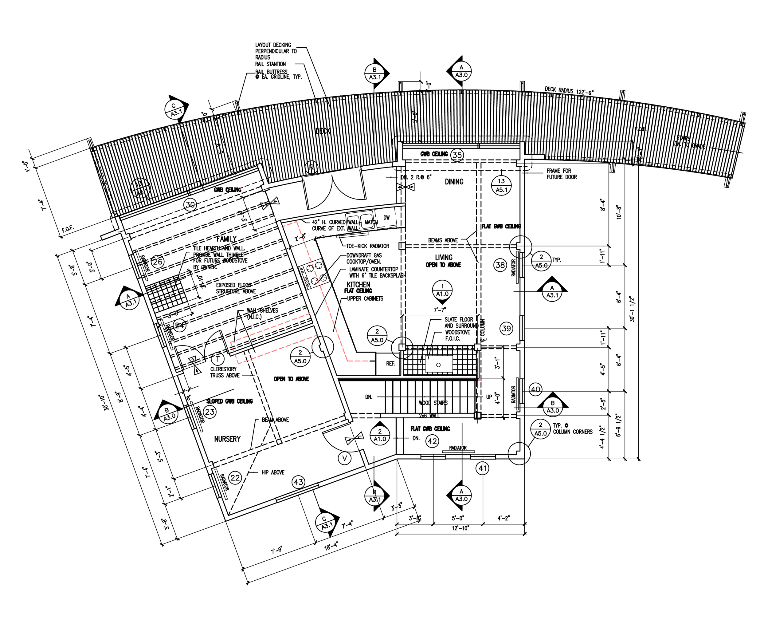
The second floor is broken into two separate levels, that step occurs around the kitchen shape. As a result of this step, the living spaces of the house, follow the natural slope of the site.
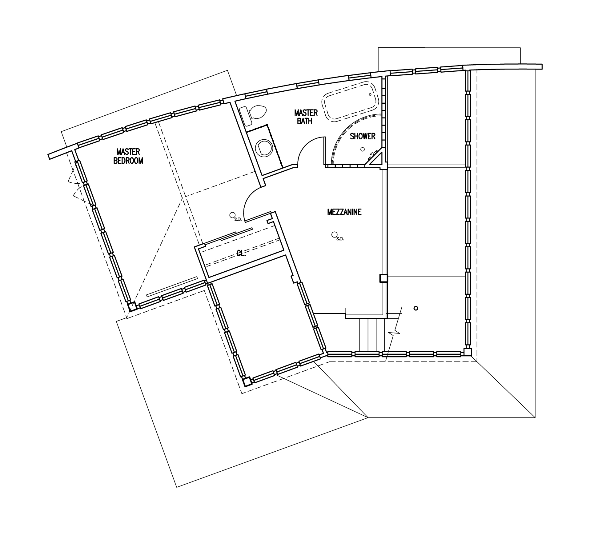
The master bedroom suite is located on the third floor. It is surrounded by sixty-five 12" x 12" clerestory windows. Some of these windows are operable and they allow warm air to escape from the high volumes of this space during the summertime. They provide a high degree of natural light in the house year round. The house complies with energy code for glazing-to-opaque wall surface ratio of 30%.
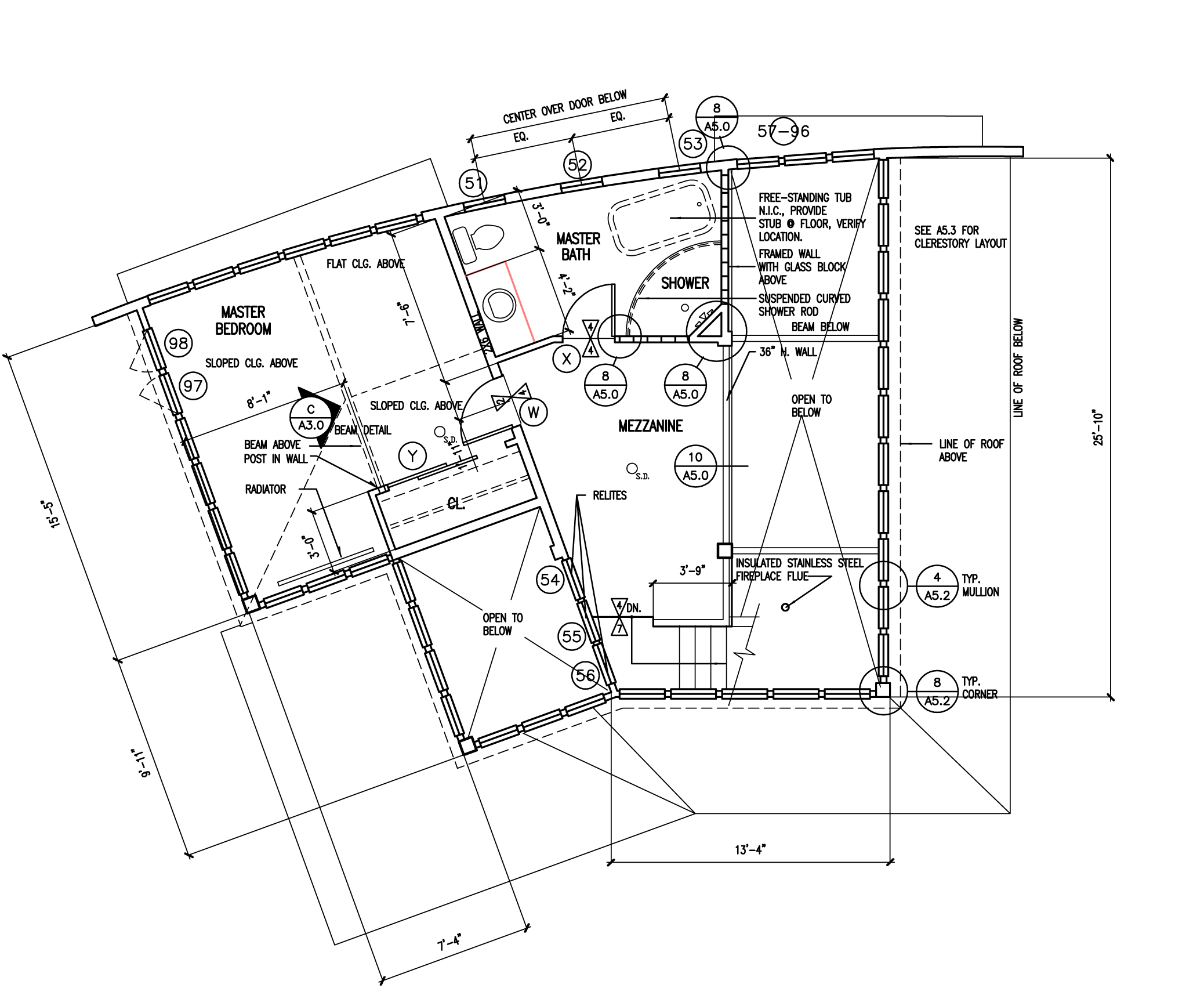
Framing of the third floor master bedroom suite required some exposed beams and some strong lintels to carry the load of the roof above the clerestory windows. Each clerestory window is separated by a pair of continuous 2"x 6" wall studs that continue from the floor plate through to the top of the wall
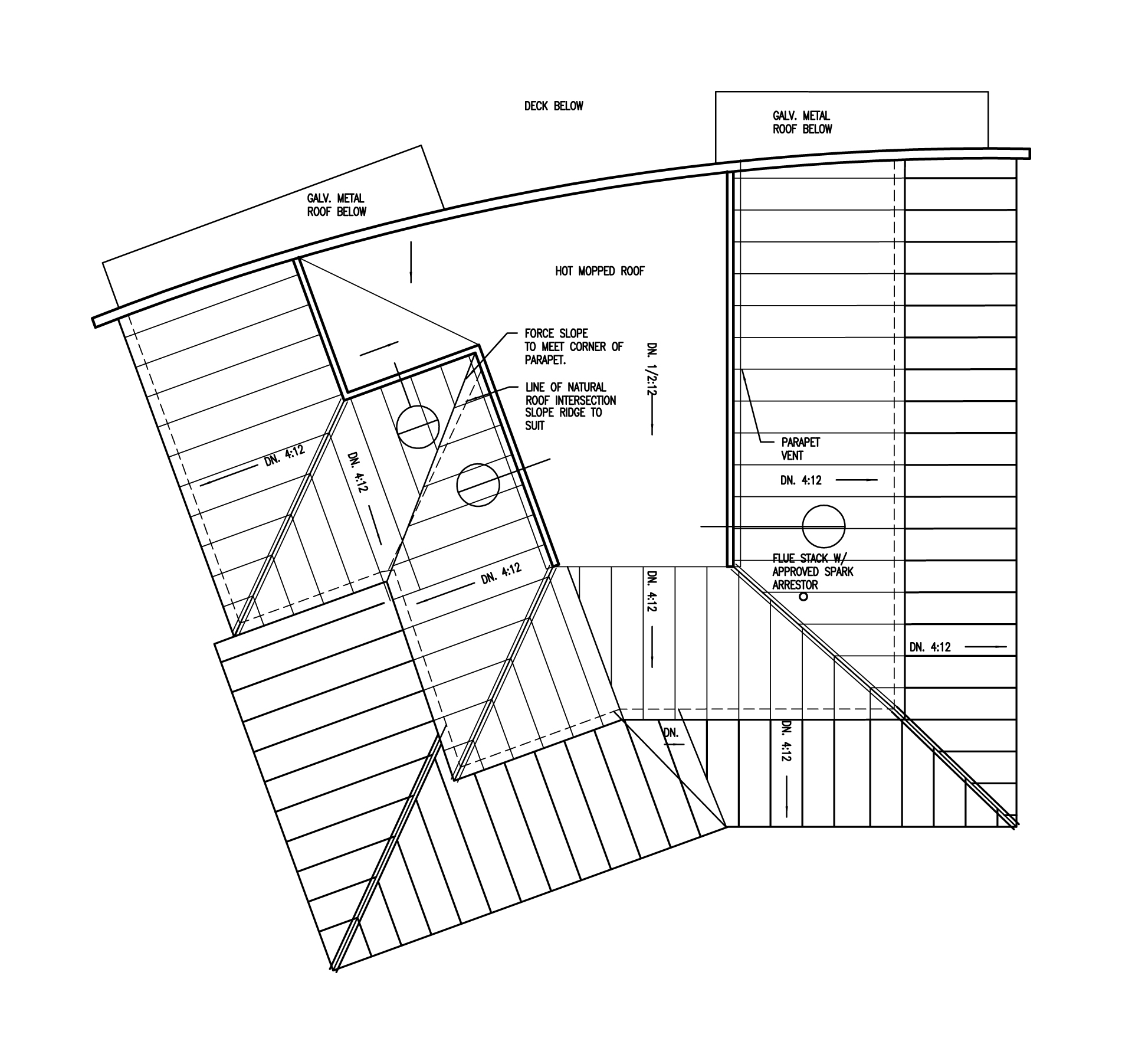
The climate in the Pacific Northwest measures rainfall feet and the wind on this end of the island takes the full brunt of the prevailing winds from the south. The foliage that blows off of the Douglas Furner trees is a significant accumulation of organic material on the roof. For this reason there are no gutters in the rainwater design for the house. The concrete foundations of the house are backfilled with soil that allows for a French drain. The drain is lined and egresses water into a detention pond on the east side of the house. The wind-driven organic matter from the trees accumulates on the ground where it is driven by the rain water off of the standing seam metal roofs.
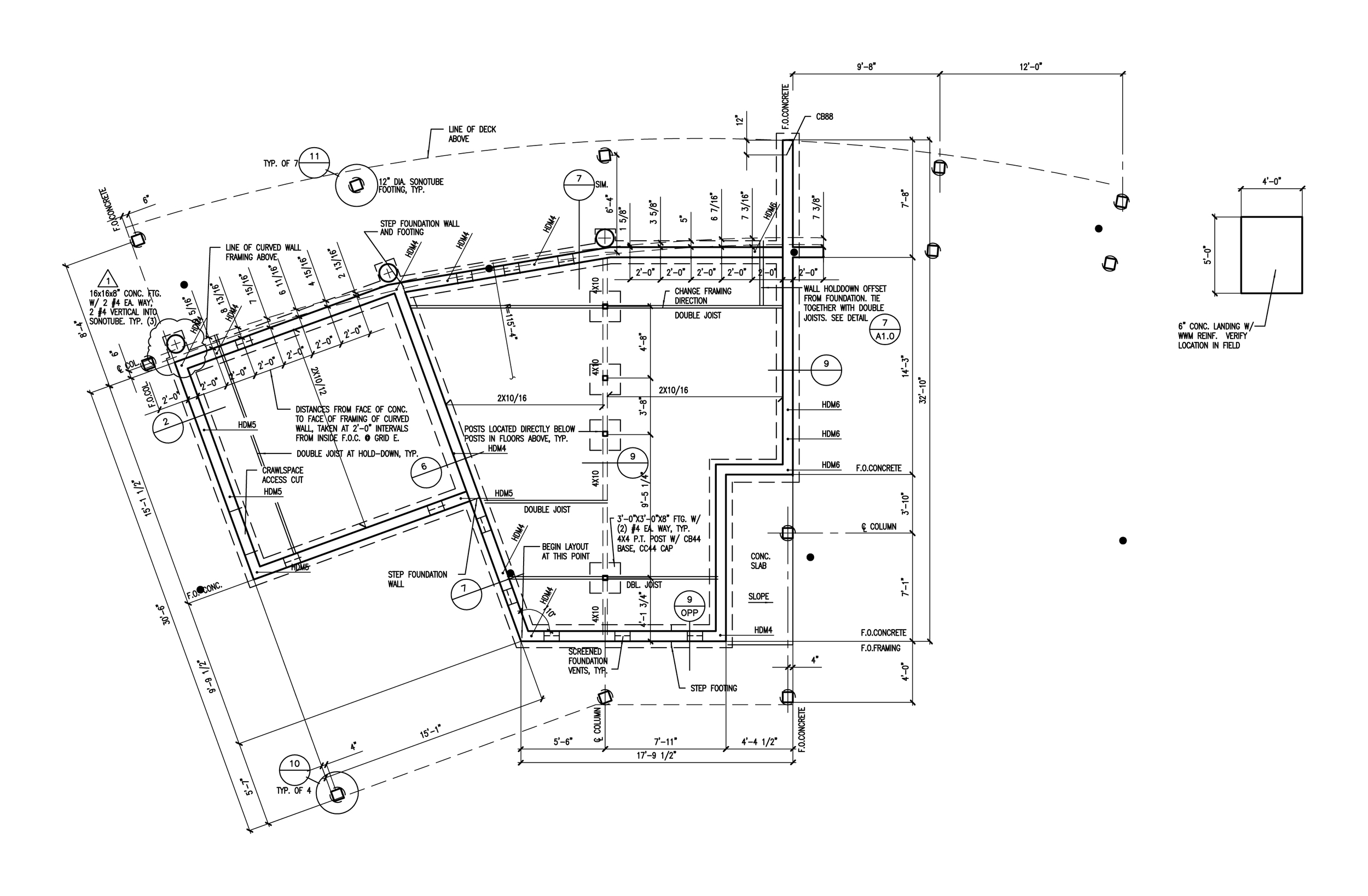
The house structure performed very well throughout the several 6+ magnitude earthquakes that occurred during the four years that we lived in the house. There were no cracks in the drywall, which were designed with generous rebates where they meet the framing. Additionally, the major structure of the house is supported on posts which allow for some movement above.
Point White Drive Elevs. & Sects.
Earthquake Zone-
Another fascinating aspect to this house was that the location was a seismic zone- level four. During the first two years that we lived in the house we experienced several earthquakes between magnitude 4 and magnitude 6. The house sat directly on top of the Seattle fault. When ever there was a tremor, we could hear the earth shaking beneath us with a sound that reminded us of thunder. The house performed very well by moving with the earth. The hold downs that were installed periodically to each wall stud and anchored into the cast in place concrete foundation wall provided resistance against lateral movement of the structure. The shaking of the earth was translated into the upper part of the structure half of which was supported by posts on Solatube which allowed for a certain amount of movement in order to avoid cracking of wallboard or other finishes in the house. The drywall finishes were always terminated with generous gaps between the factory edge of the wallboard and the timber column that formed the framing of the house. The earthquakes would frequently cause plasterboard cracking in my neighbors houses because of the extensive expanses of drywall finishes which were un-interrupted by such framing members. Additionally, the long curving wall of the south façade provided a great deal of stability for the large laminated glass windows that were framed inside of the curving wall.
The curving deck that ramped up and provided a bridge from the Eastmond road to the front door of the house was an independent structure from the house. The house was completely sealed from the weather while the deck provided its own structure from pressure-treated Cedar joists and Douglas fir posts with cedar decking that's curved with the south façade. The handrails of this bridge were fabricated and provided by the owner. Since the handrails also curved with the bridge, there was an inherent tension in the aircraft cable that was stretched from stanchion to stanchion. This required occasional custom-made outriggers that attached to the extended deck joists. These metal components added to the nautical feel created by the approach across the deck to the entrance of the house. The front door of the house was unsheltered by any entrance canopy. This observation news a shortcoming of the design of the house. Given a sufficient budget, the decks would have been covered completely by standing seam metal roofing and exposed framing. There was quite sufficient natural light inside the house to allow for the covering of the decks. The clear stories and the gigantic picture windows would have seen to that. Therefore, the covered bridge with cover decks would have created more shelter has one approached the house rather than standing in the rain while knocking at the front door. The covered decks would also have preserved the timber from the rain and would have created an interesting feature to the exterior of the house but for the lack of funds to pay for it.
Interior of the House-
The interior of the house is quite open plan. The front door opens into a vestibule that is presented with a curving half-height wall the other side of which is the kitchen sink. The kitchen itself has continuous countertops along the north-south sure well and returns into the dining area with an appliance bag and a location for a wood-burning stove. The vestibule has two options one is to enter the living room to the right and the other option is to enter the dining area. Either option results in the positioning the visitor in front of one of the two gigantic picture windows. The dining space is a double height space that is overlooked by the clerestory windows above and the Cal Wall shower enclosure. At night, these transparent/ translucent surfaces all glow and create an interesting object in the landscape if viewed from the exterior. From inside the house one can barely make out the human figure that might be showering behind the Cal Wall enclosure but without any definition or clarity. The double height space in the dining room is enjoined by a small seating area in front of the wood-burning stove that is back stopped by the timber framed staircase and handrails behind. This staircase is a very simple but strong sculptural elements that is prominently displayed at the north and of the double height dining space. The stringers are 6 x 12 material that has slots routed for 4 x 12 tread material. The handrail stanchions are bolted directly into the stringers on top of the 6 x 12's. A white maple handrail is attached to the tops of the stanchions while aircraft cable is stretched from one end of the stringer to the other. These handrails which occur on each stringer are replicated on the balcony above where there is a gallery for the master bedroom suite.
From the gallery above the kitchen where there is a small seating area for a piano and a wardrobe, it is possible to have panoramic views to the exterior through the 180° clerestory that extends south from above the dining table to the top of the stairs to the north. These views look east out onto the side yard where there are enormous cedar trees and to the north to the backyard where deer frequently graze and the cats wearily watch for bald eagles above. It is also possible to see the parking space on the easement road from this gallery where any visitor that may approach the house across the bridge can be identified. The master bedroom gallery has a door into the master bathroom and a door into the master bedroom. The master bedroom also has panoramic views. When seated on the bed it is possible to see the horizon for 270° from the north east to the west. The 12" x 12" windows that continuously circumvent the room are double glazed and provide excellent natural light for the space. There is also an openable skylight over the bed for summertime cooling. Firecode required us to introduce a means of egress from this third story bedroom that required two of the windows to be converted into full height openable windows as a fire escape. The master bathroom which is mostly enclosed by translucent Cal Wall material has a full shower platform that includes a 6 1/2 foot long claw-foot porcelain enamel bathtub. The surface area around the toilet and the hand wash basin is surfaced with granite floor tile. While seated in the bath or on the toilet magnificent views across Rich passage are possible with natural ventilation just a handcrank away.
The master bedroom suite feels like the bridge of a ship. The panoramic views, the ability to communicate with the lower living area from above, the privacy and the spaciousness all work together to create a special escape when resting on the third floor of the house. The temperature on this upper-level also benefited from the rising heat in the house, creating a very comfortable space to live in while the kitchen was rarely very hot because of the open plan of the house. If the temperature became too hot on the third floor there were a dozen different Opera brawl windows that could be opened including a skylight over the gallery and a skylight over the master bed to vent heat from the house. It rarely gets very hot in the Puget Sound with the temperature never going above 90° and rarely going below freezing during the winter. These mild temperatures lent the design of the house to significant number of openings and large expanses of glass to enjoy the natural environment around us. The propane fired boiler delivered hydronic heat to slant fin radiators in each of the bedrooms and the living spaces. The house would burn through 500 gallons of propane every three months. The well provided an endless supply of free water to the house and we shared water from the well with an adjoining neighbor who constructed a house on an acre of land that was subdivided off of our 3 acre plot in 1999. The community around us was populated by small families who were all dependent upon the same easement road to access and eat grass from their properties. As we would discover, everyone needed to use the easement road for access but very few people offered to help the maintenance of this road. In order to sell it 1 acre piece of land to a third party we had to promise to upgrade the road by widening it and introducing drainage ditches to it. We carried out this work and we paid for 100% of it. The improvements to the road limited the damage that rainwater caused to the road during the rainy season which in Seattle lasts about nine months of the year. The people living around us all benefited from the improvements to the road and they were very grateful. Eventually into thousand and three, we chose to rent our house to others so that we could live on the East Coast for a period of time while I started a new business in Solar. Eventually we sold the house in 2007 and terminated our relationship with Bainbridge Island which had lasted since 1993.
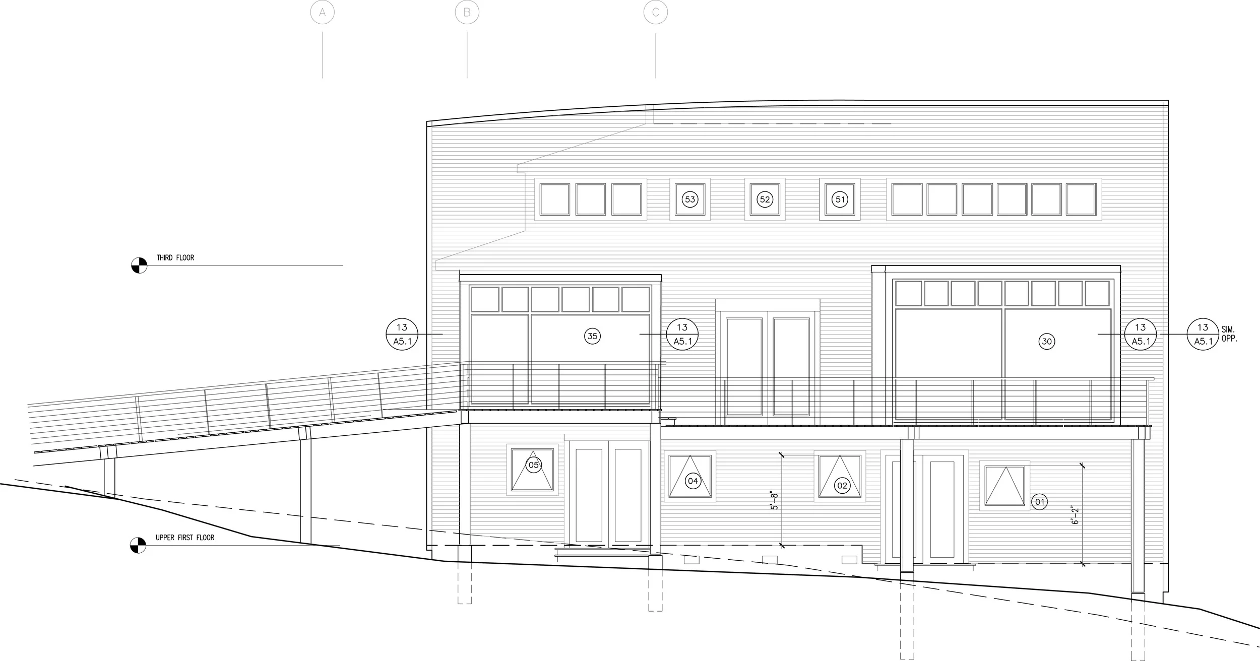
The inhabited wall that curves across the landscape with the curvature of the coastline and allows for splayed views from inside the house is the foil into which all of the occupied space plugs into and sees out of. The wall is clad with beveled cedar siding that curves and bends with the geometry of the curving wall. The formal entrance for foot traffic that approaches the house is a sloping ramp that follows the curve of the south elevation. This bridge allows for strong views into Rich passage at Fort Ward.

All bedrooms, all bathrooms, the dining room, kitchen and living room all have windows that view out of the south elevation as it curves across the landscape. All of these spaces are benefiting from the southern sky as the sun moves across it from morning until night.

At ground level, there is a strong relationship with the outdoors as the house allows for a vehicle to be parked under the upper floor. This undercroft space has a door that provides access to the boiler room which also contains the well-controls and the electrical panel. This utility room is separated by a 2hr. fire separation and is hermetically sealed from the occupied spaces of the ground floor and vented through the exterior door to protect against boiler emissions.

The building plan relegates the lesser occupied spaces of the house to the north end of the house where the stair circulation and the studio are located. This strategy allows for views to the north from the stairs and the hallways and the studio whenever they are occupied.

The internal organization of the house, which emphasizes views to the south through the curving wall, is reflected in the exterior massing of the upper floors and the ground floor and is expressed in the east elevation. On the east elevation – it was planned to add onto the house and to extend the curving Southwall further to the east.
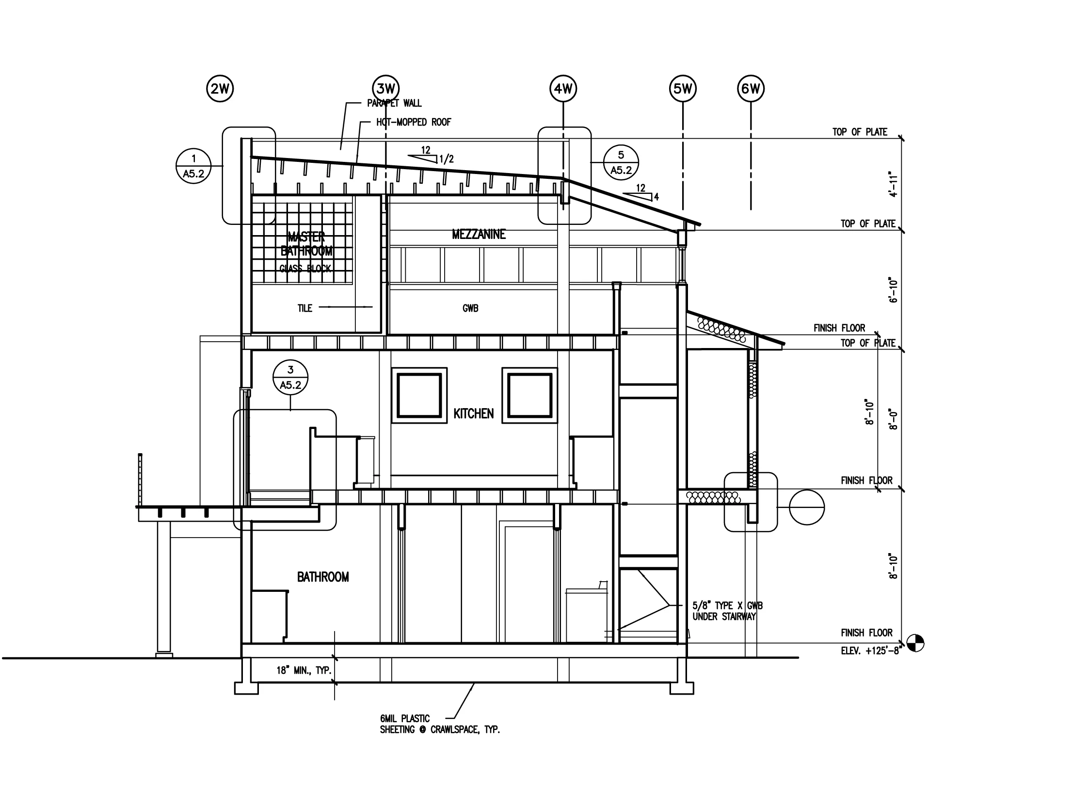
Views from each bathroom to the south are a strong connection with the water in Rich Passage. Formal entry to from the deck is primarily 4 foot traffic.
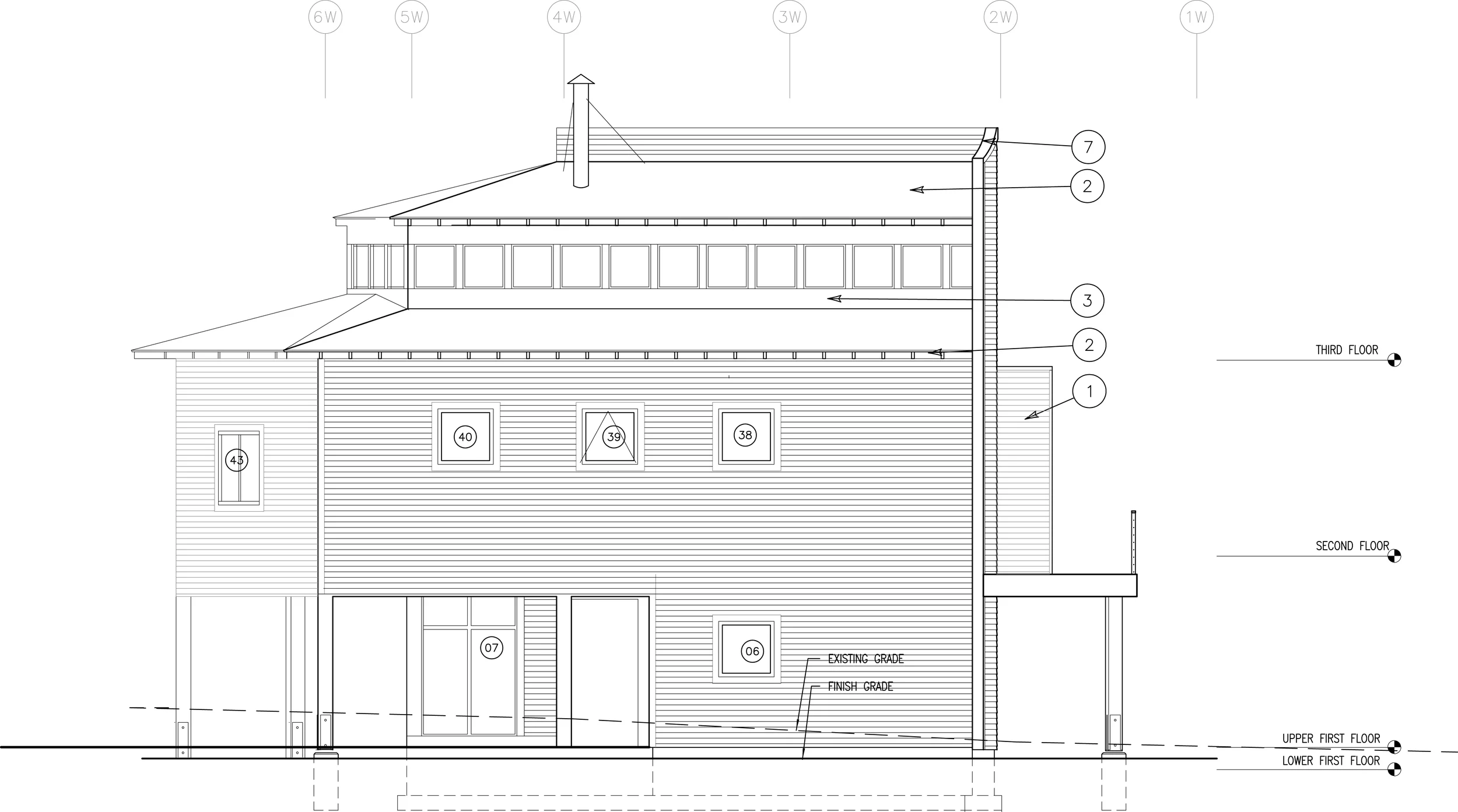
The rights-of-way traffic on the easement road goes past the east side of the house and creates a somewhat public exposure to the east elevation. Therefore, the dining room is protected from any views inside the house from the west. There are views from the gallery on the upper level through the clerestory to the west side to the north side of the house that are panoramic.
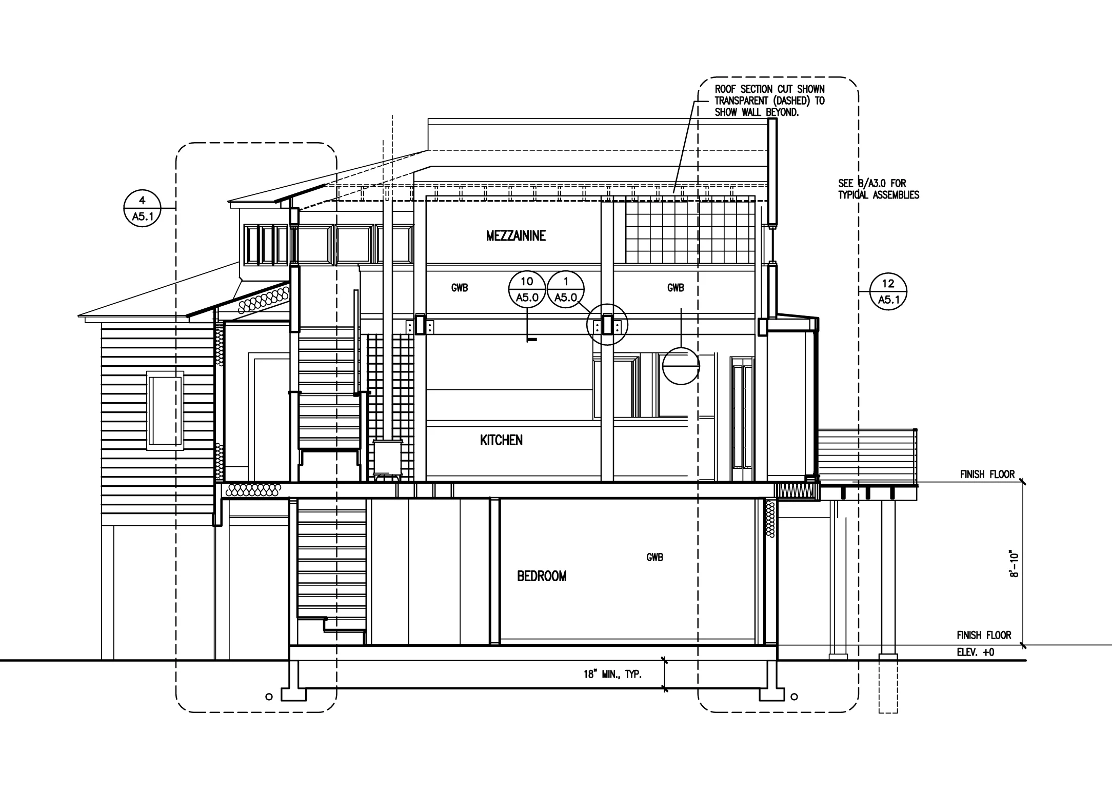
The organization of the west part of the house allows for open plan- kitchen, dining/ entrance hall/ stairway with vertical interaction to the gallery above. A piano on the gallery above is audible everywhere! The downstairs bedroom is the acoustically separated from the dining room using acoustical insulation in the floor. Foot travelers using the bridge to access the formal entry are always visible from the dining room as they cross the deck to the front entrance.

The master bedroom roof structure is designed to contain that occupied space without the need for any attic space. The slopes on the roof are designed to resolve themselves into a parapet that is on the same level as the south wall parapet. All of these parapet walls have to accommodate the roof drainage and all flashings for that galv-alum roof. There is a down-standing beam over the Bedroom that allows for a 6'-4" head height.
Point White Drive Photos
After completing the Diploma of Architecture at the Architectural Association School of Architecture in July 1993 my wife and I traveled to Bainbridge Island for a one-month house-swap. The island is off the coast of Seattle and is accessible by ferry from downtown. There are numerous architecture firms in Seattle and this opportunity to visit the Pacific Northwest came with several job interviews. The economy in the early 1990s was depressed and there was high unemployment among architects. We returned to London to work for another two years. It was during this two year period that I completed the design and construction of a Functional Brain Imaging Laboratory for the Welcome Trust in Queens Square, London for the Royal Institute of Neurology while employed by the Devereux Partnership. In 1995 I completed my RIBA part three examination and made plans to relocate to Bainbridge Island. We initially looked at existing homes to purchase for our family. We found a 3 acre piece of land on the south end of Bainbridge Island that had magnificent views of Rich Passage, part of the Puget Sound that comprises the body of water off of the south end of Bainbridge Island.
Drilling for Water- a first step
The prospect of designing and building our own home came with a great deal of responsibility and risk for the development of the land. Since there is no utility water supply to many locations on Bainbridge Island it was necessary to drill a water well. In order to purchase the land, the feasibility of striking water had to be explored prior to making a offer on the land. Hence, a well drilling rig required access to the low point on the land which meant that we had to cut some trees and perform some initial clearing. The clearing of trees required us to obtain a clearing permit. We had the permission of the land owner to clear a limited number of trees in order to drill an exploratory water well. Once we struck water we determined that there was more than adequate water pressure to supply our house as well as one or two other houses. The water we found was also clear of any calcium deposits or other contaminants that can often require domestic water to be treated on-site.
After having accepted our offer for the land, the owners gave us permission to carry on clearing the land of the trees that we intended to mill and to have kiln dried for our house's decking material, siding material, beams, posts, interior trim and soffit material. The logger who cut the trees required a beam schedule from me in order to determine the length of the logs that were required for our house's timber package. The design for the house had evolved sufficiently for us to provide him with the information he needed in order to start making the timber from the logs. We had originally intended to design a timber-framed home with traditional exposed beams and brackets that are common to the craftsman style of the Pacific Northwest. The less-expensive option was to balloon frame the house in conventional house construction methods and to have a limited number of exposed beams and columns with custom bracketry to complete the joinery. Therefore, all of the conventional framing material required for the "two by" construction was purchased from the lumberyard and all of the beams and columns and all of the decking, siding and soffit material was provided from our milling operation.
After clearing the land and drilling the freshwater well, the need for a septic design was next. We hired a civil engineer and a septic field designer to provide us with an application to the department of health for our house's septic plan. This was a risky undertaking because gravity fed drainfields were becoming a liability to many home owners and the town was contemplating a ban on this type of septic design. This was because the ground was quite often not permeable enough to allow for the percolation of human waste into the ground. Our septic designer added a great deal of sandy soil to the design of our septic field which was perforated pipe encased in granite gravel. Soon we had a permitted septic design for our piece of land and that concluded the contingencies that we allowed for and the purchase of our 3 acre lot was completed in December 1995.
What remained for us to do was to complete a Wildlife Survey of our land to search for any bald eagles nests or other wildlife that could impede our construction permit. A wildlife specialist was employed to come in and do a Wildlife Survey for us. This resulted in no obstacles to our building permit and we were soon able to begin interviewing contractors for our house project. At the time that I was beginning to design the house, I was employed on a $160 million prison project for the State of Washington by NBBJ. I had completed a three-dimensional framing model of the house for the purposes of quantifying my timber package. A friend of mine who was an architect at the Miller Hull company asked if I could use some help with the construction drawings. Peter Wolff became an employee of the construction contracting company that I had engaged to build my house. Peter carried out all of the construction drawings for the house during the 1996 timeframe and construction began in 1997. The Reijnen Company was the builder of the house. The size of the house as defined in my three-dimensional framing model was reduced in order to achieve a budget of approximately $300,000. Peter was able to import my three-dimensional framing model into AutoCAD and to produce the various two-dimensional sections, plans, and elevations of the house.
Designing a House while working as an Architect- Day Job / Night Job
Design and Construction of the house during this initial period while employed by NBBJ was a full time occupation. During the period of time that I was designing the house, I was also part of large team of architects designing the Stafford Creek Corrections Center in Grays Harbor, Washington. I was also briefly involved in Swedish Hospital Phase 5 Surgery in the early days of the house project. Also during this period, the contents of our home from London was shipped in a 40 foot shipping container to our rental property on Bainbridge Island. We had arrived in Seattle in September of 1995 and our newborn son turned one on October 1. Just prior to starting construction of the house in April 1997, Josephine our third child was born to us on December 30, 1996. Presented with the same opportunity, in hindsight – I'd've had less on my plate.
The design of the house was driven largely by the geography of the site and the enormous Douglas firs that paced across the property, controlling views out of the site to the south, out to the body of water that presented us with so much maritime traffic, the sound of the ferries, the naval ships and the sounds of the sea lions in the water calling out below. The presence of and the movement of ships past our house was calling for the nautical architecture that I embraced so wholeheartedly with the south elevation of the house. The views out of the site and the southerly aspect of the property were what steered me towards the large expanses of glass. The large rectangular forms that bulge briefly through the curving wall of the south elevation created an animated interactive space that brought the outdoors in and the indoors out. During the summer, the curving deck, which wrapped around the major living spaces was a space which was next to the large plates of laminated glass that separated us from the interior of the house and frequently created an interesting hybrid space that blurred the lines between the two.
Many of the components of the house were owner provided. As discussed previously, all of the decking, siding, interior trim, soffit material, beams and posts for the house were owner provided. In addition to that, all door hardware, appliances, electrical fixtures, and balustrades were owner provided to the contractor. The deck was constructed of custom milled cedar decking which dimensionally had to be able to be bent to match the radius of the curve of the South Wall. This resulted in 3 inch wide decking material. All of the floorboards of the deck workbench in order to follow the bending cedar siding of the vertical surface. The handrail on the balustrade also had to curve with the south elevation. This material was bolted to custom stanchions that were hot dipped and lag bolted to a curving 2" x 12" facia board that terminated the 2" x 8" joist ends of the deck. In order to stabilize the curving balustrade, outriggers which hold the balustrade outwards to compensate for the inward force of the tensioned aircraft cable were attached to periodic cantilevering joists.
Another owner provided item was the detention pond which collected all of the storm water off of the driveway and all of the storm water off of the roofs. The detention pond was located to the east of the house and was frequently filled with water in the Pacific Northwest climate that measured rainfall in feet not inches. There was an excessive amount of organic debris that was blown off of the Douglass firs that collected on the roofs and would normally clog gutters but for the gutter-less design of our storm water system. All of the roofs were standing seam metal Galv-alum roofs. The Douglas Fir leaves which collected on the roof were washed down hill across the cascading slopes of standing seam metal. A French drain surrounded the house and egressed water into the detention pond through under ground pipes. The French drain was entirely constructed from Granite drain rock. This granite drain rock apron which surrounded the house created a 12 foot surface transition from green grass to granite rock. The organic debris from the roofs was easily collected at ground level periodically while the water continued on to deposit in the detention pond.
Earthquake Zone-
Another fascinating aspect to this house was that the location was a seismic zone- level four. During the first two years that we lived in the house we experienced several earthquakes between magnitude 4 and magnitude 6. The house sat directly on top of the Seattle fault. When ever there was a tremor, we could hear the earth shaking beneath us with a sound that reminded us of thunder. The house performed very well by moving with the earth. The hold downs that were installed periodically to each wall stud and anchored into the cast in place concrete foundation wall provided resistance against lateral movement of the structure. The shaking of the earth was translated into the upper part of the structure half of which was supported by posts on Solatube which allowed for a certain amount of movement in order to avoid cracking of wallboard or other finishes in the house. The drywall finishes were always terminated with generous gaps between the factory edge of the wallboard and the timber column that formed the framing of the house. The earthquakes would frequently cause plasterboard cracking in my neighbors houses because of the extensive expanses of drywall finishes which were un-interrupted by such framing members. Additionally, the long curving wall of the south façade provided a great deal of stability for the large laminated glass windows that were framed inside of the curving wall.
The curving deck that ramped up and provided a bridge from the Eastmond road to the front door of the house was an independent structure from the house. The house was completely sealed from the weather while the deck provided its own structure from pressure-treated Cedar joists and Douglas fir posts with cedar decking that's curved with the south façade. The handrails of this bridge were fabricated and provided by the owner. Since the handrails also curved with the bridge, there was an inherent tension in the aircraft cable that was stretched from stanchion to stanchion. This required occasional custom-made outriggers that attached to the extended deck joists. These metal components added to the nautical feel created by the approach across the deck to the entrance of the house. The front door of the house was unsheltered by any entrance canopy. This observation news a shortcoming of the design of the house. Given a sufficient budget, the decks would have been covered completely by standing seam metal roofing and exposed framing. There was quite sufficient natural light inside the house to allow for the covering of the decks. The clear stories and the gigantic picture windows would have seen to that. Therefore, the covered bridge with cover decks would have created more shelter has one approached the house rather than standing in the rain while knocking at the front door. The covered decks would also have preserved the timber from the rain and would have created an interesting feature to the exterior of the house but for the lack of funds to pay for it.
Interior of the House-
The interior of the house is quite open plan. The front door opens into a vestibule that is presented with a curving half-height wall the other side of which is the kitchen sink. The kitchen itself has continuous countertops along the north-south sure well and returns into the dining area with an appliance bag and a location for a wood-burning stove. The vestibule has two options one is to enter the living room to the right and the other option is to enter the dining area. Either option results in the positioning the visitor in front of one of the two gigantic picture windows. The dining space is a double height space that is overlooked by the clerestory windows above and the Cal Wall shower enclosure. At night, these transparent/ translucent surfaces all glow and create an interesting object in the landscape if viewed from the exterior. From inside the house one can barely make out the human figure that might be showering behind the Cal Wall enclosure but without any definition or clarity. The double height space in the dining room is enjoined by a small seating area in front of the wood-burning stove that is back stopped by the timber framed staircase and handrails behind. This staircase is a very simple but strong sculptural elements that is prominently displayed at the north and of the double height dining space. The stringers are 6 x 12 material that has slots routed for 4 x 12 tread material. The handrail stanchions are bolted directly into the stringers on top of the 6 x 12's. A white maple handrail is attached to the tops of the stanchions while aircraft cable is stretched from one end of the stringer to the other. These handrails which occur on each stringer are replicated on the balcony above where there is a gallery for the master bedroom suite.
From the gallery above the kitchen where there is a small seating area for a piano and a wardrobe, it is possible to have panoramic views to the exterior through the 180° clerestory that extends south from above the dining table to the top of the stairs to the north. These views look east out onto the side yard where there are enormous cedar trees and to the north to the backyard where deer frequently graze and the cats wearily watch for bald eagles above. It is also possible to see the parking space on the easement road from this gallery where any visitor that may approach the house across the bridge can be identified. The master bedroom gallery has a door into the master bathroom and a door into the master bedroom. The master bedroom also has panoramic views. When seated on the bed it is possible to see the horizon for 270° from the north east to the west. The 12" x 12" windows that continuously circumvent the room are double glazed and provide excellent natural light for the space. There is also an openable skylight over the bed for summertime cooling. Firecode required us to introduce a means of egress from this third story bedroom that required two of the windows to be converted into full height openable windows as a fire escape. The master bathroom which is mostly enclosed by translucent Cal Wall material has a full shower platform that includes a 6 1/2 foot long claw-foot porcelain enamel bathtub. The surface area around the toilet and the hand wash basin is surfaced with granite floor tile. While seated in the bath or on the toilet magnificent views across Rich passage are possible with natural ventilation just a handcrank away.
The master bedroom suite feels like the bridge of a ship. The panoramic views, the ability to communicate with the lower living area from above, the privacy and the spaciousness all work together to create a special escape when resting on the third floor of the house. The temperature on this upper-level also benefited from the rising heat in the house, creating a very comfortable space to live in while the kitchen was rarely very hot because of the open plan of the house. If the temperature became too hot on the third floor there were a dozen different Opera brawl windows that could be opened including a skylight over the gallery and a skylight over the master bed to vent heat from the house. It rarely gets very hot in the Puget Sound with the temperature never going above 90° and rarely going below freezing during the winter. These mild temperatures lent the design of the house to significant number of openings and large expanses of glass to enjoy the natural environment around us. The propane fired boiler delivered hydronic heat to slant fin radiators in each of the bedrooms and the living spaces. The house would burn through 500 gallons of propane every three months. The well provided an endless supply of free water to the house and we shared water from the well with an adjoining neighbor who constructed a house on an acre of land that was subdivided off of our 3 acre plot in 1999. The community around us was populated by small families who were all dependent upon the same easement road to access and eat grass from their properties. As we would discover, everyone needed to use the easement road for access but very few people offered to help the maintenance of this road. In order to sell it 1 acre piece of land to a third party we had to promise to upgrade the road by widening it and introducing drainage ditches to it. We carried out this work and we paid for 100% of it. The improvements to the road limited the damage that rainwater caused to the road during the rainy season which in Seattle lasts about nine months of the year. The people living around us all benefited from the improvements to the road and they were very grateful. Eventually into thousand and three, we chose to rent our house to others so that we could live on the East Coast for a period of time while I started a new business in Solar. Eventually we sold the house in 2007 and terminated our relationship with Bainbridge Island which had lasted since 1993.

The approach to the house from the road has cedar 2" x 3" decking that curves up the gentle slope to the house.
Approach to the house by car up the steep hill is a study in the changing geometry of the south face.
Western face is visible from gravel road passers-by and is punctuated by windows that provide privacy to the spaces that is overlooked.
The view out of the site to the south has two opportunities to see the marine passage below the house. These two views set up the 20 degree angle which splays the living room from the dining space.


The long avenue of Douglas Fir Trees that pace across the landscape are preserved and a Giant Western Red Cedar which once stood where the house is, now blankets the walls and deck with bevelled siding and decking.


Formal entry to the house from the road is a serene approach up the curving ramp with an elegant balustrade of nautical turnbuckle hardware with post tensioned steel cables and stanchions.
The north face of the house allows for significant outdoor shelter for activities, a workshop, parking and access to the boiler room and well controls- a space which is hermetically sealed from the downstairs bathrooms. The majesty of the Douglas Fir Trees to the south can be seen beyond.

The house is circumvented by a granite drainrock apron that collects rainwater in perforated pipe (along with driveway storm water) and pours it into a landscaped pond downslope from the house. The apron also acts as a mud free, tactile surface to walk on prior to entry through the sheltered ground floor door.








Stanford University, College of Mechanical Engineering- Schematic Design
Project Summary:
Architecture Firm: MBT Architecture, Seattle
Client: Stanford University, College of Mechanical Engineering
Date of Construction Completion: 2002
John Millard's Role: Project Architect for Combustion Science Laboratories (High Pressure Combuster Lab & Engine Laboratory)
Duration of Design Effort: Schematic Design- July/ November 1999, Design Development- Nov.'99/ May 2000, Construction Documentation- May/ October 2000
John Milard joined MBT architecture in September 1998. After working on several laboratory buildings in MBT's Seattle Office, John was asked to join a team of architects in the San Francisco office of MBT to design a new Mechanical Engineering Laboratory for Stanford University's College of Mechanical Engineering. John's scope of work was to design the laboratories for the combustion science part of the building. The schematic phase of design had begun in June 1999. John worked closely with the primary investigators of the combustion science department and designed two laboratories: one for the high-pressure combustor and another for the engine laboratory. Each of these laboratories were highly complex in their requirements due largely to the excessive vibration that was created in each one of the spaces.
The engine laboratory was designed for testing and experimentation of many different kinds of combustion engines. While fuel cells are not strictly combustion engines, fuel cells were tested in the engine laboratory and used hydrogen fuel which is a combustible gas. Other fuels which needed to be stored on site were leadfree gasoline, diesel fuel, jet fuel, oil, and many other gases that required storage and delivery systems to various experiments in the engine lab.
In order to keep the noise from the experiments in the engine lab to a minimum, an acoustical engineer was retained by the team to design a resilient envelope that would eliminate vibration from transferring into the structure of the building. Additionally, in order to manipulate engine blocks and other heavy objects in the engine laboratory a traveling bridge beam crane was required to be suspended from the ceiling of the engine laboratory. In order for this crane to be functional, all of the other overhead services in the engine laboratory had to accommodate the movement of the cream across the floor space. Therefore, all of the exhaust ducts fuel lines, sprinkler pipes, lighting, power and communications cable trays, dedicated engine exhaust and other overhead service components had to be carefully planned around the movement of the crane.
The engine laboratory also had a complex series of slab depressions that accommodated everything from excess sprinkler water to a large dynamometer used to absorb the energy from experimental car acceleration. This dynamometer required base isolation in order to protect the slab from experiencing vibration from the dynamometer.
In order to store the vast amount of fuel required to conduct combustion science experiments in the engine lab, a hazardous substances galley was required to be constructed next to the engine lab that would have a separate hazardous substances occupancy rating and would be designed to have explosion panels to defray the force of an explosion that might occur in this separate occupancy.
The primary steel structure of the building was to be defended against these vibrations that emanated from the experiments in the engine laboratory at all possible costs. The acoustical engineer for the project designed a resilient envelope that was comprised mainly of multiple layers of gypsum wall board. This primary defense against noise being transmitted into the teens collaborative laboratories just one floor above the entry lab required additional structure to support the resilient envelope. An array of light gauge metal joists were hung from the concrete slab by springs.
These fittings known as spring hangers suspended two layers of 5/8" gypsum wallboard above the crane rails of the crane structure in order to isolate the GWN from crane rail vibration.
And array of strut was required across the entire ceiling surface to suspend components for experiments as well as lighting and other overhead services. In order to present the transference of vibration from these components into the struts and consequently into other parts of the building structure –special detailing of these assemblies was necessary in order to keep noise out of the rest of the building. John Millard was responsible for detailing these conditions that might otherwise have resulted in a conventional detail that transmitted vibration. John worked closely with the acoustical engineer who had review and approval rights to all of the work that was produced. These details are shown in the construction documents section of this portfolio.
The schematic design phase of the mechanical engineering building project was carried out between June 1999 and September 1999. During this time the specifications, user requirements, equipment specifications, service requirements and other engineering related disciplines were all conferenced with the owner during this time. The three-dimensional coordination models shown to the clients were presented to the owner in a review and approval process with the facility management at Stanford University College of Mechanical Engineering.
Schematic Design Issue: Engine Laboratory Occupancy Classification
Summary: This is to confirm the occupancy classification of the Engine Laboratory portion of the above, mixed-occupancy project. The Architect has reviewed the issue of an S-3 versus H-4 occupancy classification at meetings with the above agency representatives on January 28th and May 5th, 1999 (Tom Whisler not present at the second meeting). Since the building code interpretation on this matter is not an obvious one and the occupancy classification significantly impacts the design and construction requirements, it is important that the classification be firmly established prior to entering the design development phase of the project.
Background: The area in question contains 2,070 square feet of space on the first floor of the building. It is divided into the Engine Room and Engine Control Room. The function of these rooms is best summed up by information provided by the future users: "The engine lab is used both for operational engine tests and for dissection and modification of engines. Engine testing involves operation of an engine attached to a loading device (dynamometer) over a range of speeds and loads. Performance data are collected and analyzed. Exhaust emissions are sampled and analyzed. Alternative engine systems (ignition, control programming, fuel injection, etc) are studied. Engines are dissected as part of reverse-engineering studies. Engines are also modified as needed for the engine experiments. Note that many normal auto-shop activities do not take place in the engine lab: tank cleaning, welding, painting,… The activities in the lab more closely resemble those of a combustion research laboratory than they do an auto repair facility." It should be noted that in addition to the absence of welding, no open flames are used in this space. Personnel are primarily stationed in the Control Room during operation of the engines, although they occasionally enter the Engine Room to make an adjustment. Most importantly, materials (fuels, engine lubricants, et cetera) storage is in the H-2 space, next door. Combustible fuels are piped directly to the engines in closed systems.
Conclusion: S-3 Occupancy Definition: “…include repair garages where work is limited to the exchange of parts and maintenance requiring no open flame or welding…” H-4 Occupancy Definition: “Repair garages not classified as H-4.” The project code analysis currently assumes the worst-case scenario in terms of occupancy-based restrictions, which is that of an H-4 classification. However, if the factor separating S-3 and H-4 is that of materials storage and use, then the programmed activities appear to occur within the limitations of the S-3 classification. Despite the user’s opinion as to what the lab activities most closely resemble, the material uses are more in alignment with that of a B-occupancy type of laboratory facility. As such, we proposed the Engine Laboratory facility be designated an S-3 occupancy.
Schematic Design Issue: Mechanical Vibration Control and Isolation Specification:
PART 1 - - GENERAL
1.1 WORK INCLUDED
A. This Section specifies the requirements for vibration control systems to be used in all phases of architectural, mechanical, electrical, and structural work.
B. This Specification provides the necessary design for the avoidance of excessive vibration and structural borne noise in the building due to the operation of machinery or equipment and/or due to interconnected piping, ductwork, conduit, or structures.
Due to the high technology nature of this facility the design criteria any exceed those of normal industrial construction. It is imperative that close attention be paid to all specifications and details for noise and vibration control.
1.4 DESIGN CRITERIA: A. Equipment, ductwork, piping and conduit shall not be installed which makes rigid contact with the structure unless it is allowed by this specification. B. Pipe Anchors and Supports: Piping supports and anchors shall not interfere with free operation of vibration isolation systems. Stiff-leg support of piping supported on Type HS, or Type FSN isolators is not acceptable. C. Ductwork: Ductwork isolation requirements are based on duct equivalent diameters. For rectangular ductwork, the equivalent diameter is the diameter of duct having the same cross-sectional area. D. Equipment Isolation Frames and Bases: Frames and bases used to support vibration isolated pumps shall be sized to provide support for pipe elbows. E. Isolation/Absorption Products: The completed installation must be free of unacceptable vibration and noise. Systems, equipment, or parts which vibrate or generate vibration unduly, or which generate or emit undue noise while in operation, shall: (1) be adjusted, repaired, or replaced as appropriate to obtain acceptable levels of vibration or noise, or (2) be supported on, or fitted with, suppression or absorption devices, or other means, which effectively prevent the transmission of vibration or noise beyond the offending item. F. Resilient Wall, Ceiling, and Floor Penetrations: Provide resilient wall and ceiling penetrations for all piping, conduit, ductwork, etc. supported on Type HS or Type FSN isolators. Refer to resilient penetration details on the Drawings.
2.2 VIBRATION ISOLATORS
A. General:
1. Metal parts of vibration-isolation units shall be as follows: Galvanizing shall meet ASTM Salt Spray test Standards and Federal Test Standard no. 14.
a. Housing: Hot-dipped galvanized or fusion epoxy coated.
b. Hardware (washers, nuts, bolts, etc.): Cadmium plated.
c. Springs shall be neoprene coated.
2. All isolators installed outdoors shall have base plates with bolt holes for fastening the isolators to the support members.
3. Isolator types are scheduled to establish minimum standards. At the Subcontractor's option, labor-saving accessories can be an integral part of isolators supplied to provide initial lift of equipment to operating height, hold piping at fixed elevation during installation and initial system filling operations, and similar installation advantages. Accessories shall not degrade the vibration isolation system.
4. Static deflection of isolators shall be as indicated in Table 15240, Vibration Isolation Schedule. All static deflections stated are the minimum acceptable deflection for the mounts under actual load.
5. The use of nested springs or of multiple parallel springs within a single mount is not permitted.
B. Unit FSN (Floor Spring and Neoprene):
1. Spring isolators shall be free-standing and laterally stable without any housing. Spring diameter shall be not less than 0.8 times the compressed height of the spring at the design load. Springs shall have a minimum additional travel to solid equal to 50 percent of the actual deflection. Springs shall be so designed that the ratio of horizontal stiffness to vertical stiffness is approximately 1. All mounts shall have leveling bolts.
2. The spring element in the isolator shall either be set in a neoprene cup and have a steel washer to distribute the load evenly over the neoprene, or each isolator shall be mounted on a unit DNP isolator. If the DNP isolator is used, a rectangular bearing plate of appropriate size to load the pad uniformly in the range of 40 to 50 psi shall be provided. If the spring isolator is supplied with a neoprene friction pad, a stainless steel, aluminum, or galvanized steel plate shall be used between the friction pad and the DNP isolator. The DNP isolator, separator plate, and friction pad shall be permanently adhered to one another and to the bottom of the bearing plate.
3. If the isolator is to be fastened to the building structure and a unit DNP isolator is used under the bearing plate, neoprene grommets shall be provided for each bolt hole in the base plate. Bolt holes shall be properly sized to allow for grommets. Hold down bolt assembly shall include washers to distribute load evenly to the grommet. Bolts and washers shall be galvanized.
4. Unit FSN isolators shall be one of the following products, or approved equal, with the appropriate neoprene pad (if used) selected from Unit DNP:
a. Type SLF: M.I.
b. Type FDS: K.N.C.
c. Type AC or AD: V.M.C.
C. Unit FSNTL (Floor Spring and Neoprene Travel Limited):
1. Spring isolators shall be free-standing and laterally stable without any housing. Spring diameter shall be not less than 0.8 times the compressed height of the spring at the design load. Spring shall have a minimum additional travel to solid equal to 50 percent of the actual deflection. Springs shall be so designed that the ratio of horizontal stiffness to vertical stiffness is approximately 1. All mounts shall have leveling bolts. All mounts shall have vertical travel limit stops to control extension when weight is removed. The travel limit stops shall be capable of serving as blocking during erection of the equipment. A minimum clearance of 1/4 inch shall be maintained around restraining bolts and between the limit stops and the spring to avoid interference with the spring action.
2. The spring element in the isolator shall either be set in a neoprene cup and have a steel washer to distribute the load evenly over the neoprene, or each isolator shall be mounted on a unit DNP isolator. If the DNP isolator is used, a rectangular bearing plate of appropriate size to load the pad uniformly in the range of 40 to 50 psi shall be provided. If the spring isolator is supplied with a neoprene friction pad, a stainless steel, aluminum, or galvanized steel plate shall be used between the friction pad and the DNP isolator. The DNP isolator, separator plate, and friction pad shall be permanently adhered to one another and to the bottom of the bearing plate.
3. If the isolator is to be fastened to the building structure and a unit DNP isolator is used under the bearing plate, neoprene grommets shall be provided for each bolt hole in the base plate. Bolt holes shall be properly sized to allow for grommets. Hold down bolt assembly shall include washers to distribute load evenly to the grommet. Bolts and washers shall be galvanized.
4. Unit FSNTL isolators shall be one of the following products, or approved equal, with the appropriate neoprene pad (if used) selected from Unit DNP
a. Type SLR: M.I.
b. Type FLS: K.N.C.
c. Type AWR-1: V.M.C.
D. Unit FN (Floor Neoprene):
1. Neoprene isolators shall be neoprene-in-shear type with steel reinforced top and base. All metal surfaces shall be covered with neoprene. The top and bottom surfaces shall be ribbed. Bolt holes shall be provided in the base and the top shall have a threaded fastener.
2. The mounts shall include leveling bolts that may be rigidly connected to the equipment.
3. Unit FN isolators shall be one of the following products or approved equal:
a. Type ND: M.I.
b. Type RD: K.N.C.
c. Type R/RD: V.M.C.
E. Unit NP (Neoprene Pad)
1. Neoprene pad isolators shall be one layer of 1/4-inch to 5/16-inch thick ribbed or waffled neoprene. Neoprene shall be 40 to 50 durometer. The pads shall be sized so that they will be loaded within the manufacturer's recommended range.
2. Unit NP isolators shall be one of the following products or approved equal:
a. Type W: M.I.
b. Type NPS: K.N.C.
c. Type Shear-Flex or Maxi-Flex: V.M.C.
F. Unit DNP (Double Neoprene Pad):
1. Neoprene pad isolators shall be formed by two layers of 1/4-inch to 5/16-inch thick ribbed or waffled neoprene, separated by a stainless steel or aluminum plate. these layers shall be permanently adhered together. Neoprene shall be 40 to 50 durometer. The pads shall be sized so that they will be loaded within the manufacturer's recommended range.
2. Unit DNP isolators shall be formed from one of the following products or approved equal:
a. Type WSW: M.I.
b. Type NPS: K.N.C.
c. Multiple Layers of Type Shear-Flex or Maxi-Flex: V.M.C.
G. Unit HS (Hanger Spring):
1. Vibration-isolation hangers shall consist of a free-standing laterally stable steel spring set into a neoprene cup, contained within a steel housing. The neoprene cup shall be manufactured with a grommet (or other element) to prevent the hanger rod from contacting the hanger housing. A steel washer shall be provided in the neoprene cup to evenly distribute load onto the neoprene.
2. The plate or washer at the top of the spring shall be welded to the spring. The hanger rod shall be securely fastened to this plate or washer using lock nuts. The hanger rod shall have a diameter not less than 5/8 inch. This design represents a modification to the unit types given below. The modification is intended to limit the side-to-side motion of the hanger rod relative to the hanger casing.
3. Spring diameter and hanger housing lower hole sizes shall be large enough to permit the hanger rod to swing through a 30 degree arc before contacting the housing. Spring elements shall have minimum additional travel to solid equal to 50 percent of the actual deflection.
4. Upper hanger rod attachment shall be made through a neoprene rubber-in-shear element designed to avoid direct contact between the hanger rod and the isolator frame.
5. Springs shall be color coded for ease of identification and removable, for field connection.
6. Unit HS isolators shall be one of the following products or approved equal:
a. Type 30N (modified): M.I.
b. Type SH (modified): K.N.C.
c. Type RSH (modified): V.M.C.
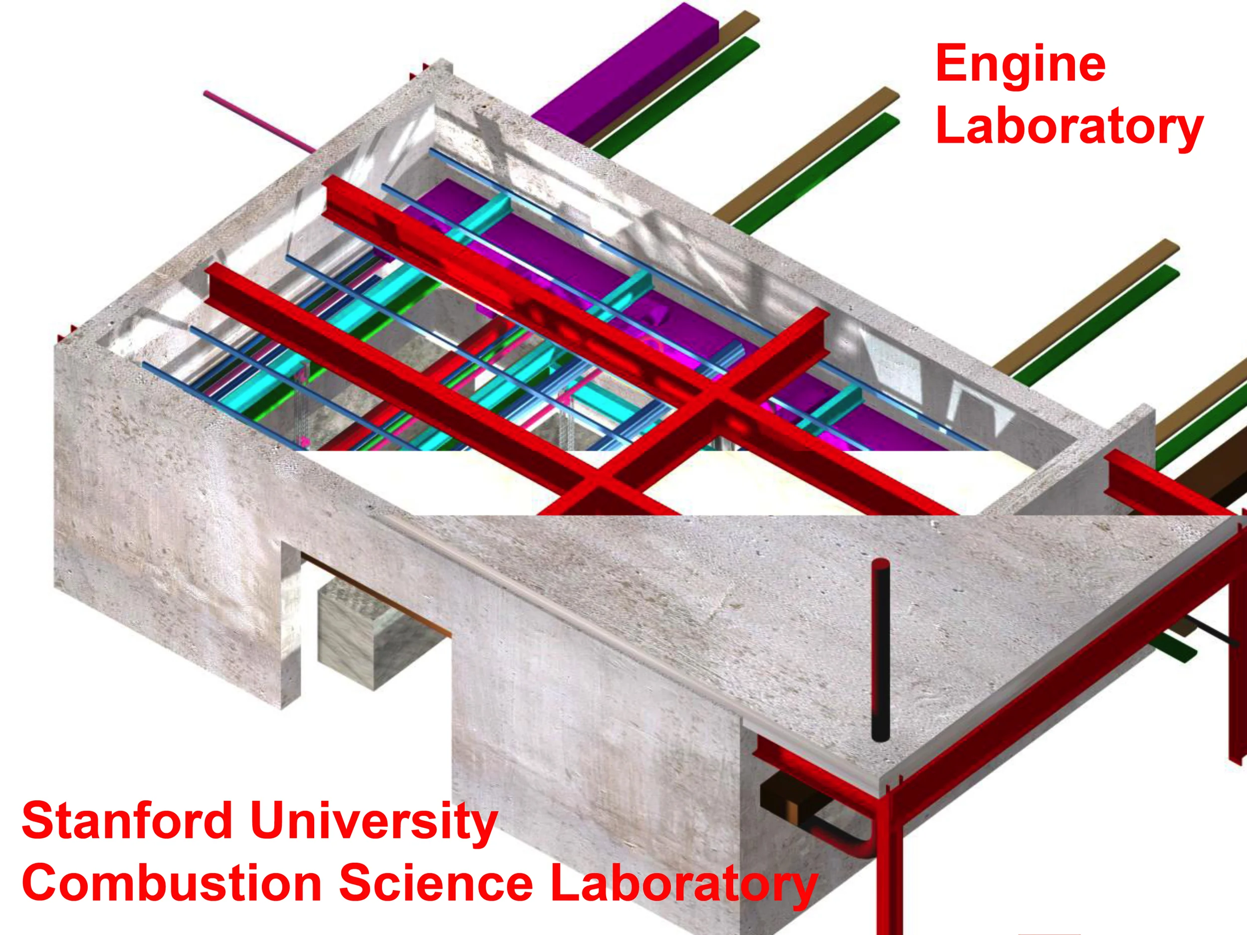
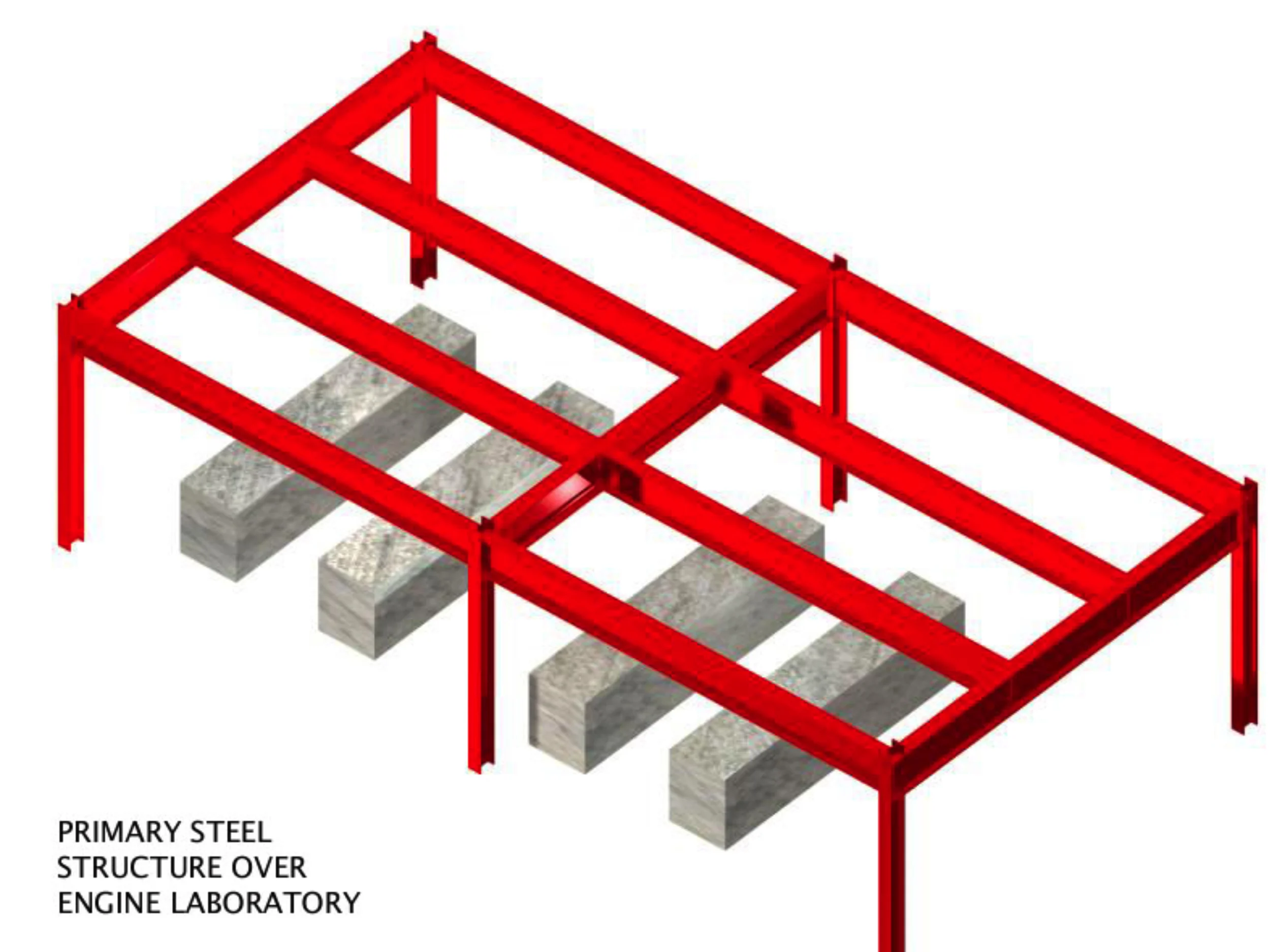
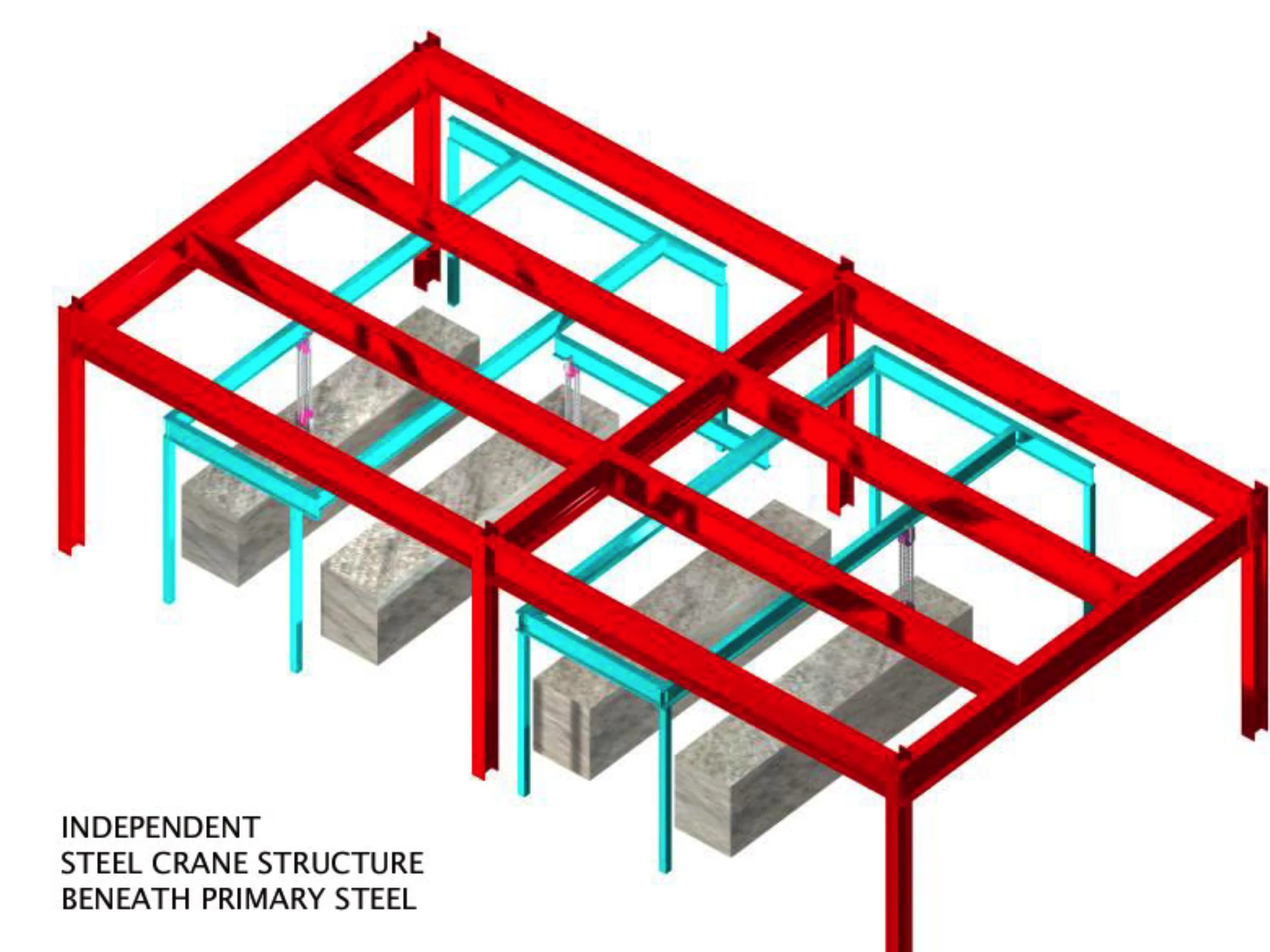
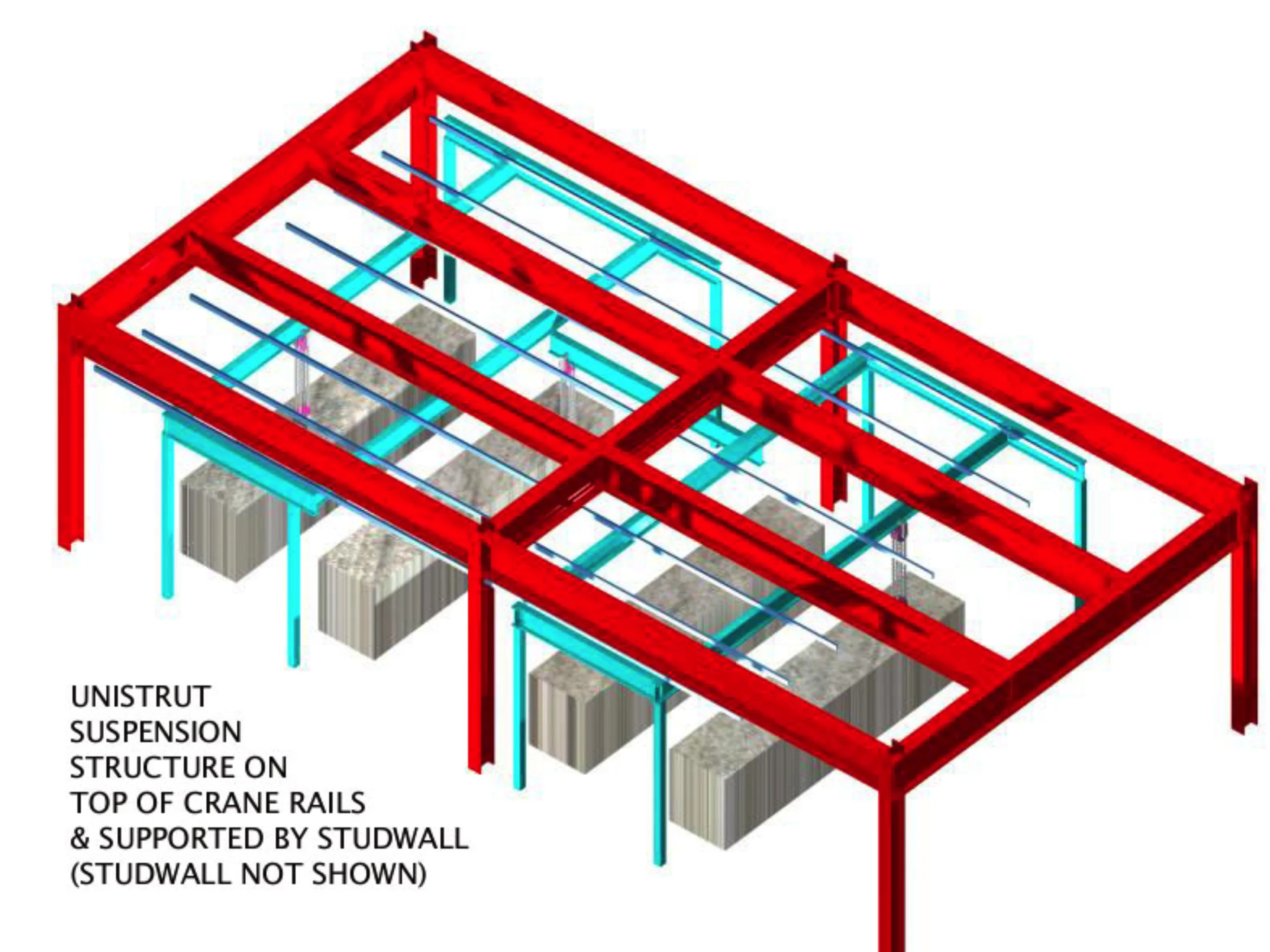
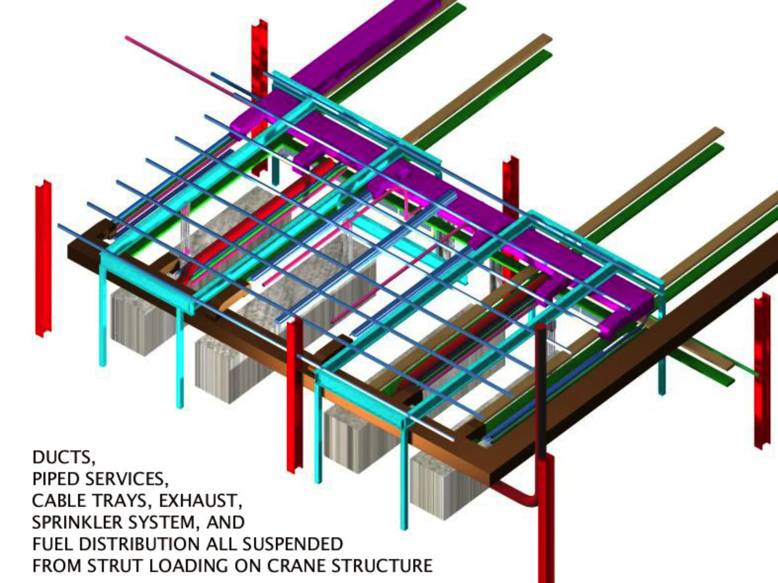
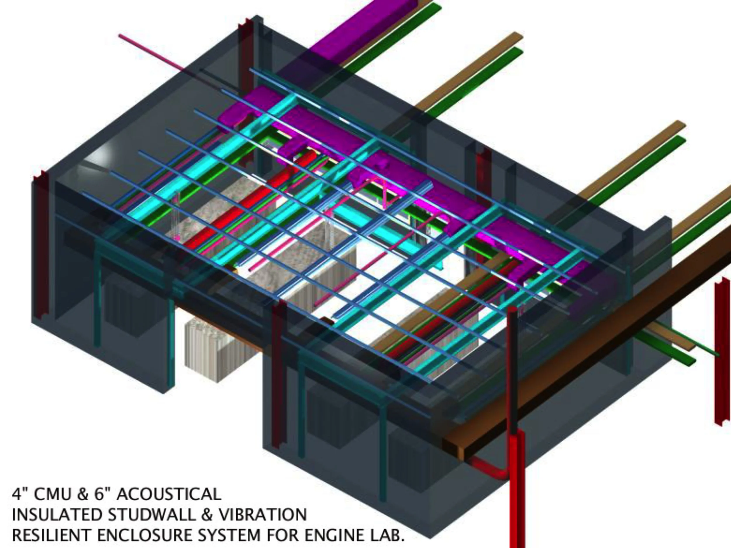
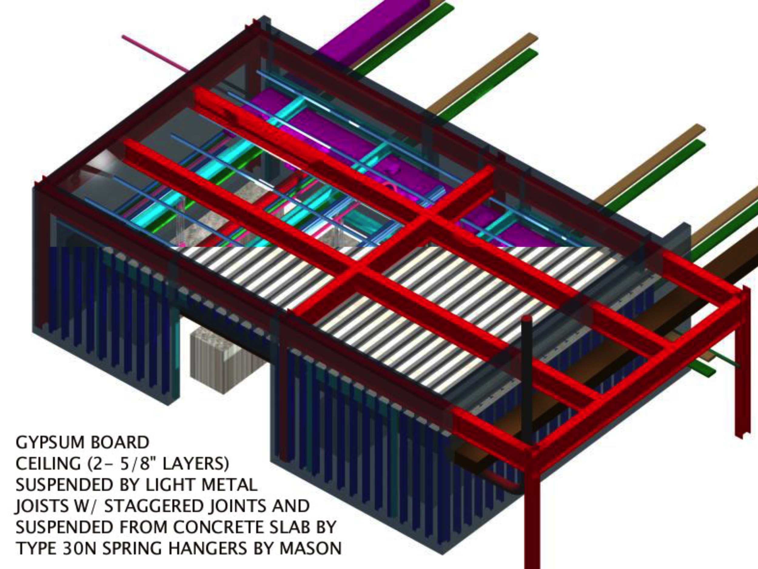
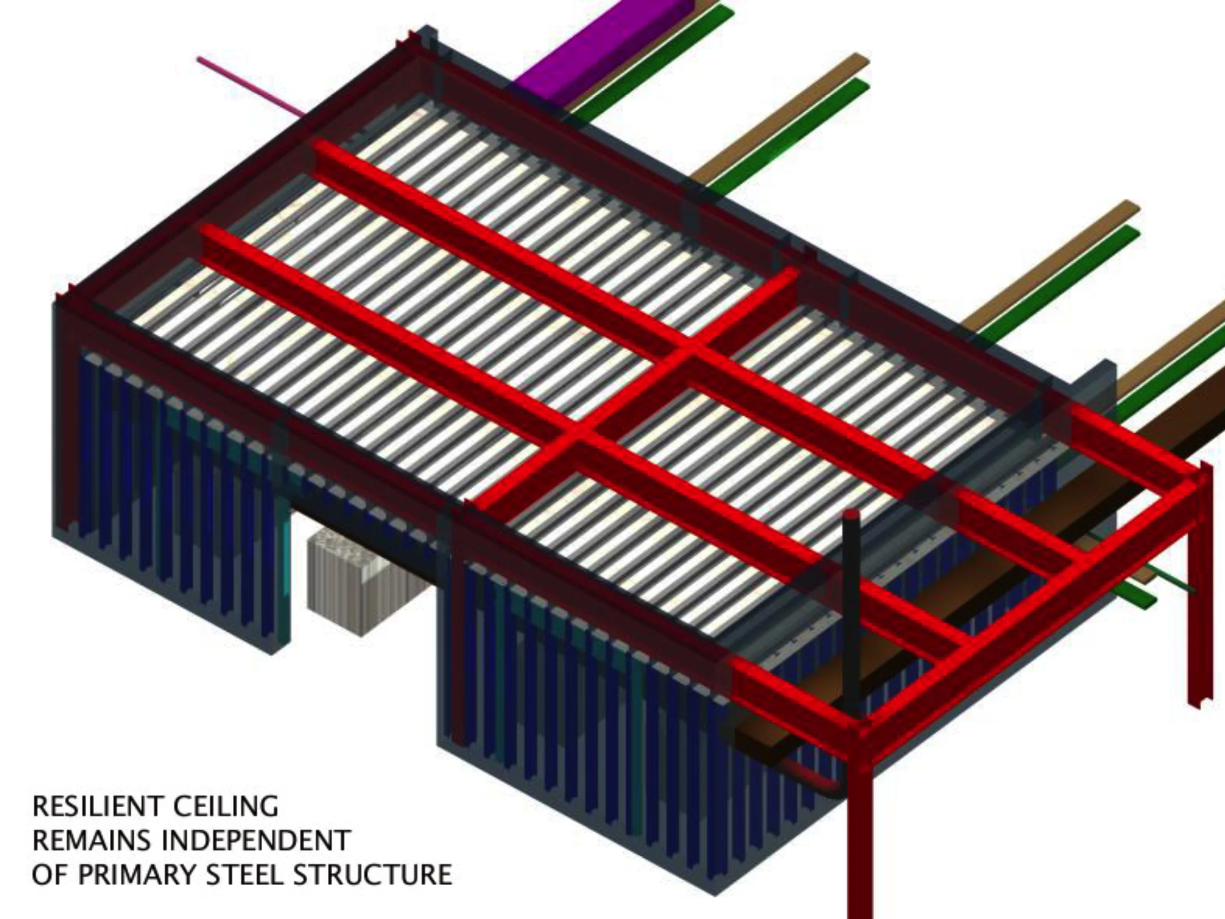
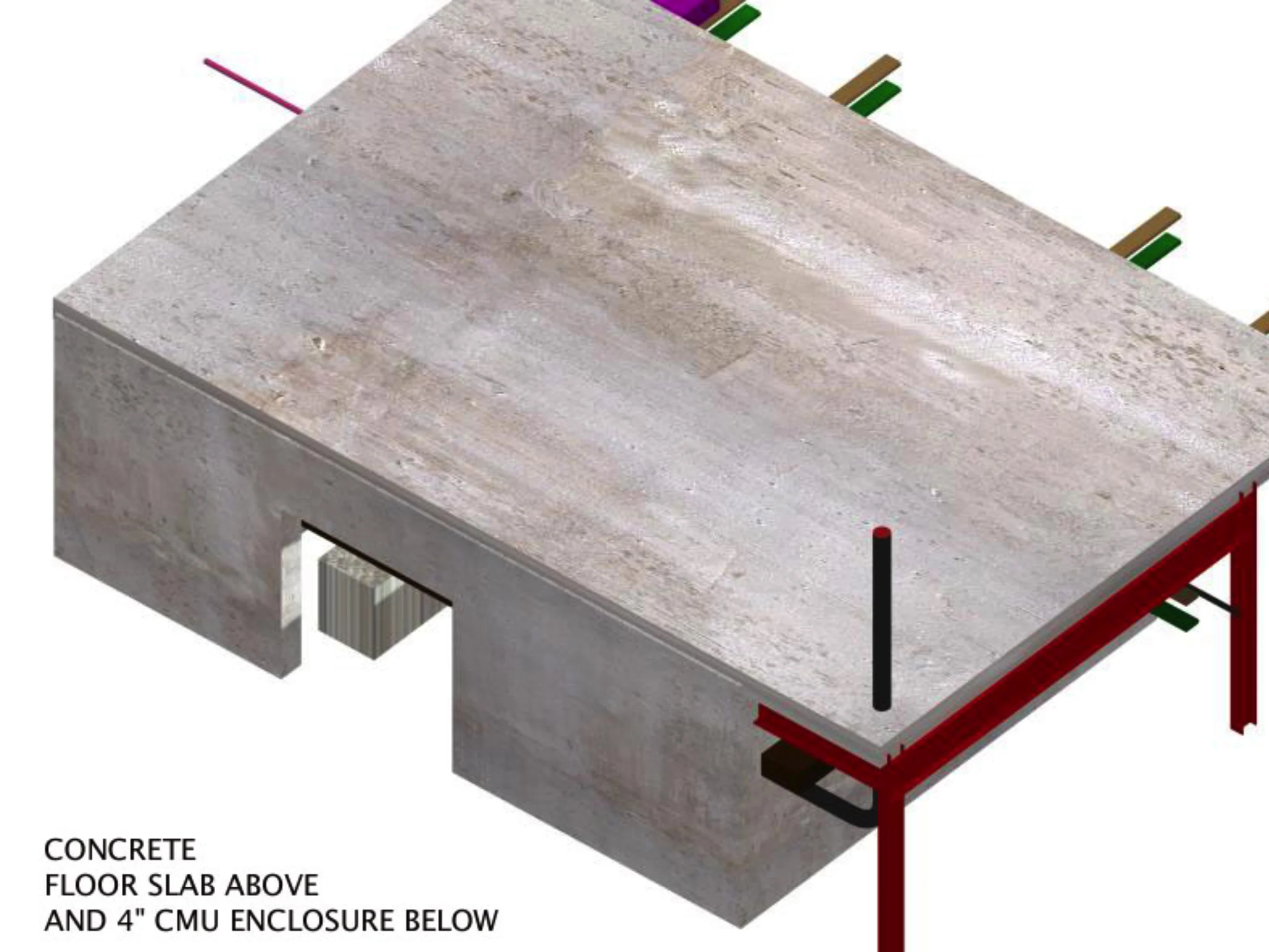
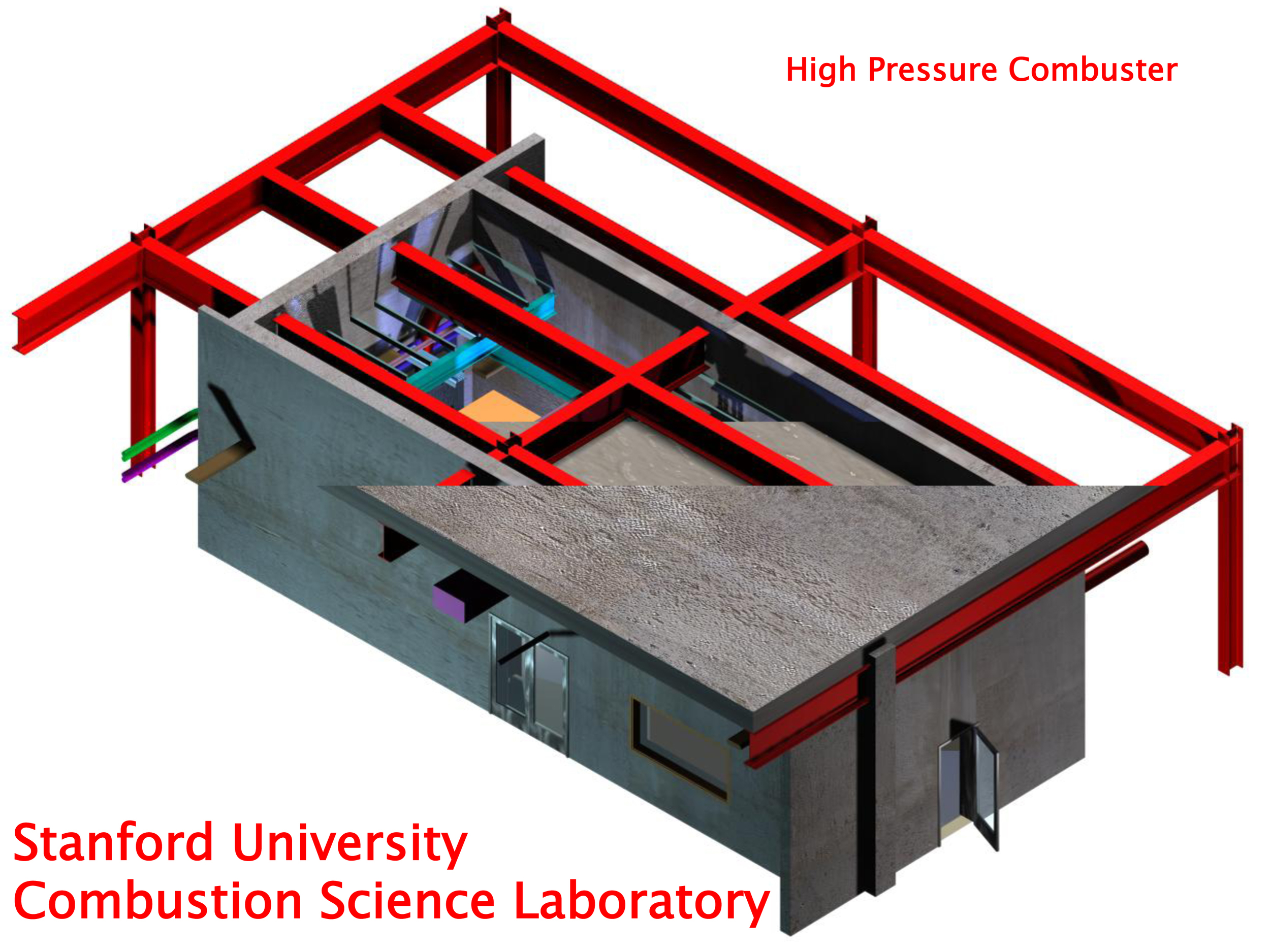
The type of research carried out in this laboratory:
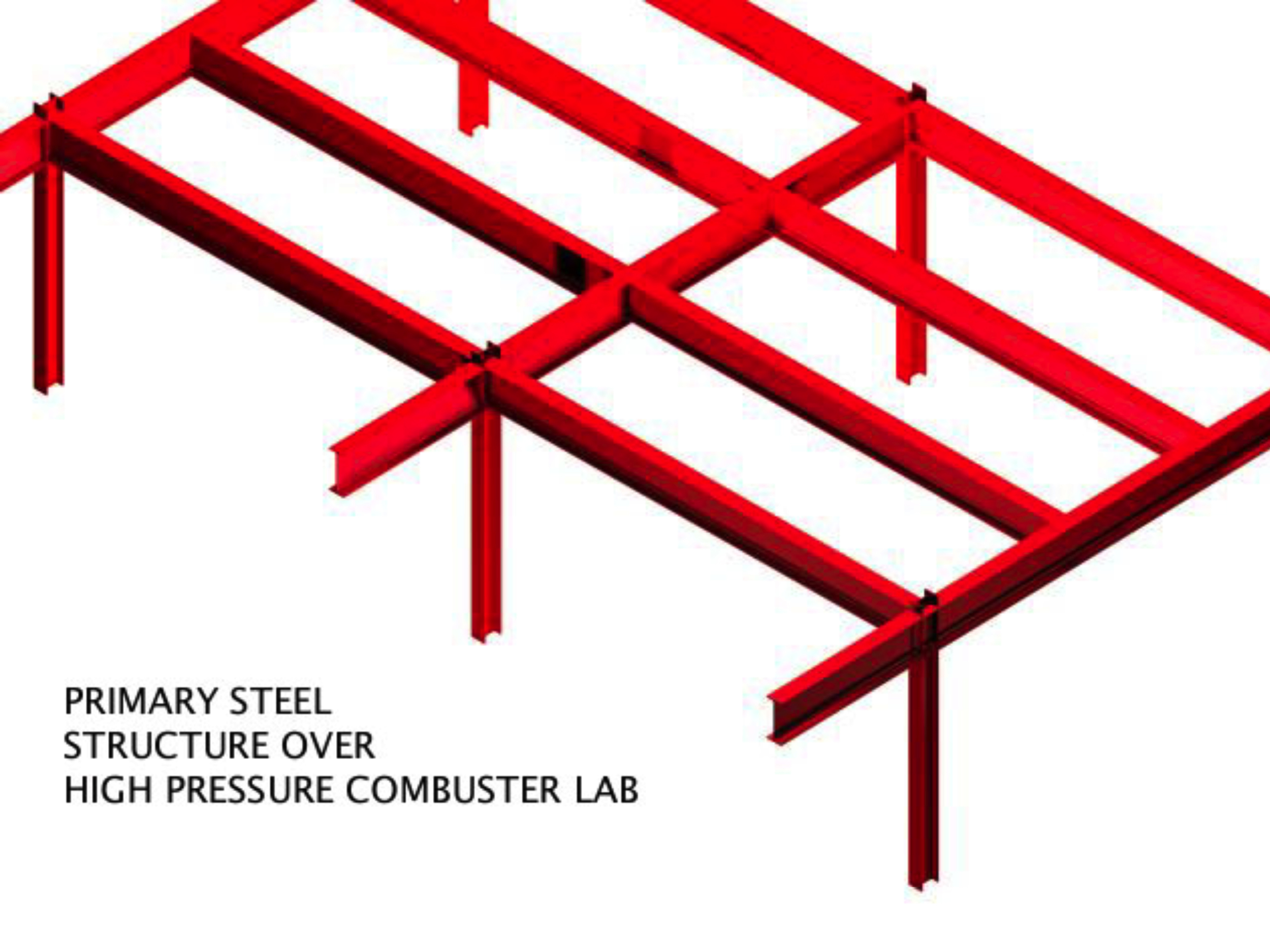
Prevent experimental explosive vibration detonated in this lab from reaching this steel frame and telegraphing noise to the entire building.
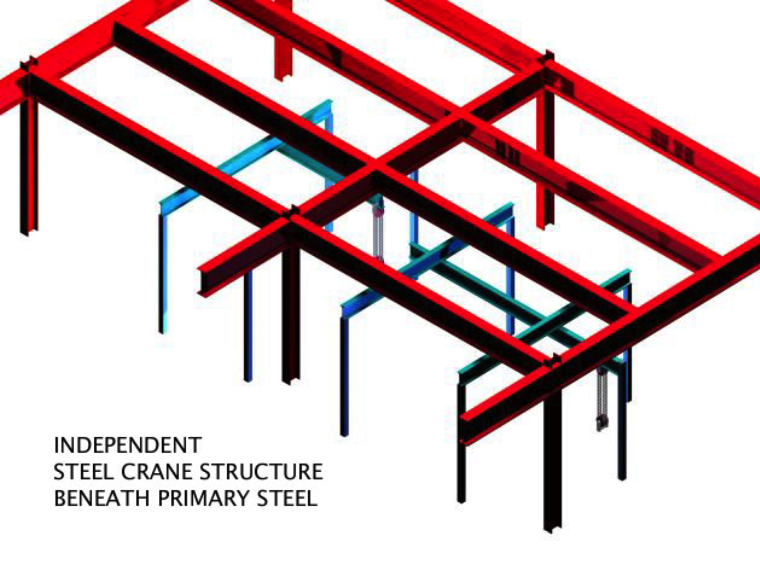
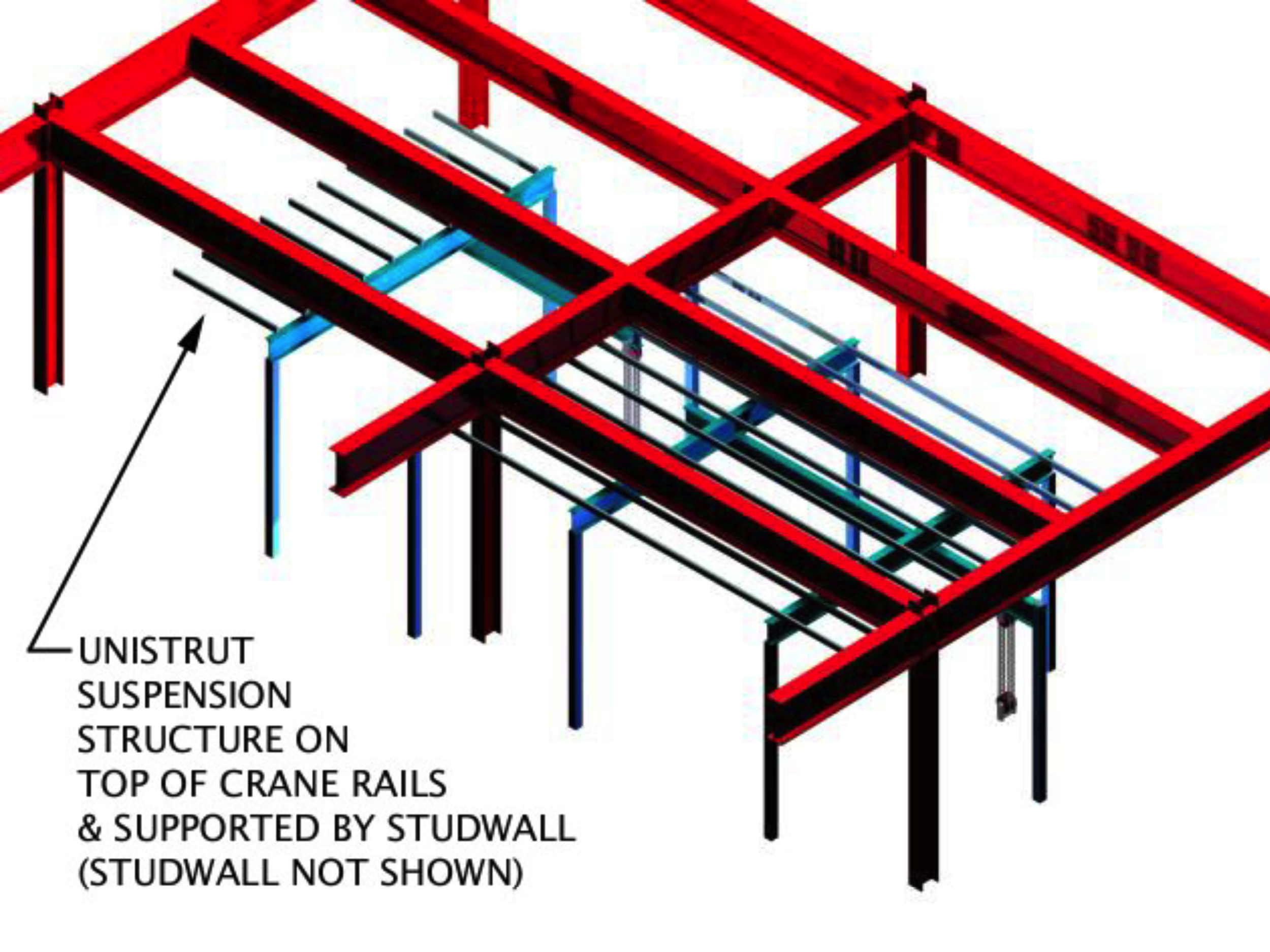
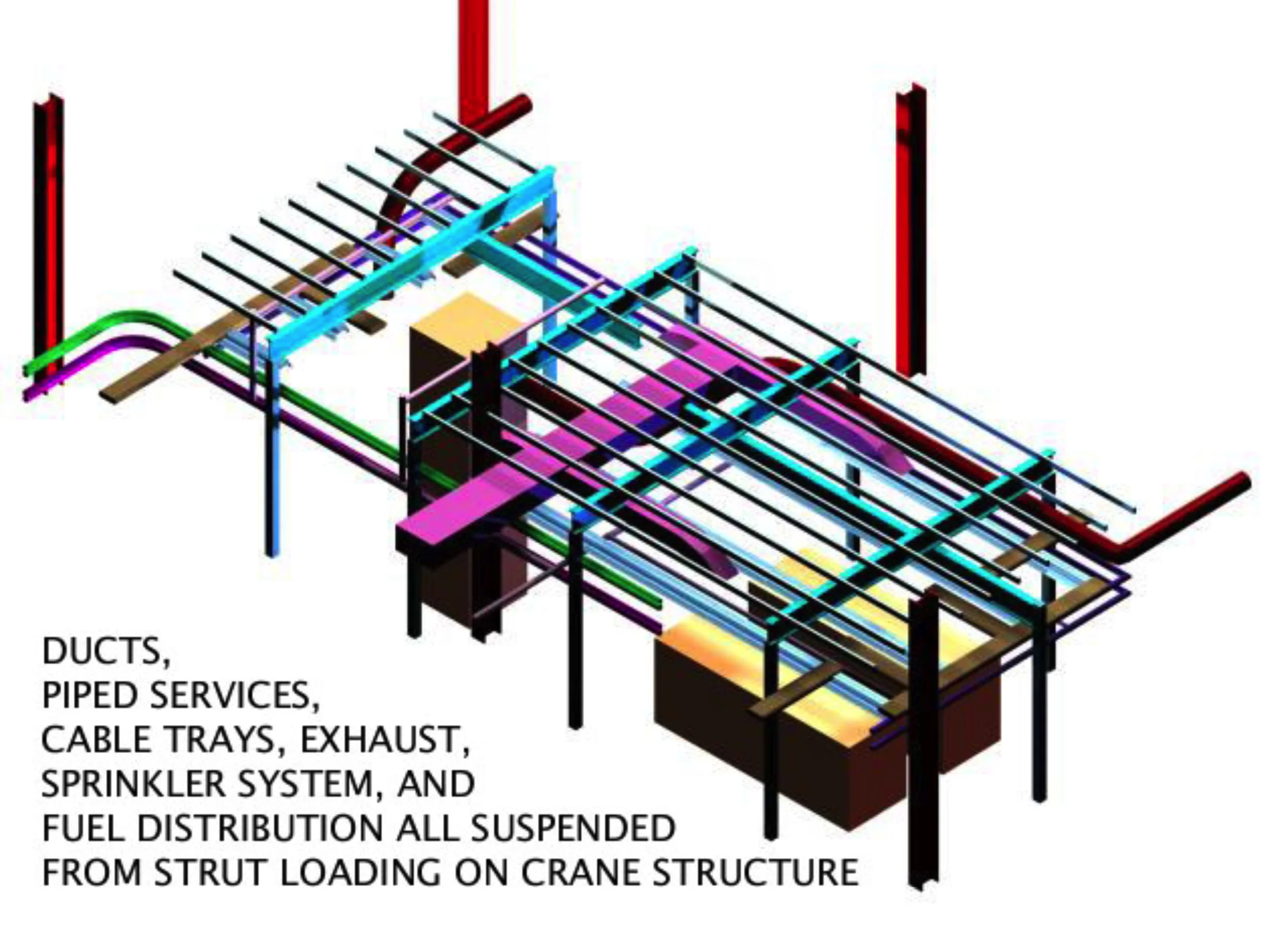
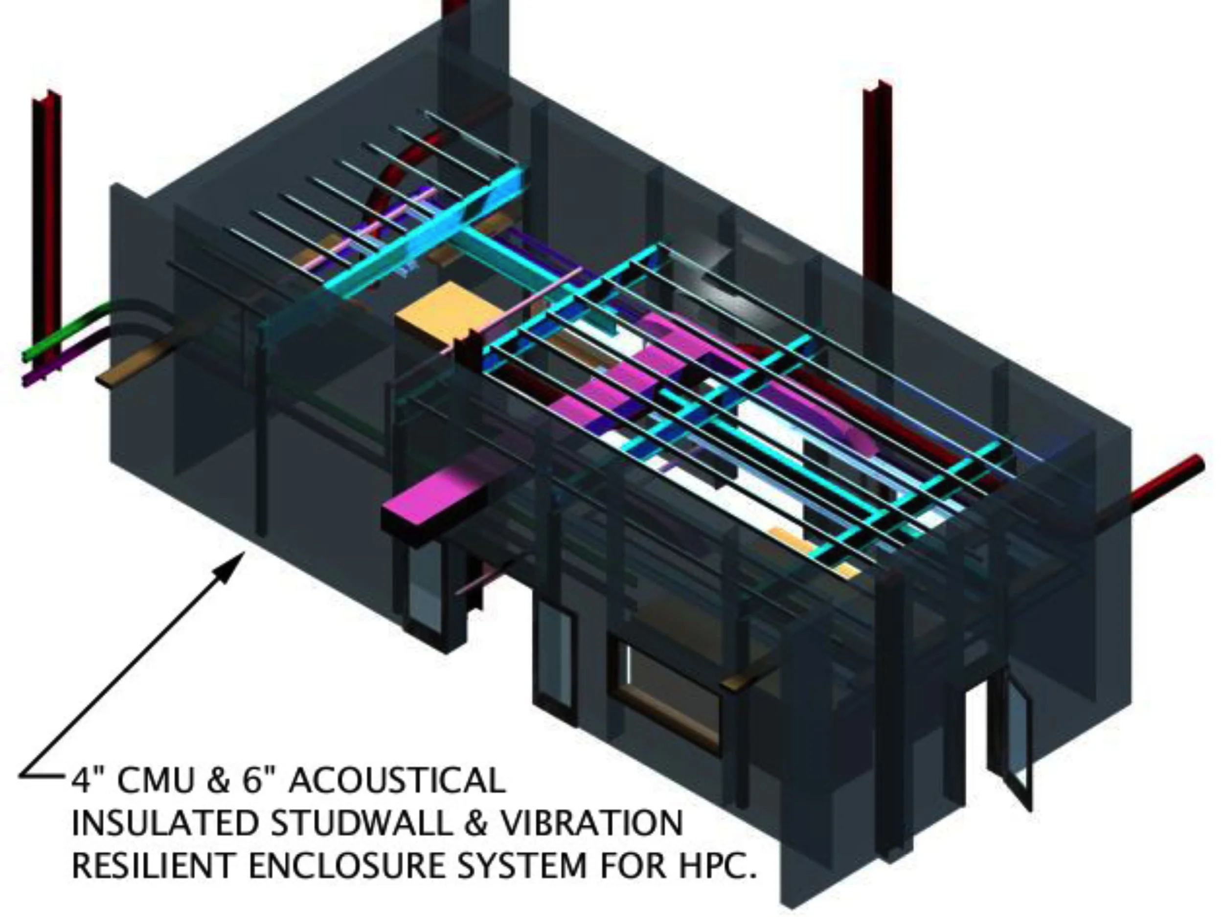
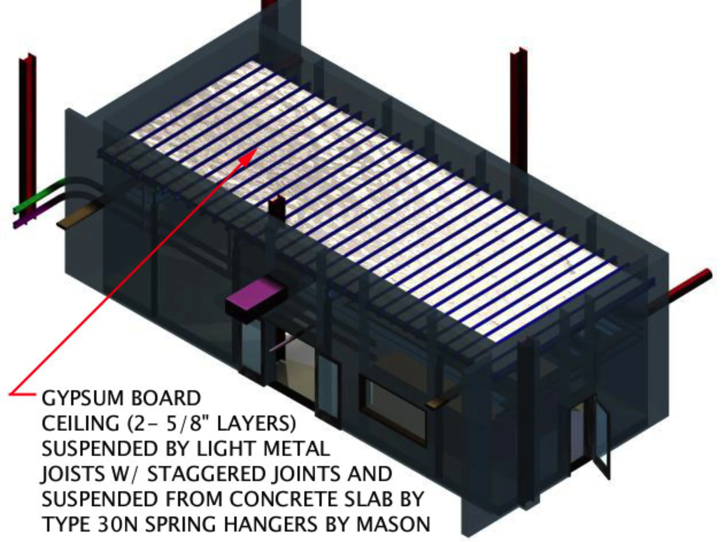
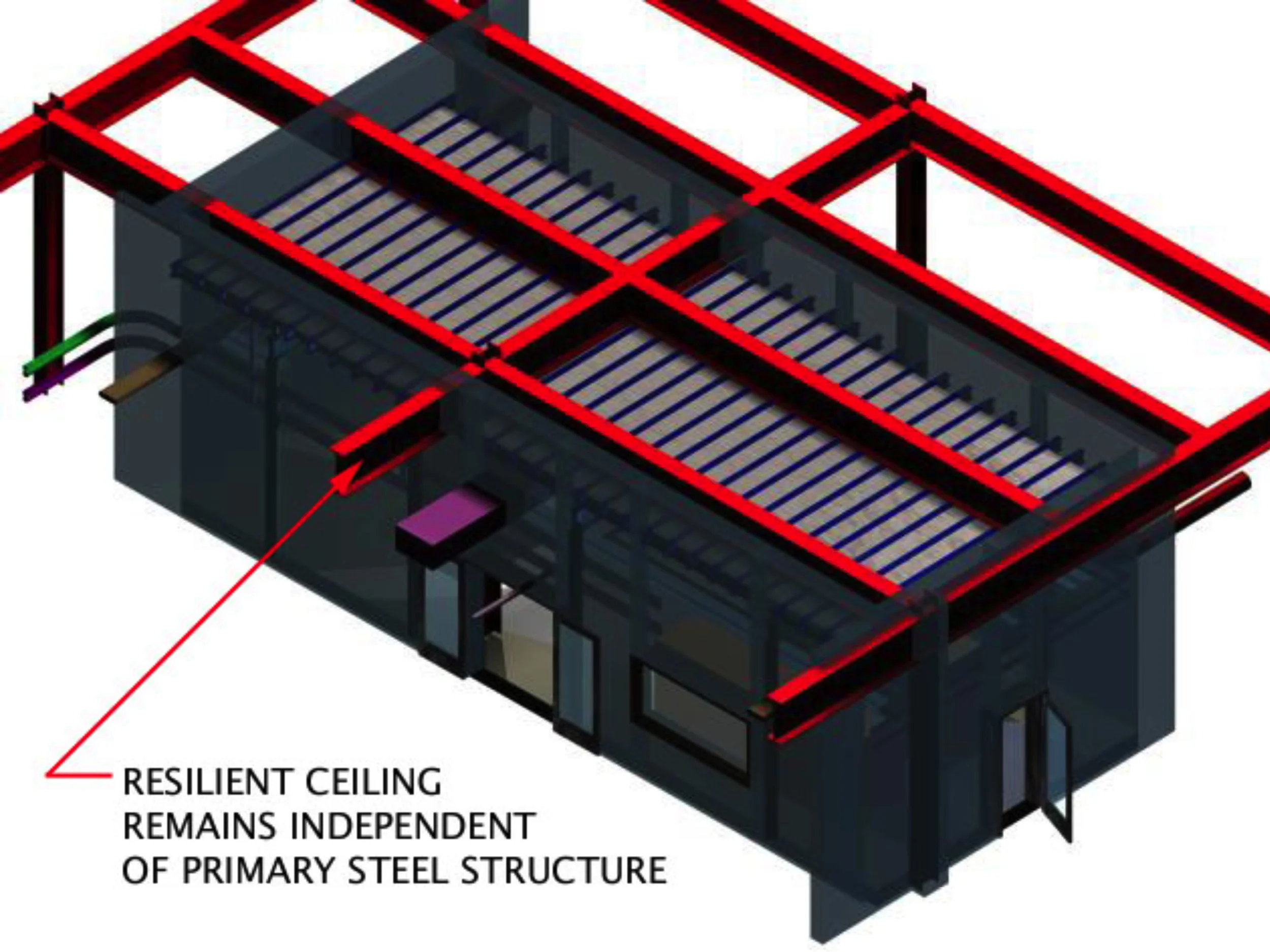
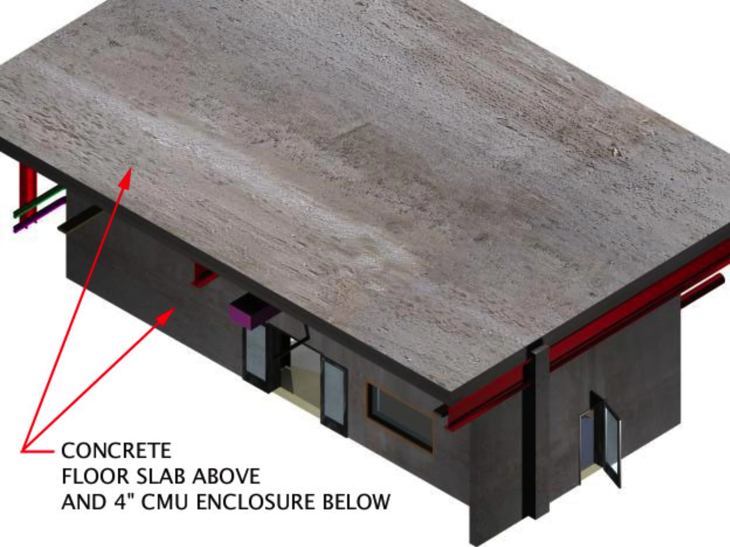
Stanford M.E. Lab DD
Project Summary:
Architecture Firm: MBT Architecture, Seattle
Client: Stanford University, College of Mechanical Engineering
Date of Construction Completion: 2001
John Millard's Role: Project Architect for Combustion Science Laboratories (High Pressure Combuster Lab & Engine Laboratory)
Duration of Design Effort: Schematic Design- November 1999, Design Development- May 2000, Construction Documentation- October 2000
In a laboratory environment, the coordination of equipment, casework, services distribution and penetrations with the layout & fabric of the building has always required the focused effort of MBT lab architects. With improvements in computer processing speed we are now able to carry out our work three dimensionally from conception to construction and now have systems in place in our Seattle & San Francisco Offices to communicate the following enhancements to our workflow.
· We are now able to hand over electronic 3d files which offer a post-construction role to facilities management as an object-oriented three dimensional database including all casework, interior partitions, equipment, furniture, and architecturally driven flexible services distribution systems. We collaborate with casework manufacturers, contractors and engineers in the exchange of data to this end. In the event of reconfiguring a lab for new workflow, these files can make this process the electronic equivalent of “rearranging” the lab rather than a total TI redraw.
· The advantage of producing plans, sections and interior elevations of detailed spaces such as a laboratory by cutting through a “3d virtual building” and providing the required information in two dimensions is that changes, once made to the model, are automatically updated in the schematic phase 2d drawings.
· User visualization of spaces and usability of working environments can be a challenge when reviewing two-dimensional plans. MBT offers clients such as Stowers Medical Research the service of viewing space by animation. This is a direct result of having the design developed three dimensionally. Alternatively, users may receive VRML files of their spaces from the web based project site and navigate freely through space using a web browser plug-in.
· By constructing “intelligent” drawings, specification of the building quality can be derived directly from the model and incorporated into the specification, schedules, and inform the cost estimation process more completely.
The status of these drawings is 90% for DD – excluding any detail references, section references, dimensions, wall-mounted fixtures such as those shown on the plan for these spaces, as well as more detailed notes which should probably go on larger scale sections anyway.
Prior to drawing sheets A401, A512, A513, there was an investment of time to carry out the following tasks:
8/6 – 8/9 – Convert 3D models to 2D acad files/ 14.5 hrs
8/3 – 8/4 – Transmit HPC report to consultants via UPS/ 8 hrs
7/28 – 8/2 – Complete the Pagemaker report/ 30 hrs
7/27 – Add additional 3D components to HPC model based on the late user info/ 8 hrs
7/26 – Transmit Engine lab report to all/ 8 hrs
7/15-7/22 – Complete Engine lab Pagemaker report/ 30 hrs
6/28-7/14 – Construct Combustor model/ 53 hrs
6/14-6/25 – Construct Engine Room model/ 57 hrs
Status of this work is the
· AH 3-D models are pre-user conf 8/19
· Mounting heights shown for HPC on sheet A401 are subject to Gaynor Engineers (or someone else’s) correction of mechanical scheme. Defects of currently show design—
· All supply air ducts conflict with crane structure.
· Return air duct conflicts with cable trays and power feeds and piped services.
· Penetrations through fire-rated west wall create unnecessary acoustical and fire damper conditions and excessive duct length – Access to HPC Lab with mechanical ducts should be through north wall over the door as shown in report transmitted to Gaynor on 8/4.
· HPC self-aspirating exhaust pipe conflicts with travelling bridge beam (again ignoring 8/4 report recommendations as well as telephone conversation with Grant Wong on 7/7/99.
· HPC s-a-e-p also breaches 1 hour fire wall (twice) on west side of occupancy separation.
· In general, there are far too many F.R. penetrations.
· I have not yet received a set showing other services…will they be showing all services described in my report? If not, who will be showing them at C.D. stage?
· Users need to by off on cable tray clearance shown in 2/A513 where they throat down to penetrate control room wall.
· The above penetration conflicts with display panels in control room (see 1/A513). We need direction on how to resolve this conflict.
· Brian Carilli suggested moving the sprinkler pipe above the exhaust pipe at the 8/18 meeting. Done. But as shown in 3/A513, stub ends may still be necessary to clear obstruction of exhaust pipe per code.
· Fish eye diffusers in F. R. ducts and HPC ducts should be specified to provide effective air.
· Wall-mounted outlets, etc., which are shown on plan may be drawn on int elevs for clarity but will be replicated and all other outlet info. Missing from other in t elevs.
· Section indicators should be drawn on plans and sections.
· ½” sections (partial) should be drawn through complex cond.
· Details including bracketry, acoustical penetrations, seismic, drywall connections to unistrut, miscellaneous metal, window and door details will all be necessary in thse spaces – Control Rooms will require additional detailing for equipment mounting, combustible gas penetrations as well as others.

The New Stanford University Mechanical Engineering Building by MBT Architecture is a two story concrete structure that required a team of six architects at MBT to participate in the design and documentation. John Millard was responsible for the shaded area on the first floor plan known as the Combustion Science Laboratories. John travelled frequently to Stanford to meet with Stanford Professors involved with the programming, equipment requirements and the ergonomic considerations of the client team.
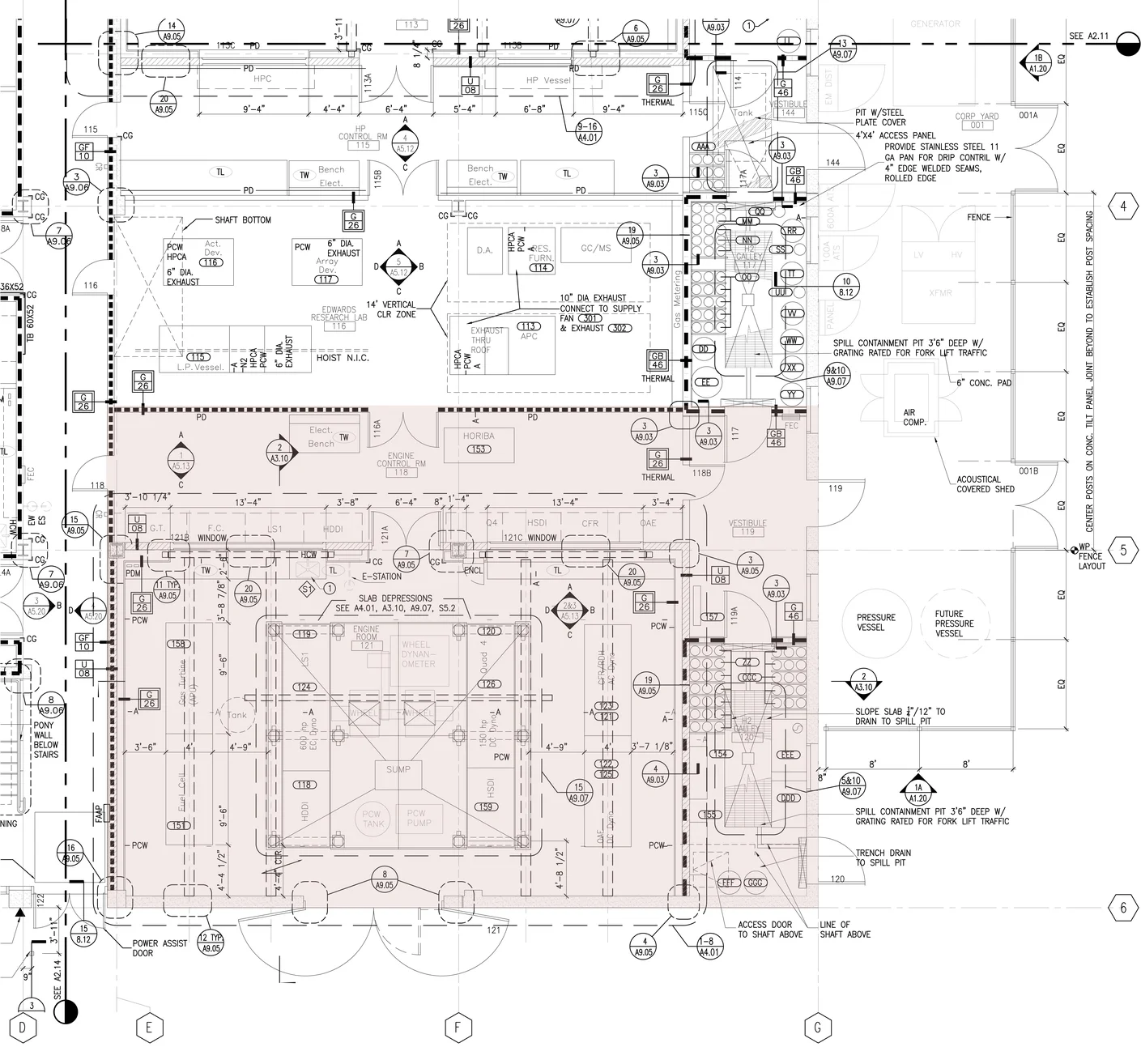
The Engine Lab and its associated control room in the College of Mechanical Engineering are shown shaded in the plan above. To the right shaded area is the Hazardous Substances Gallery where various combustible gasses and liquids triggered fire code requirements that John Millard was also responsible for conferencing with the AHJ in Palo Alto, California.
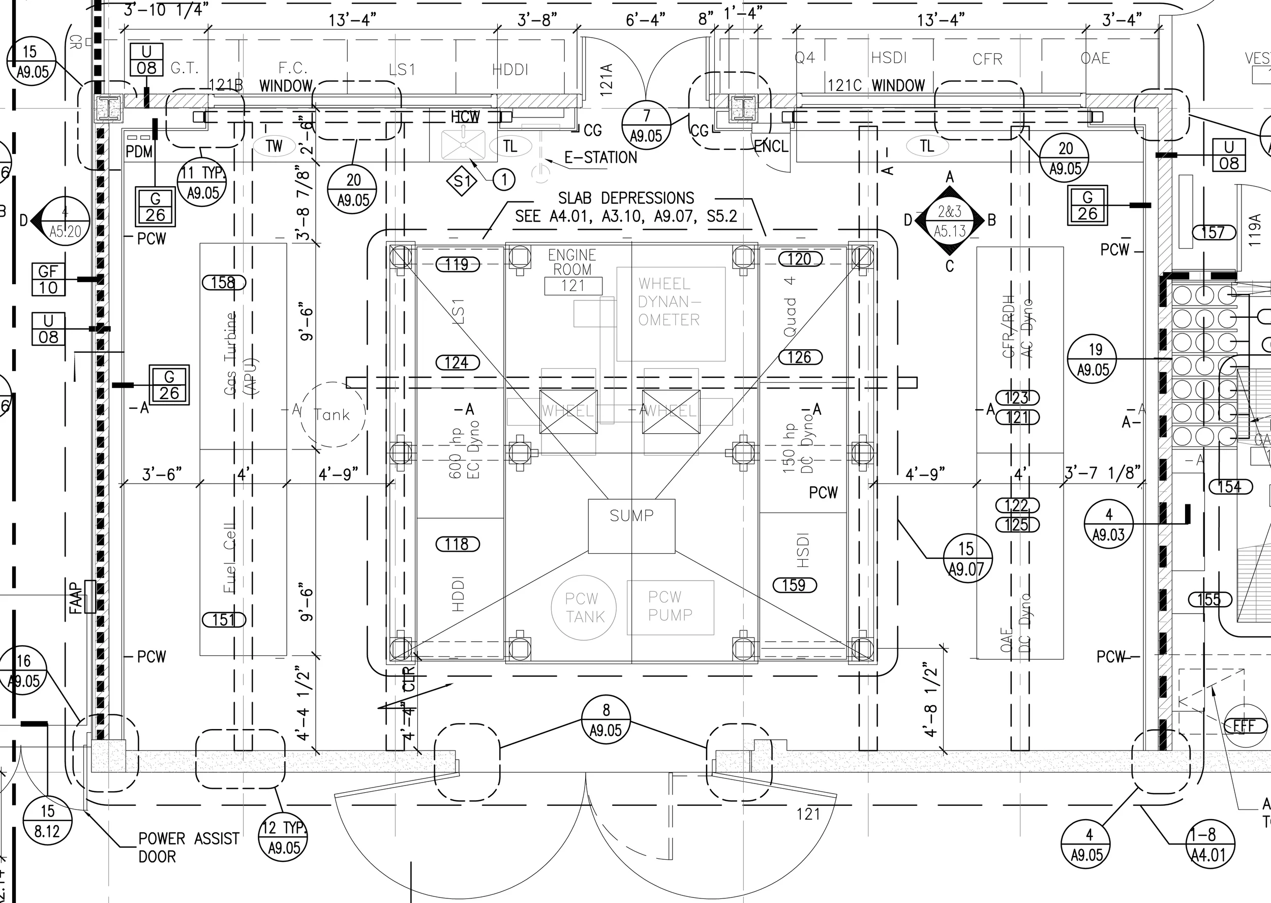
By far, the most noise produced by research activity in the building is in the Engine Laboratory where both sound from combustion engines and vibration from entire road vehicles atop the dynamometer might otherwise be transferred into the rest of the building spaces were it not for the acoustical engineering design of Acoustic and Vibration Solutions.

Design Development of the Engine Lab required an architect to unify and coordinate the requirements of each engineering discipline for the space to be constructible. This required the cooperation of the Structural, Mechanical, Electrical, Acoustical, Plumbing, Illumination, and Code Compliance teams to agree on the single mddl produced by John Millard in order to coordinate each discipline's component contribution to the whole design. Forward coordination with the mechanical electrical contractor also was helpful.

The Engine Lab required a plethora of overhead services in order to meet the requirements of the faculty at Stanford's College of Mechanical Engineering. These overhead services were challenged by the requirement of 3 traveling bridge beam cranes that move across the entire work area.

Electrical and Mechanical Contractors often experience coordination conflicts on projects where the architect failed to coordinate the engineering designs. These conflicts can often drive up the cost of construction and lower the confidence in a set of drawings. In this case, the complexity of the layers of overhead services including diesel lines, high octane gasoline lines, hydrogen lines, exhaust air, supply air, power and communications, as well as sprinklers, dedicated exhaust, process chilled water, and lighting- all attracted the undivided attention of the contractor to the architect's coordination drawings for this lab, and they were not disappointed.

In this section, the slab depressions required to contain (from left to right) a) the possible future sprinkler water in the hazardous substance galley, and b) the dynamometer for vehicular movement management- both show a depression in the floor slab that headed the list of slab depressions in the entire building that were coordinated by John Millard.

This interior elevation shows penetrations in the acoustical envelope of the room for the traveling bridge beam crane rails, control room windows and other openings that risked transference of noise into the lecture spaces and labs on the second floor. The detailing of these penetrations greatly reduced the noise.
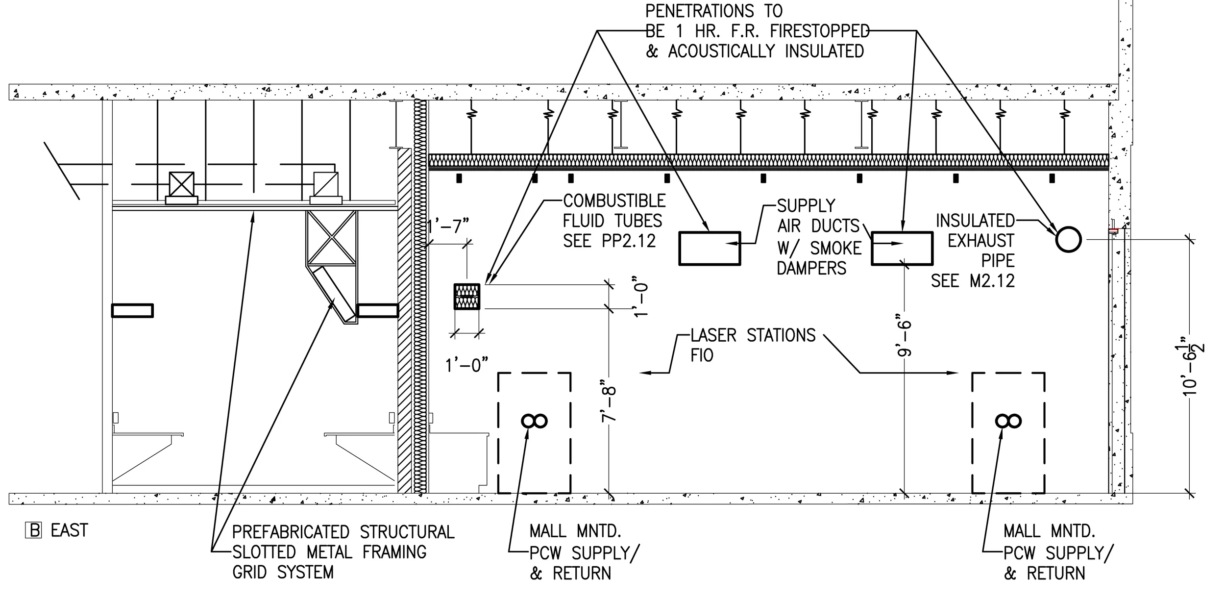
Each wall penetration had both acoustical and fire insulation requirements in order to maintain the fire/ occupancy separation that enabled the engine lab to be permitted to be constructed. These protective measures that stop the spread of fire, smoke and noise. This elevation also indicates the plumbing services that exist inside the wall as well as other components that with penetrated the wall or were mounted on the wall.
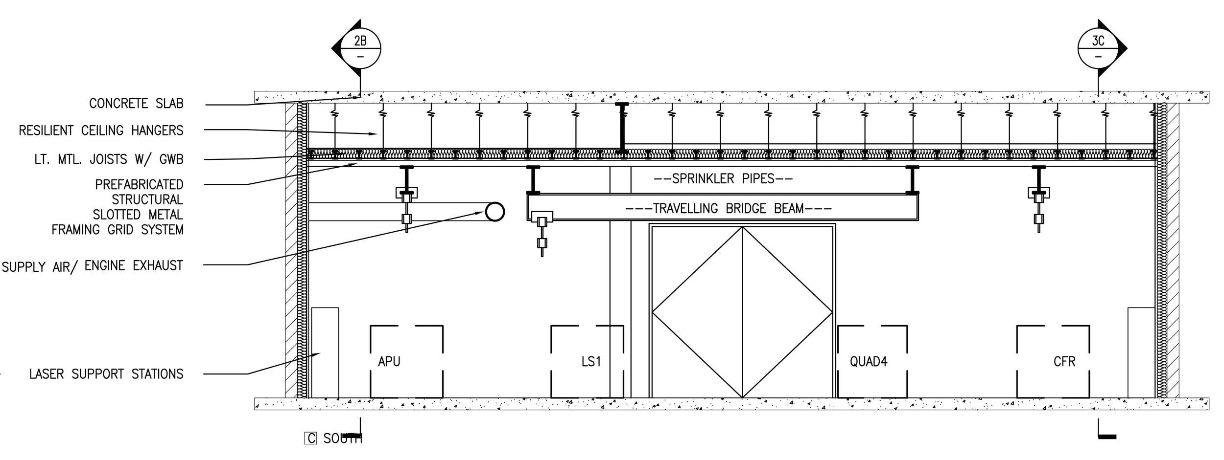
The traveling bridge beam that traverses the center of the room is designed to carry heavy loads such as engine blocks over modest distances inside the room from the double cargo doors in the south wall where a vehicle may access the room and deliver an engine for testing inside the engine lab. The presence of this crane, as well as the linear cranes flanking the traveling bridge beam dramatically reduced the availability of overhead services solutions.
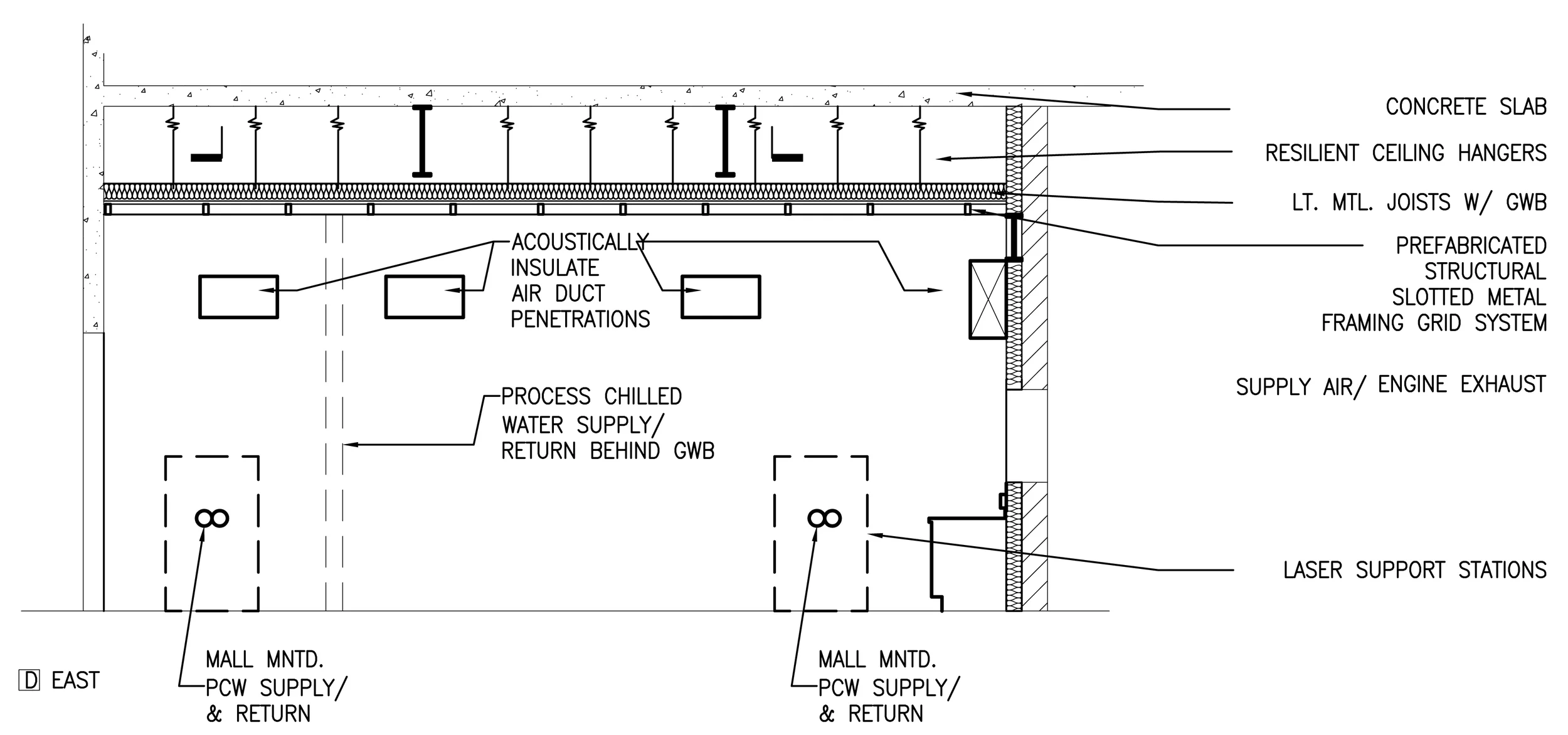
Each wall penetration had both acoustical and fire insulation requirements in order to maintain the fire/ occupancy separation that enabled the engine lab to be permitted to be constructed. These protective measures that stop the spread of fire, smoke and noise. This elevation also indicates the plumbing services that exist inside the wall as well as other components that with penetrated the wall or were mounted on the wall.

This interior elevation shows penetrations in the acoustical envelope of the room for the traveling bridge beam crane rails, control room windows and other openings that risked transference of noise into the lecture spaces and labs on the second floor. The detailing of these penetrations greatly reduced the noise.
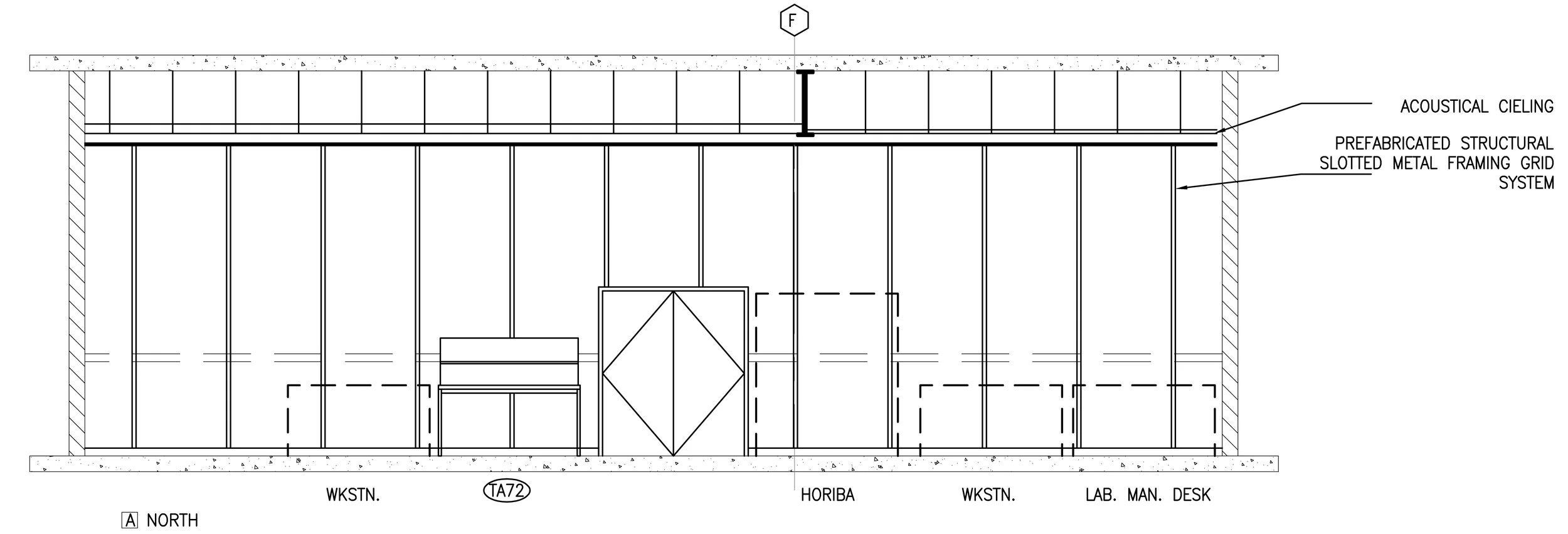
The interior of the engine lab control room was a flexible surface that required intermittent re-organization of user equipment.
Shaded area indicates deign & documentation role and work product by John Millard.




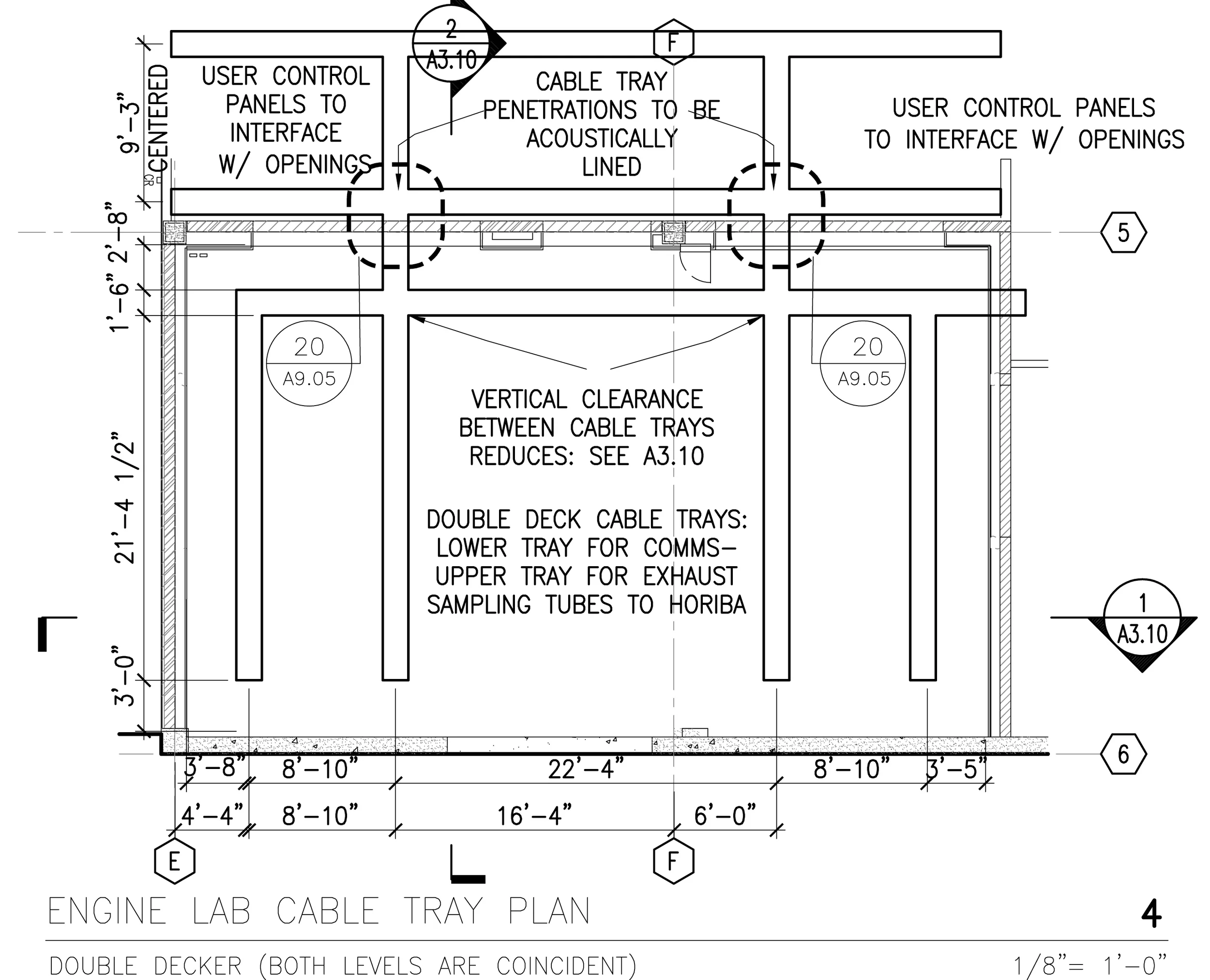

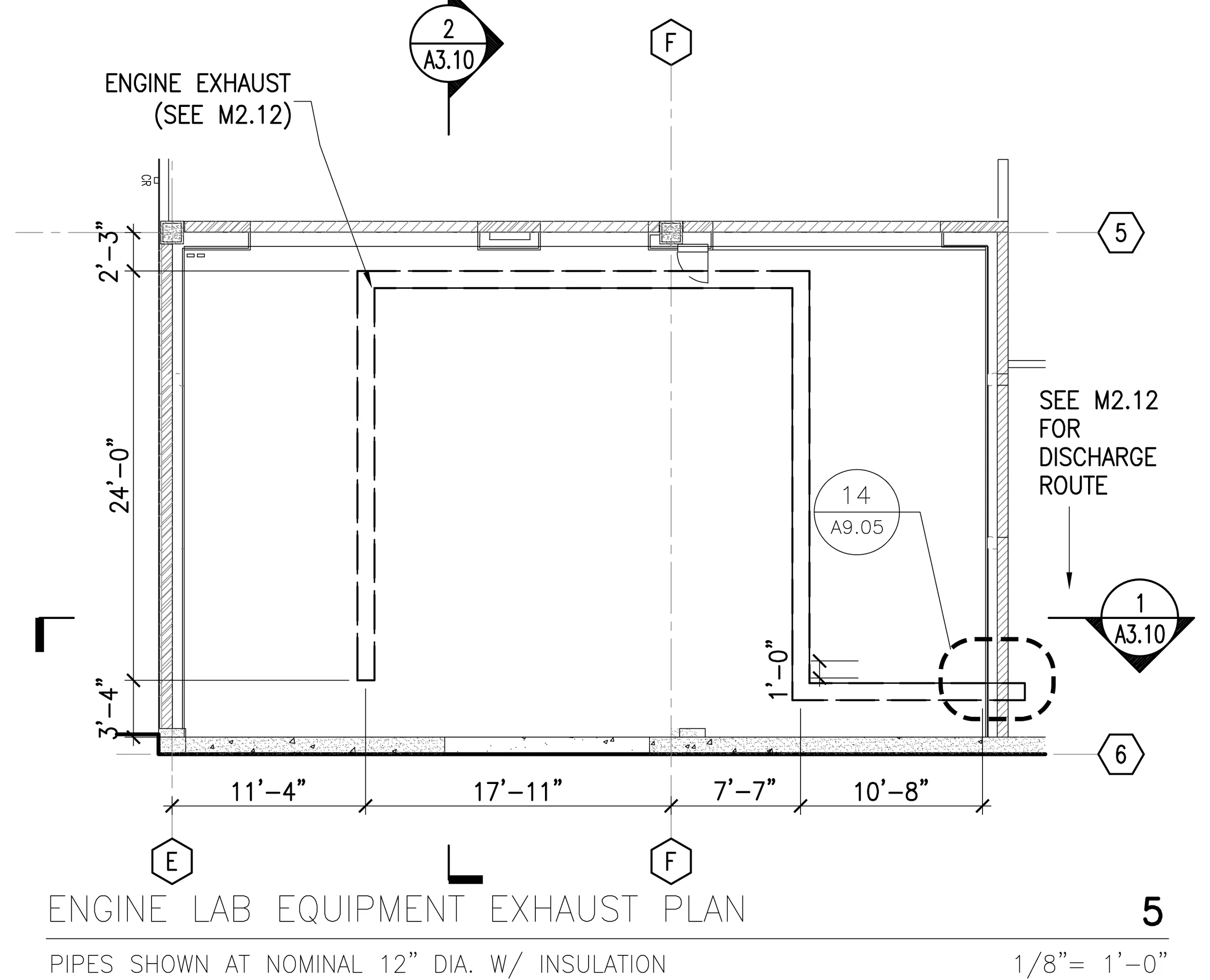



A high-pressure burner is used to study combustion and develop diagnostics under conditions similiar to those in gas turbine engines. A laboratory-scale pulse detonation engine (PDE) is used for the development of laser diagnostics for PDEs. Finally, an expansion tube is used to study supersonic flows.
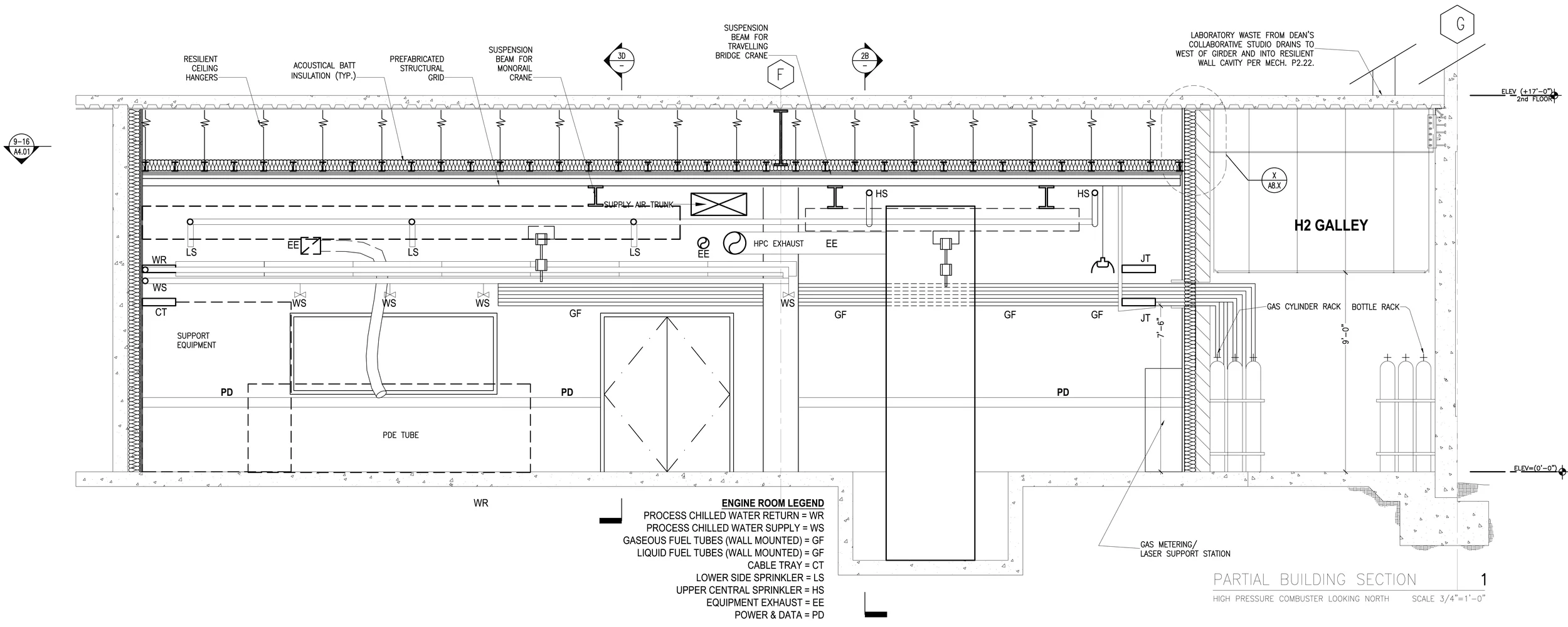
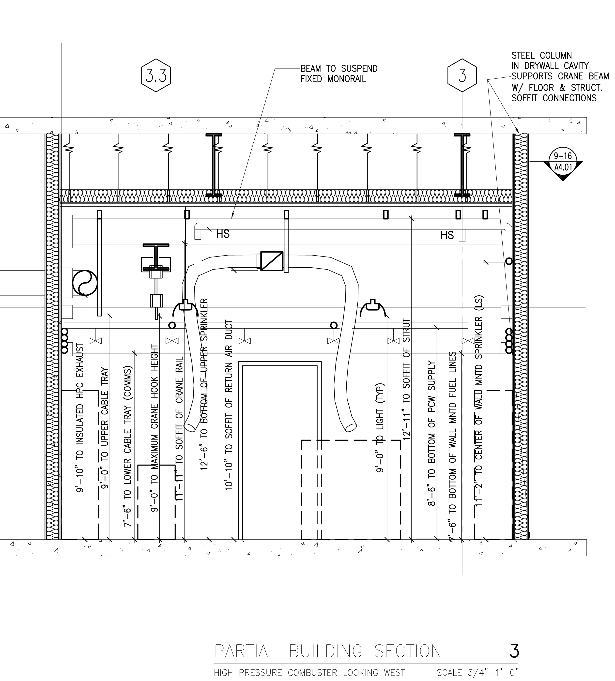


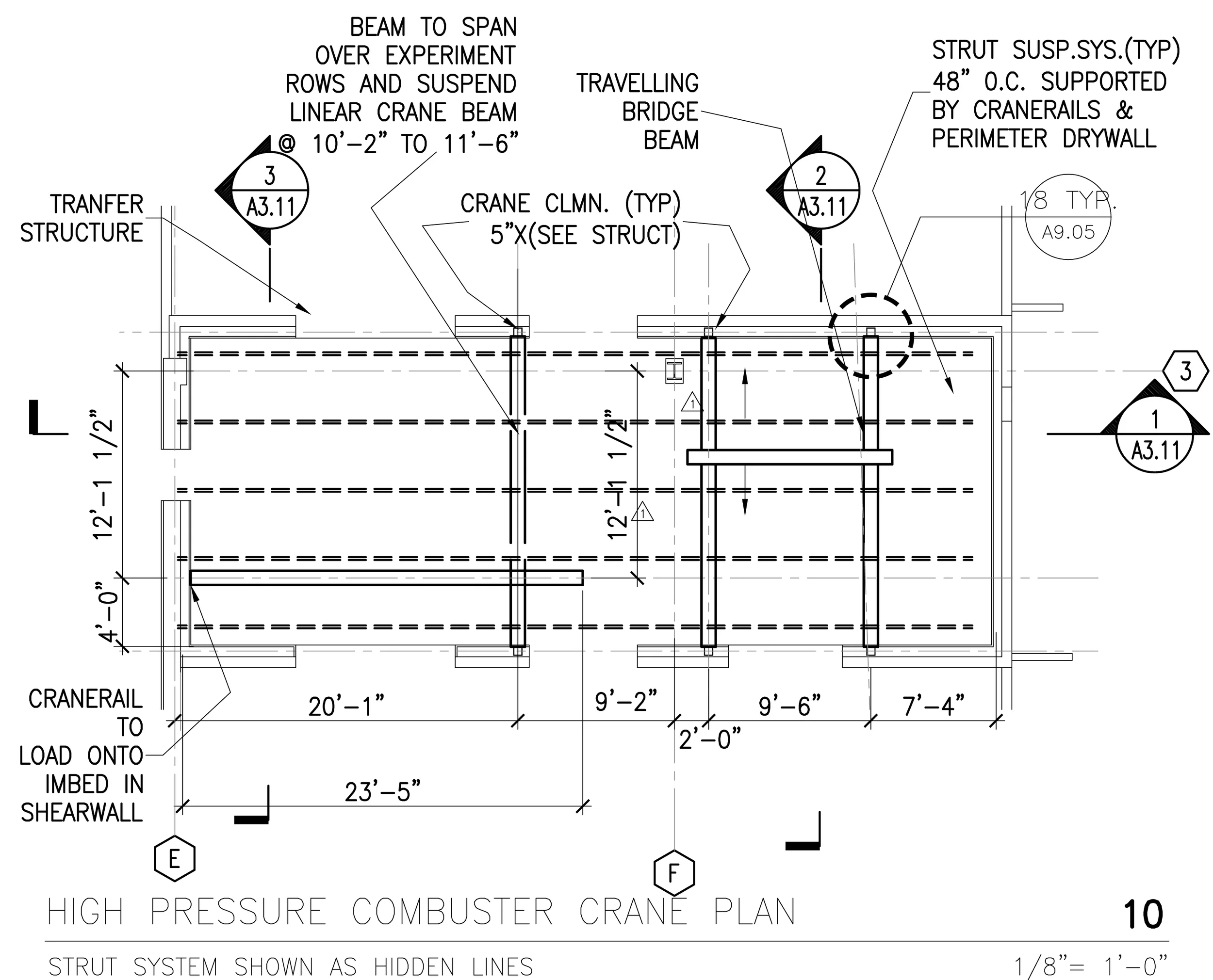


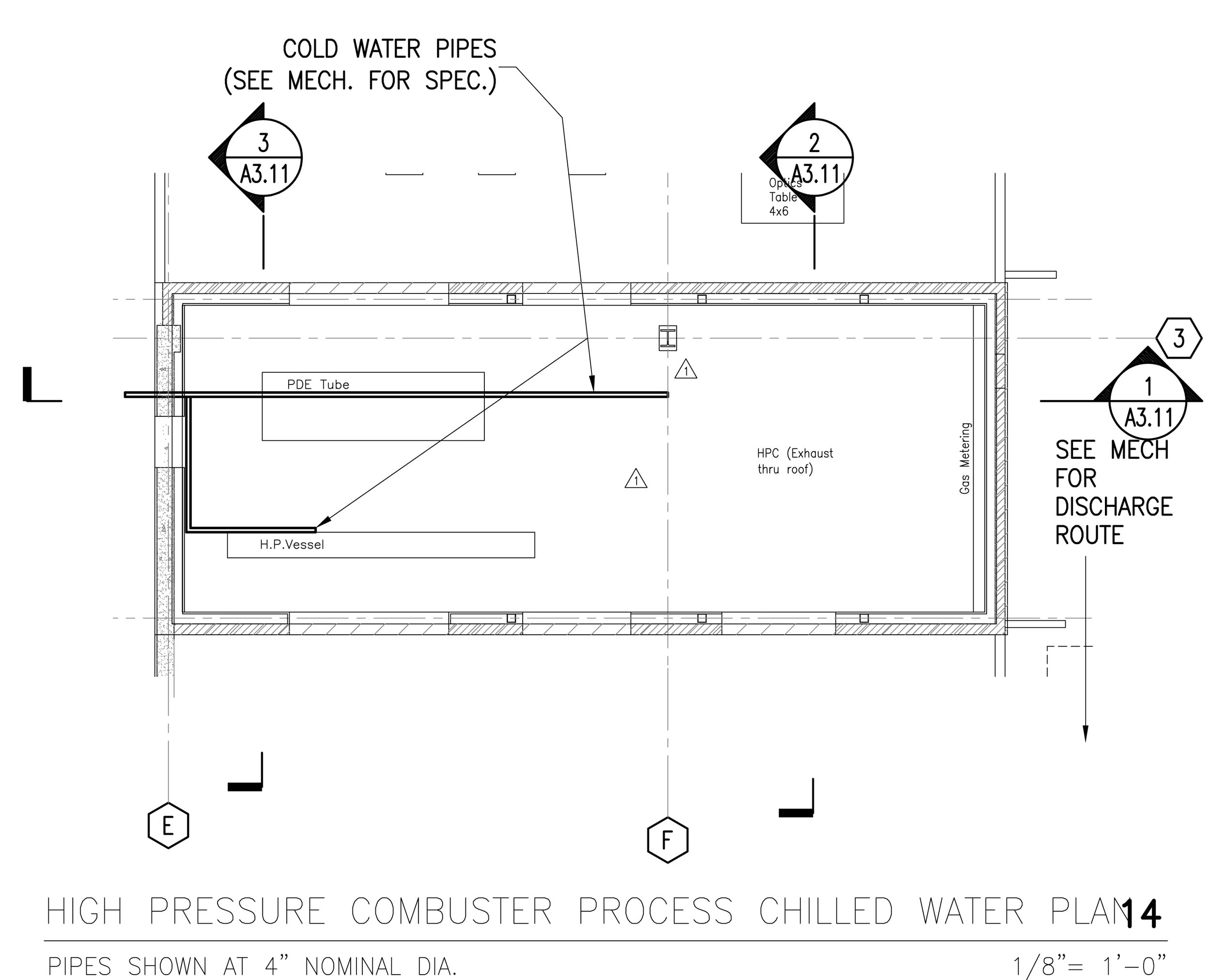

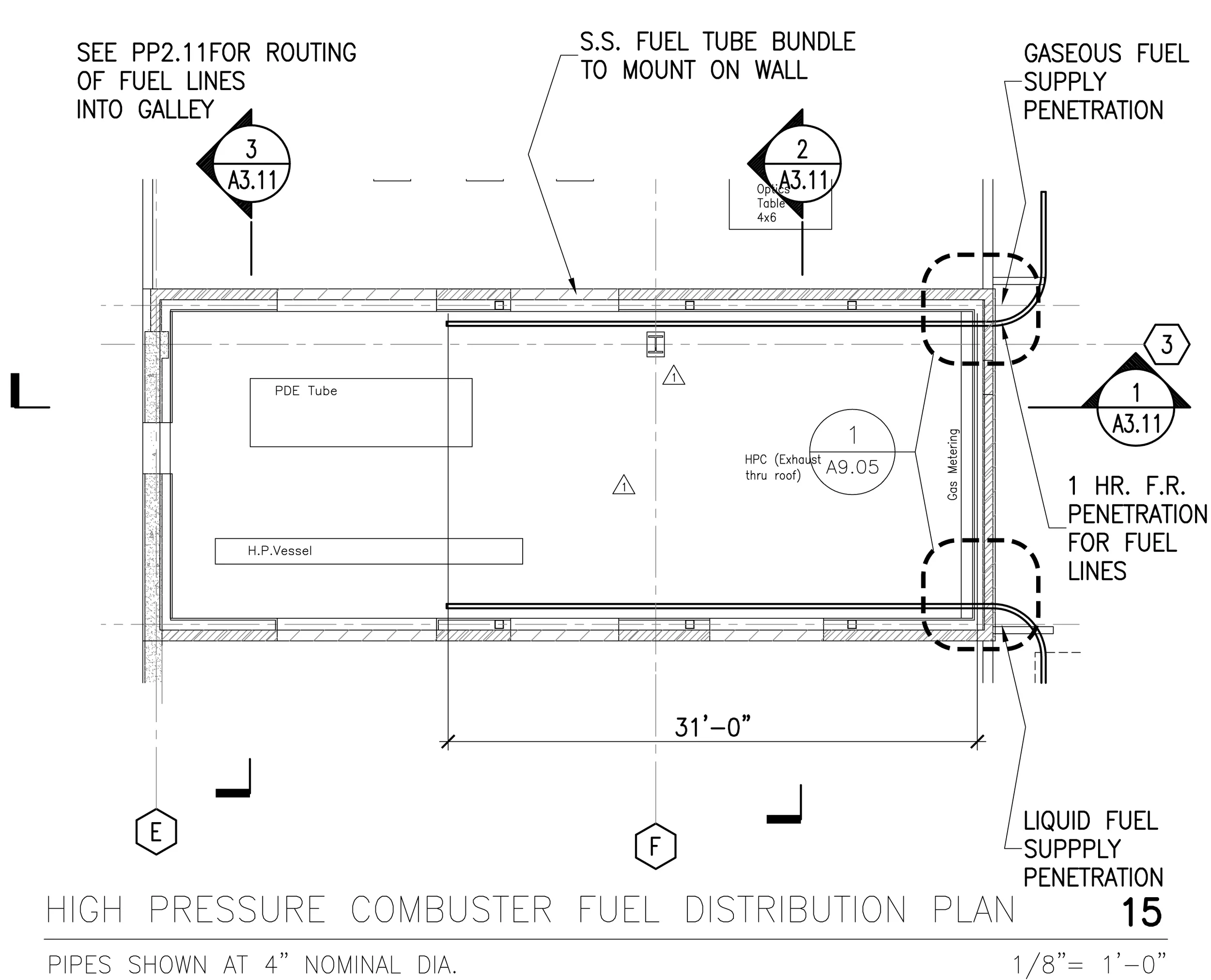

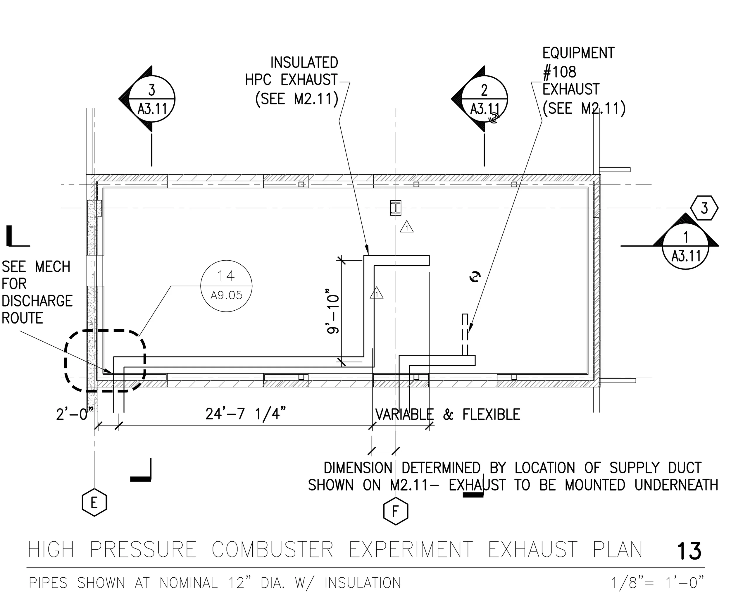

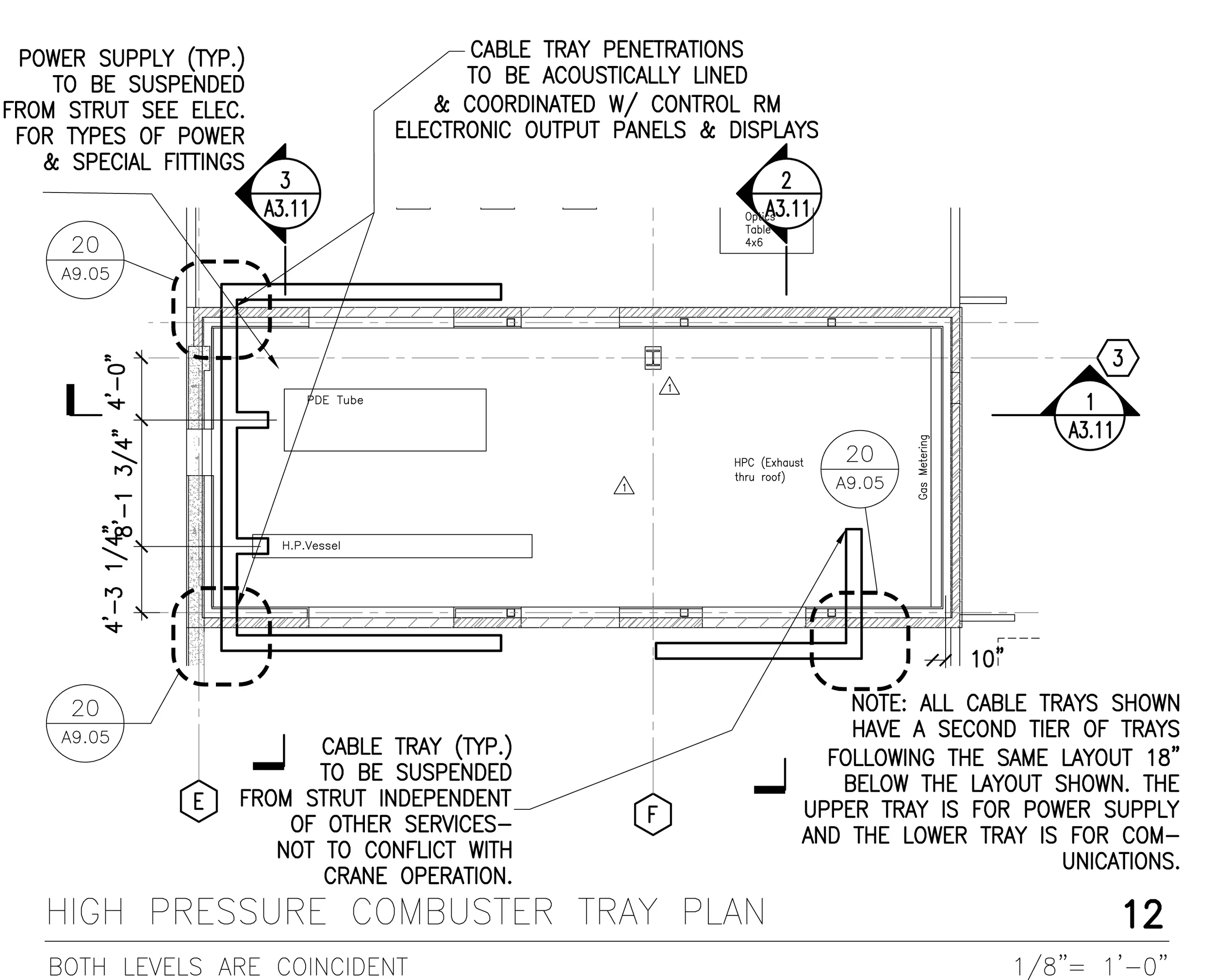


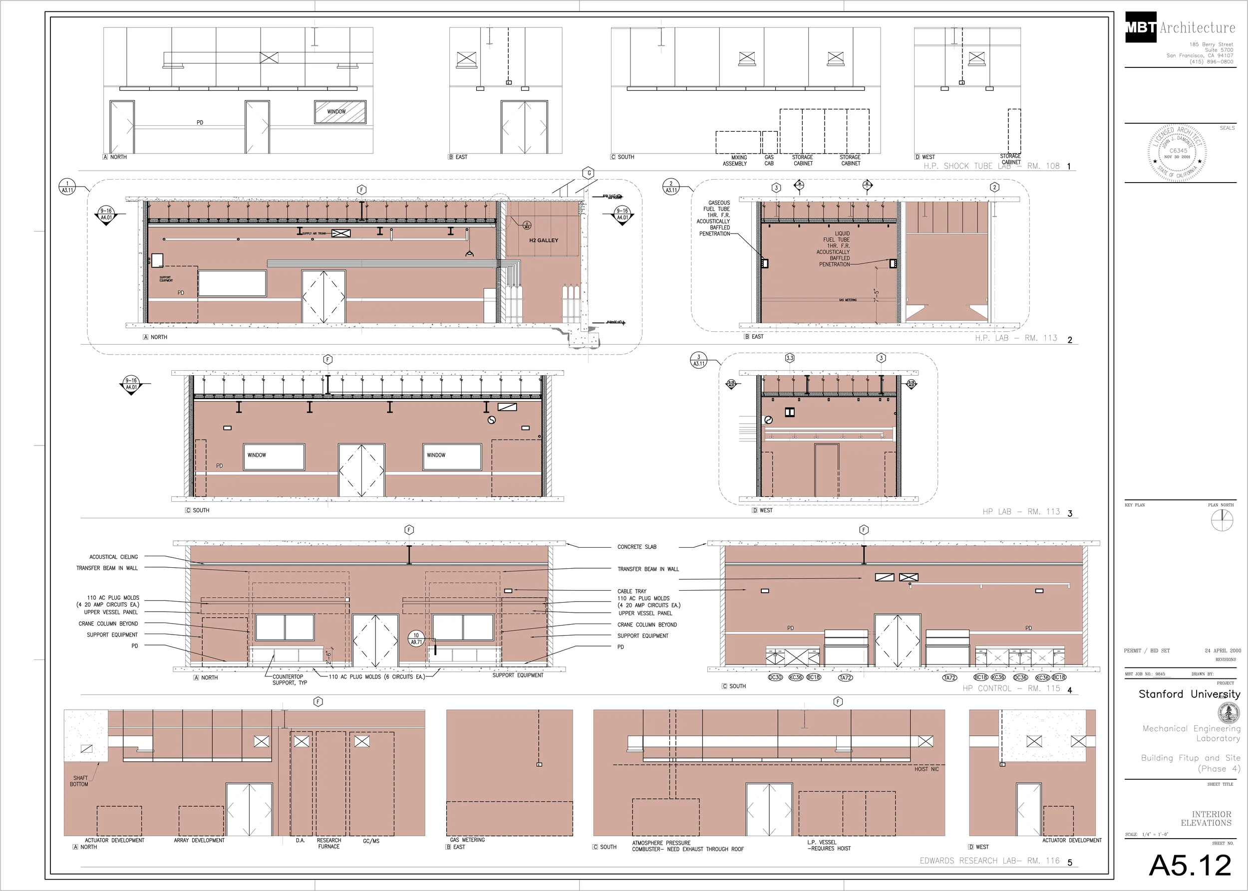
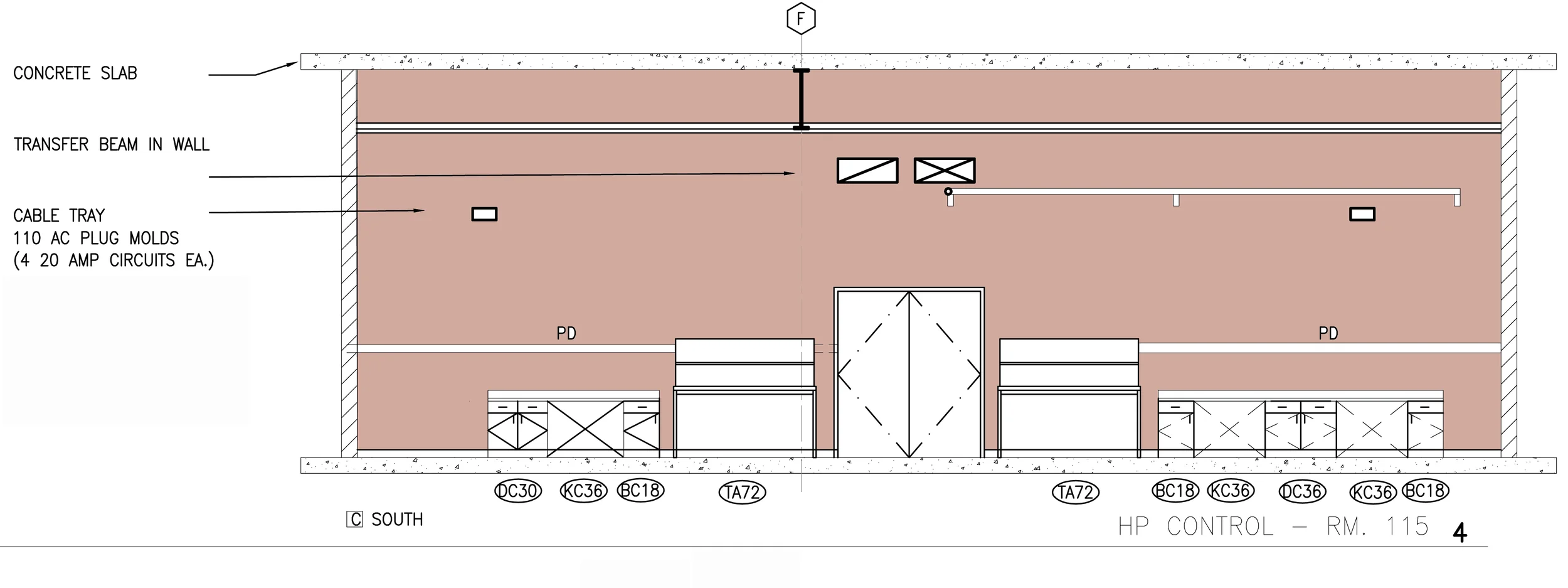
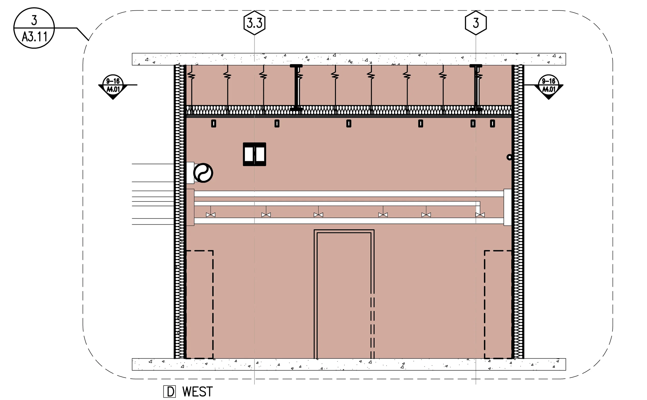
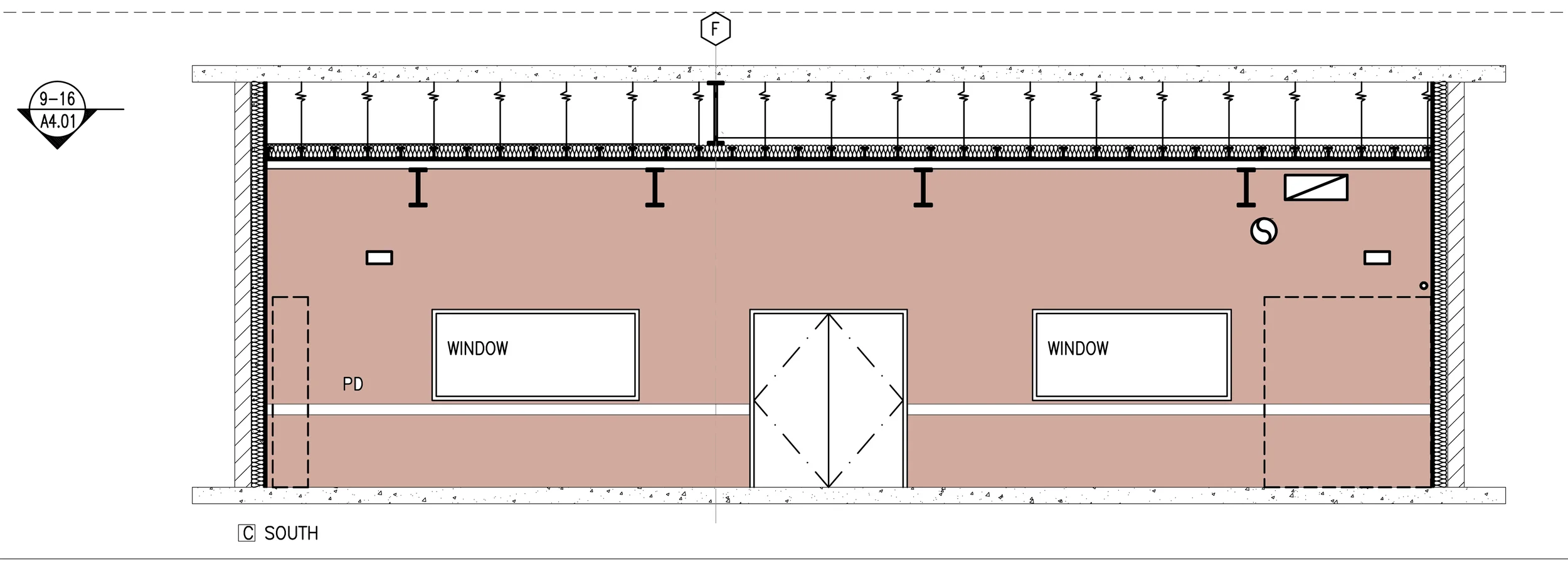
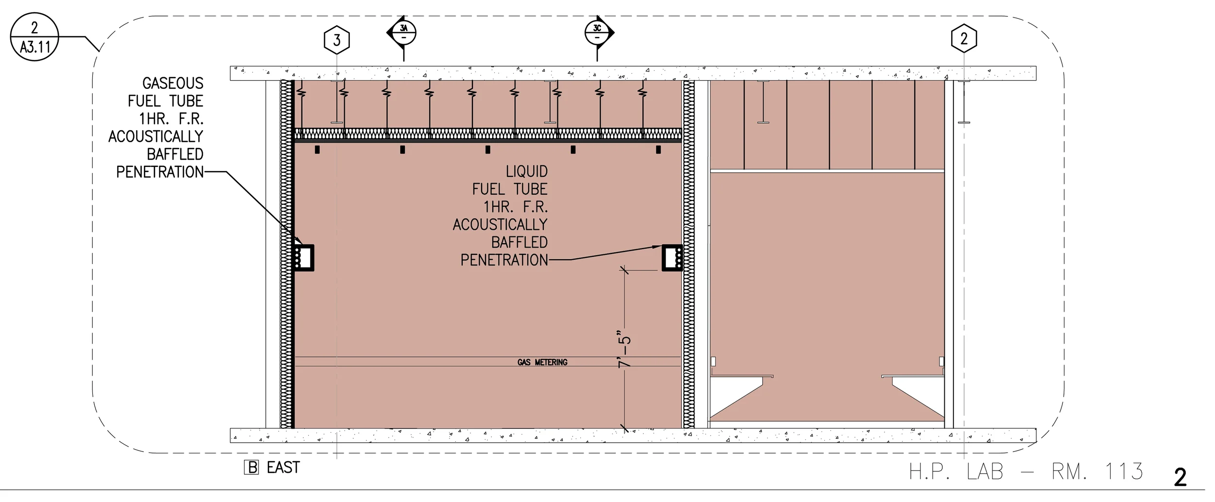


Stanford University Mechanical Engineering Building
Project Summary:
Architecture Firm: MBT Architecture, Seattle
Client: Stanford University, College of Mechanical Engineering
Date of Construction Completion: 2001
John Millard's Role: Project Architect for Combustion Science Laboratories (High Pressure Combuster Lab & Engine Laboratory)
Duration of Design Effort: Schematic Design- November 1999, Design Development- May 2000, Construction Documentation- October 2000

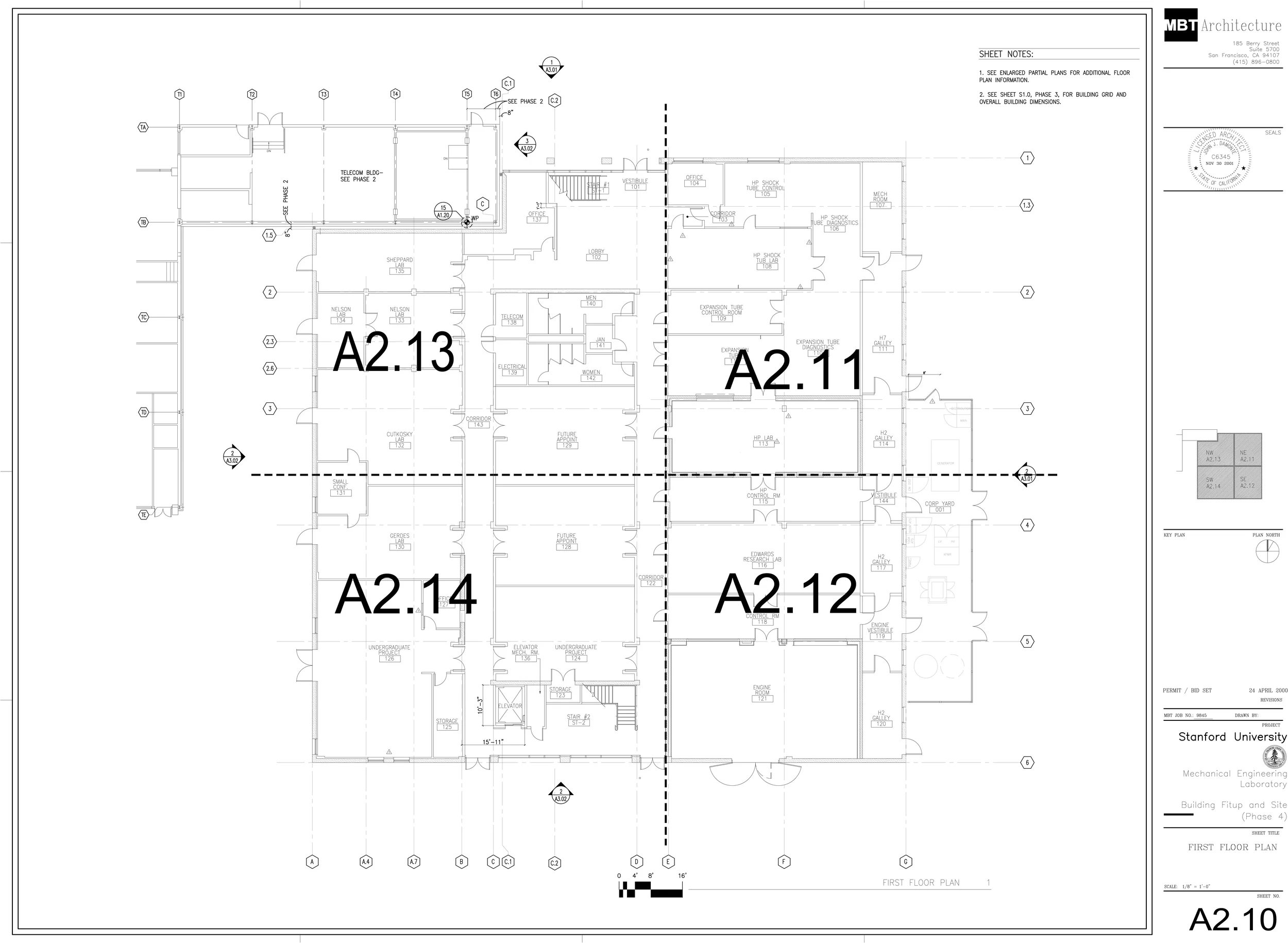






Multi-Custody, Large Corrections Center- Master Planned, Site Developed, Medical Center Designed
Project Summary:
Architecture Firm: NBBJ, Seattle
Date of Construction Completion: 1999
Architect Team Size: Concept Phase- 12 architects, Schematic Design- 15 architects, Design Development Phase- 18 architects, Construction Documentation Phase- 25 architects.
John Millard's Role: Concept Phase- JM authored the recommended Concept Design, Schematic Design Phase- JM role as "Site Architect" coordinated locations, functional adjacencies, topography, security and multi-disciplinary coordination of all 28 buildings with Civil, Mechanical, Electrical and Structural Engineers, Design Development Phase- JM was responsible for the design of the Medical Center, a multi custody facility with both in and out patient care for dental, trauma, psychological, and pharmaceutical services including a 12 bed infirmary with suicide watch and isolation units.
Duration of Design Effort:
Concept Design- August 1996
Schematic Design- January 1997
Design Development- May 1997
Construction Docs.- August 1997
BUILDING TOTAL AREA
200-acre site
COMPLETION DATE
Phase I—2000
TOTAL CONSTRUCTION COST
$160,000,000
OWNER
State Department of Corrections
JBM Role Synopsis:
This was my first full duration project at NBBJ where I was privileged to join the project team at inception of the design. The project was a 2000 bed, multi-custody corrections center for men (location not specified here for security purposes). Previous to this role, I assisted with various medical projects, later phase efforts in the Seattle Office of NBBJ. The Medical Center inside the fence at the Corrections Center would become my personal responsibility during schematic design/ design development & construction documents but first, the team needed a concept for a compact and coherent corrections campus that met with the approval of the Department of Corrections Consortium of Security, Administrative, Industrial, Wellness, Dental, Psychological, Trauma, InPatient, Pharmaceutical, Maintenance, Food Service, Laundry and Recreation Teams the sum of whom amounted to the opinions of nearly fifty people. The Concept Phase of the Project began with information gathering, diagramming, site modeling, site visits, correctional facility tours, committee formation, charettes, break-out groups, reporting requirements, chain of communications process, design methodology and group efforts that produce a great deal of information- but after several weeks of analysis of that information it was clear that producing a design by committee was running aground. Dozens of site plans were produced through a process of team effort across three teams of four architects each. These teams grew as the effort to produce a plan that the Corrections Team all agreed was suitable became stalemated and fruitless. The larger the teams of architects grew, the more opinions mixed into the deliverables which invariable were rejected as having fatal flaws or were considered inapplicable. There was one corrections expert on the NBBJ team who had several corrections facilities in his experience and he hovered above all the architects teams, assisting with security criticism and knowledge base. Perhaps it was the process of elimination of these several dozen schemes that was necessary to arrive at the recommended scheme, but in the end- it was the corrections expert and I, locked in a room with a roll of bum wad and a clutch of sharpies that brought the 100 person process to a close by authoring what is now known as "Scheme B4". Adoption of this scheme by the Corrections Team was similar to the moment when a bride tries on the winning dress, though not every bridesmaid was "on-board" with the solution. As with many large design teams, this corrections project team were surfacing with other "individually authored" proposals after weeks of team etiquette- architects pretending that design-by-committee works despite instinctive sense of awkward drawing after awkward drawing, the products of hybridized ideas harvested in a conversation of restraint and politeness (with a lot of passive aggression and frustrations). These other "individually authored" solutions were presented one after another to the client as each individual architect became more focused and in control over his or her own pen an paper, convinced that a solution was at the fingertips. Finally, the client was presented with three solutions, an official NBBJ statement from the design team read like this:
"Alternative Concept Evaluation During the planning and design process; three alternative concepts (C7, C8 and B4) emerged as candidates for further evaluation in order to proceed towards a recommended scheme. These were analyzed in a work session using a variety of criteria based on the Program Analysis and goals set collectively by DOC representatives and the Design Team. Pro's and Con's were documented and Concept B4 was selected and refined as the basis for development as the recommended option.
MASTER PLAN CONCEPT DESIGN PROCESS:
The following activities outline the process and work plan for the master plan concept development: 1. The Design Team and Department of Corrections visited the site to become familiar with site conditions. 2. A two-day kickoff charrette was held by the Design Team. Work plan tasks and approach to the development of a master plan concept were outlined: • Reviewed the work schedule. • Reviewed cost. • Deliverables were defined. • Established goals and quality expectations. • Defined consultant input and interaction. • Reviewed construction phasing. The DOC Planning Group attended the last half-day session. They reviewed the process and provided goals and objectives input. 3. The next effort was to research and setup for the concept development: • Preparation of and gathering of materials • Building a rough site model (scale coordinated with aerial photo) • Setting up a gaming approach and boards (grids applied to aerial and survey documents) • Reviewing and defining program components and relationship diagrams (Department of Corrections Policies) • Determining and setting appropriate program area building shape options • Defining infrastructure requirements, fixed conditions, code planning impacts and reading and understanding criteria (program, etc.) A work session was held with Department of Corrections to review and define program components and relationships. 4. A Design Team, multiple-option-study, kick-offmeeting was held to review research and setup material. 5. We then developed numerous multiple options. 6. DOC Executive Group met at NBBJ for an update on process and a review of work in progress. 7. After the options were completed a work session charrette was held with the Design Team and DOC, and three (3) options were selected for more detailed development. 8. The three (3) Options were developed. 9. An interim meeting with selected DOC security and operations people was held to review security and operational issues related to each scheme. 10. Another work session charrette was held with the DOC to select a recommended scheme. 11. The recommended option was adjusted and documented for Best Study. III.
SITE:
Description of Site- The Corrections Center will be located at the eastern edge of the Harbor. The site selected for the Corrections Center is atop a coastal ridgeline, and is surrounded along the western and southern edge by second growth forest and along the eastern edge by a ravine which contributes to the Existing creek drainage basin. Existing creek flows along the eastern toe of the property. The surrounding land uses include a landfill operation across the Existing creek valley, and an undeveloped ridgetop along the northern edge of the site, where the project access road will be located. The undeveloped ridgetop may be utilized for future industrial or residential development. The site is divided by a deep ravine and includes a tributary which is part of the Existing creekdrainage system. The ravine splits the ridgetop setting into two distinct buildable areas with a connecting plateau along the western side of the site. The Corrections Center location will include views across Grays Harbor and its surrounding landscape. The site has a high annual rainfall and the native vegetation is hemlock, cedar and Douglas fir forest. The northern portion of the buildable site is vegetated with a seven to eight year old growth of juvenile forest. The southern half of the site has recently been logged and only shrub cover remains. The deep ravine in the center of the site contains a series of lush native wetlands and a dense grove of large, mature alders. The ravine is of high habitat value for wildlife and provides visual interest against the dark evergreen forest.
RECOMMENDED CONCEPT:
Description The concept plan for the proposed facility is based on the Correctional Center Program Analysis Update, June 28, 1996. The following excerpts from this analysis are included in Section V (Functional Area Diagrams) of this report for reference. 1. Space Summary: Correction Center 1 vs. Correction Center 2 which lists the space needs. 2. Correction Center 2 List of Building/Functional Groups corresponding to the Space Summary. The Concept Site Plan drawing that follows this narrative description illustrates the recommended concept plan. The proposed facility is located on the southern plateau of the site with its main pedestrian entrance near the northwest comer of the plateau. The main secure component of the institution is enclosed by an electronically monitored double-security fence with a patrol road around it. The overall configuration of the secure perimeter has its longer side in the east/ west direction. It accommodates all the "inside" program components within it following the adjacency/relationship diagrams developed during the planning process. The location and configuration of the Concept Plan has also been developed with the following in mind: • Conform with the required setbacks, easements and clearances. • Avoid or reduce negative impacts on the slopes and wetlands on and around the site. • Reduce extensive earthwork fills. The main approach road from the north as it enters the site will be monitored by intercom. After this check there are two clearly defined choices for access routes towards: • The main pedestrian entry and parking on the north boundary of the secure perimeter. • The "outside" service facilities on the northwest of the perimeter and the vehicular sally port on the west.
Pedestrian Entry: The main pedestrian entry is located on the north of the secure perimeter towards the west comer. All staff and visitors must enter through this entry. Entry is authorized after verification of ID and security screening as needed.
Administration: "Outside" Administration is located west of the Pedestrian Entry building to allow free access into the office areas after initial screening. The main access into the secure part of the facility is through the pedestrian sally port, which will be controlled by the Major Control room located south of this area with direct sight line observation. "Inside" Administration is on the east and south of the sally port providing direct access to the rest of the facility.
The Armory/Staff Services Training: This building is located on the west side of the "Outside" Administration building with easy access for staff.
Visiting: The General visiting area is located on the west side of the pedestrian sally port. Once visitors clear ID check and screening, they are allowed into the visiting area by major control. Inmates enter through a separate entry on the south end. ID check and screening occurs immediately after admittance before entering the visiting area. After visiting, inmates return to this area where they are checked, screened and searched to eliminate contraband before they return to housing. Attorney visiting and group meeting rooms will be located in this building with adequate separation from general visiting. Non-contact visiting booths will also be located in this area adjacent to the entry check. Inmates using these booths will be separated from the visitor area.
Vehicular Entry: Vehicles entering the facility branch to the west from the access road check point and then tum south and proceed towards the vehicular sally port, which is located on the west side of the perimeter.
The General and Industries Warehouses, Vehicle Maintenance and Central Plant buildings are located along this route on the northwest of the facility. The vehicular sally port gates are controlled by the Guard Tower with CCTV monitoring. A guard station located in the sally port screens all vehicles in and out of the facility.
Layout Inside the Perimeter: The overall organization and layout of the facility inside the perimeter is made up of several zones to facilitate clear definition of functions, flow and separation and containment of inmate groups.
General Housing: The MI-3 housing units, along with the Medium housing unit, are approximately located in the middle of the facility in a row.
The Inmate programs and services zone is located on the southwest side, and the Outdoor fitness yards are located on the northeast side in rows paralleling this housing. These yards are collectively enclosed inside a secondary fence. The housing units are paired with adequate separation (40 feet) between units. The gaps between the units also provide multiple accesses to the yards.
Inmate Services and Programs: The Inmate Programs and Services building is subdivided into zones for Education, Health Care, Intake, Food Service and Indoor Wellness Fitness areas. The Education and Health Care components will have some functions on the second floor to facilitate adequate daylight into rooms. The Indoor Wellness Fitness Program areas are located towards the southeast end of the building with a direct path to the yards. A walkway along the length of the building provides a well-defined circulation area with clearly identifiable entry points. The loading/service yard is located on the south side of this composite building with direct access to the Kitchen, Intake and Ambulance access to Health Care. View of this area is concealed from inmate areas. Industries, Vocational Education and Plant Services: The Industries, Vocational Education and Plant Services are located along the south side of the perimeter. The building will be planned as modular bays to allow multiple industries to operate independently. The Vocational education spaces will be located along the north wall of this building. Future expansion of this building will be to the west. The loading/service area for this building stretches along the south face of the building to serve multiple industries independently. This also provides a clear separation of the industries and facility-related service areas. The Plant Services component is located adjacent to the Industries building on the east end. A single point inmate entry is provided from the north side of the building to facilitate screening and flow of inmates.
Minimum Security Housing: The Minimum Security housing unit is located on the western portion of the facility in close proximity to the vehicular sally port to facilitate convenient movement of these inmates to work detail outside the perimeter. The Mud room for check, search and clothing change is located outside the perimeter close to the vehicular sally port. The Minimum housing area can be separated from the rest of the facility with a secondary fence. Inmates from this zone will mix with the general population and go to the services and program spaces on a prescribed schedule.
Higher Security Housing: The Youthful Offender housing and the Maximum/Segregation housing are located in the northwest comer of the facility in a separate zone. The Max/Seg units are located on the northwest comer of this zone with cells facing away from the rest of the facility. The location is close to the visiting area building with a secure connection to facilitate controlled visitor access to the Max/Seg unit. The Youthful Offender housing is located south of the Max/Seg housing building in close proximity to the Intake area in the Inmate Services building.
Other "Outside" Buildings: Buildings other than the Pedestrian Entry and "Outside" Administration that are located outside the perimeter fence include Industries and General Warehouses, Central Plant, Vehicle Maintenance buildings and the Water reservoirs which are located in a row parallel to the west edge of the upper plateau of the site. The north/south run of the vehicular access road runs along this row of buildings to provide easy access to the vehicular sally port, which is to the south or towards the approach road of the highway (north). Areas are also earmarked for miscellaneous buildings such as Recycling (north of this area) and a Firing Range on the east side of the north plateau. Guard Tower: This facility is based on the concept of a single guard tower. The prescribed highest priority for the location of the guard tower is to be able to visually supervise the fitness yards, the family visiting area and the sweat lodge. The secondary priority is to be able to supervise the vehicular sally port and the service yards. Additionally, the tower should be able to observe incoming traffic from the approach road onto the site. With these criteria in mind, the guard tower has been located on the north side of the perimeter fence west of the Main Public entry.
Site Work and Utilities: Summary descriptions on Site Development, Civil, Structural, Mechanical and Electrical are included here along with Conceptual diagrams of the Utilities.
SITE DEVELOPMENT:
The concept locates the primary facilities within the southern half of the site. This location will minimize the visual impact of the facility from off-site vantage points. The proposed layout will minimize the amount of cut and fill necessary within the ravine. The diagonal site layout will provide the opportunity for landscape terracing within the facility. This will minimize earthwork and create distinct use areas within the Corrections Center. Scheme can incorporate storm water detention facilities within the eastern end of the southern plateau, and a separate detention pond for the parking area within the northern plateau. The microclimate created within the layout will provide southwestern exposure to the central walkways, which will maximize sun exposure and drying of walkway areas. The layout will also orient the entrances to the living units in the direction of the prevailing winter winds and create a windy, rain-driven entrance. The design of buildings will need to consider this factor. The plan provides a good solar orientation for the recreation fields. The location of the facility within the southern plateau takes advantage of the recent forest clearing within this area. The majority of the juvenile forest along the northern plateau will be preserved under this development plan. This will retain both additional wildlife habitat and vegetative buffer for the sensitive ravine environments. Vehicular access to the site will be functional and the division of traffic between the parking area and the service entrance will take advantage of topographic site opportunities. Pedestrian circulation within the site will be channeled along a central corridor and travel distances will be minimized between living units and service areas. The location of the facility along the southern plateau will minimize the impact of security lighting on the surrounding vicinity; however, glare from the lights will be visible from the surrounding ridgelines. The Scheme will have an excellent visual sense of entry to the Corrections Center. The location of the entrance road in relationship to the administration building, combined with accent landscaping, will create the opportunity for developing a positive institutional image. The location of the outside industries and warehouses along the western edge will create a buffer between any future land use of the adjoining western parcel and the Corrections Center.
WATER UTILITY:
The water supply will be furnished by the City of Aberdeen. Water will be supplied to 2 - 150 foot tall standpipes located on high ground on the west side of the north plateau. One standpipe will be for domestic supply, the other for fire protection. Domestic demand on the peak day is estimated at 1100 g.p.m. Fire demand is 3250 g.p.m. for 4 hours or 800,000 gallons, with a minimum 20 psi residual pressure. All buildings will be sprinklered and exterior hydrant spacing will be on the order of 300 feet. Distribution piping will be mostly 12 inch diameter ductile iron pipe. Water demand for irrigation is included in the above figures.
SANITARY SEWAGE UTILITY
Sewage waste will be delivered to a City of Aberdeen facility adjacent to SR1 05 and then pumped back to Aberdeen for treatment. The on-site collection system consists of 8 to 12 inch gravity sewers. Schemes, which occupy the south plateau, require a pump station and force main to lift waste to the north plateau. Collected waste on the north plateau will flow by gravity to a second lift station near the top end of the new access road. It is then discharged to the Aberdeen facility at SR1 05. STORM DRAINAGE UTILITY Storm runoff in the area is extensive, averaging 86 inches of rainfall per year and 4 to 5 inches in 24 hours. On-site storm collection will be carried in closed pipe ranging in size from 12 to 24 inch diameter. Storm water will be diverted to detention ponds and possibly bio-filtration swales prior to discharge into existing creek and its unnamed tributaries. Pre-treatment of runoff from parking lots and vehicle wash facilities may be required.
EARTHWORK On-site soils are not good with regard to use as a base for structures. The soil has a high fines content and is not capable of the required compaction for use under structures because of the high moisture content. Soil classified as cut will be classified as unsuitable. This includes the top 12 to 18 inches, which is high in organic material. The requirement for imported fill material will be high, driven primarily by the need to level the site for security reasons. The footprint of some schemes intrudes on the ravine that divides the overall site into two plateaus. The ravine is a designated wetland and the filling of it and other wetlands require a permit from the Corps of Engineers. The primary intent of the final grading plan for the selected site will be to reduce the amount of imported fill to the minimum possible.
Foundations • It is anticipated that all of the buildings will be located on structural fill as determined by the geotechnical engineer. • Some initial settlement could occur and will have to be considered in the structural design. • Some heavily-loaded or settlement-sensitive structures may have to be supported on high capacity foundations such as auger cast piles. These may include water and fuel storage tanks, lighting towers, and the guard tower. • It is recommended that additional geotechnical information be obtained when the final site layout has been selected. This information should include the soil bearing capacity, lateral soil pressures, and soil friction factors. Borings up to 30 to 40 feet deep, and one boring up to 60 to 70 feet deep may be required. Buildin~s Possible types of construction that are to be considered include: • Tilt-up concrete. • Pre-cast concrete. • Cast-in-place concrete. • CMU with special reinforcement and grout-filled cells. • Structural steel. • Possibility of wood construction for buildings where security is, not a strong consideration. Other considerations relating to the design of the buildings include: • Establishment of efficient modules that will allow duplication within the various structures. • Special security requirements for exterior and interior walls may control the design. • Special consideration must be taken for crack control due to settlement of foundations. • Other special requirements that may effect the design. May include hoists, cranes, or other heavy equipment, or long-span requirements.
Site / Utilities • Water or fuel storage tanks could be cast-in-place concrete, pre-cast concrete, or steel construction. • Utilidors could be cast-in-place or pre-cast concrete construction. Water protection will be required. • Oil/water separators could be obtained and installed as complete units, or they could be designed to be built on site. Other site / utility structures to be considered include: • Pump stations. • Site lighting towers. • Guard tower. • Retaining walls. • Emergency generators' installations. • Stack at power plant.
Mechanical System: The main utilities serving the Site have a direct path to the Power Plant and do not impact the construction of Buildings within the Security Fence. Adequate access is provided for vehicles to service the mechanical equipment located within the Power Plant. The site plan allows for a direct path for the installation of utilidor containing heating piping, domestic cold water piping and electrical conduit. The Power Plant is located to provide future expansion to the North Plateau.
Electrical Power and Communications Service: Electrical and communications services will be coming to the site along the entry road, which enters the plateau at the northwest corner. It is therefore advantageous from an electrical service standpoint to locate the power plant and associated electrical service nearer to the northwest corner. Site Distribution: The compactness of the site should result in minimized cost for power and communications distribution. The power and communications distribution may be located in the utilidor or run separately in ducts and manholes. An analysis of these two options should be performed at the Schematic Design Phase.
Power Distribution System: The power will be distributed throughout the site at 12.47 or 13.8 kV and stepped down to 277/480 or 208/120 volts via pad-mounted transformers. The system will be designed to maximize flexibility and reliability. Due to the compactness of the site, locating pad mounted transformers will require careful consideration. Emergency Power: Central emergency power will be provided to maintain the facility in operation during an extended power outage. It is assumed that the generators will be located in or near the power plant. The generators will be diesel powered, designed to start automatically upon loss of utility power. It is anticipated that three generators will be provided, sized to allow one generator to be de-activated at any time for maintenance or repairs. Site Lighting: Lighting poles will be situated throughout the facility to provide the desired level of general illumination for security and scheduled activities during darkness. Light fixtures will be cutoff type to minimize "light pollution" to surrounding areas. Perimeter fence lighting will be provided for security.
BUILDING SYSTEMS ASSUMPTIONS
FOUNDATIONS:
STANDARD SPREAD FOOTINGS
ASSUMES GOOD BEARING SOILS - NO DRILLED PIERS
SUBSTRUCTURE:
SLAB ON GRADE - ASSUMES NO BASEMENT
SUPERSTRUCTURE:
CONCRETE DECK UPPER FLOORS ON CMU & CONCRETE BEARING WALLS
CONCRETE DECK ROOF ON STEEL FRAME STRUCTURE
EXTERIOR CLOSURE:
CMU BEARING WALLS WITH INSULATION AND CMU VENEER FACE BLOCK
POLYCARBONATE GLAZING AT SECURE AREA WINDOWS
ROOFING:
BUILT-UP ROOFING AT LOW-SLOPE ROOFS
STANDING SEAM METAL ROOFING AT GABLED ROOFS
INTERIOR CONSTRUCTION:
PAINTED EXPOSED CONCRETE AND CMU WALLS
PAINTED GYPSUM WALLBOARD AT SELECTED DRYWALL CONSTRUCTION
EXPOSED CONCRETE FLOORS WITH RESILIENT FLOORING IN SELECTED AREAS
EXPOSED CONCRETE CEILINGS WITH ACOUSTIC TILE IN SELECTED AREAS
CONVEYING SYSTEMS:
MINIMUM REQUIREMENT HYDRAULIC ELEVATOR ACCESS IN MULTI-STORY INFIRMARY
MECHANICAL:
HEATING AND COOLING FROM ROOFTOP UNITS
FIRE PROTECTION SPRINKLER SYSTEMS THROUGHOUT
ELECTRICAL:
ALL LIGHTING AND POWER ON EMERGENCY POWER
TAMPERPROOF FLUORESCENT LIGHTING"





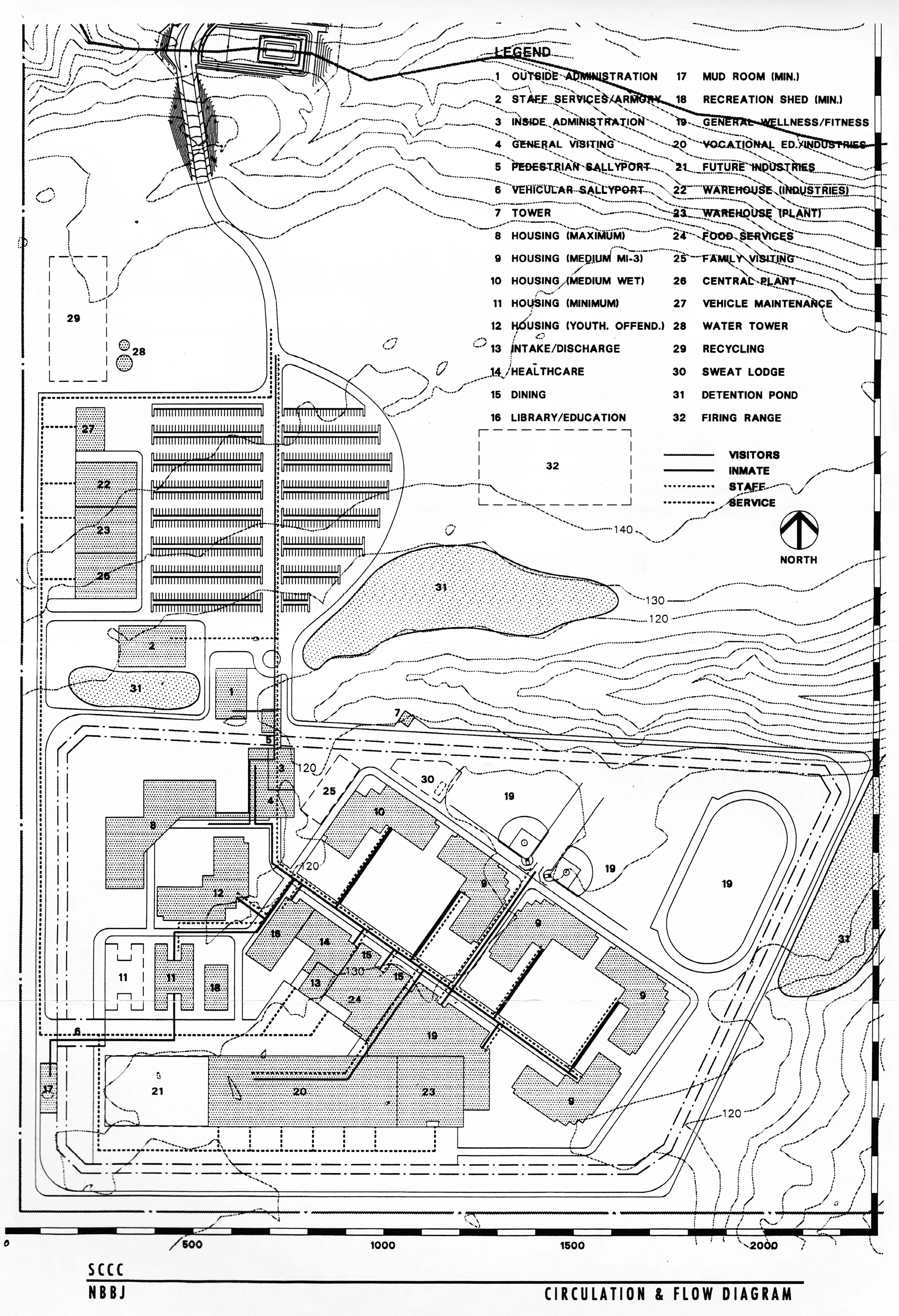
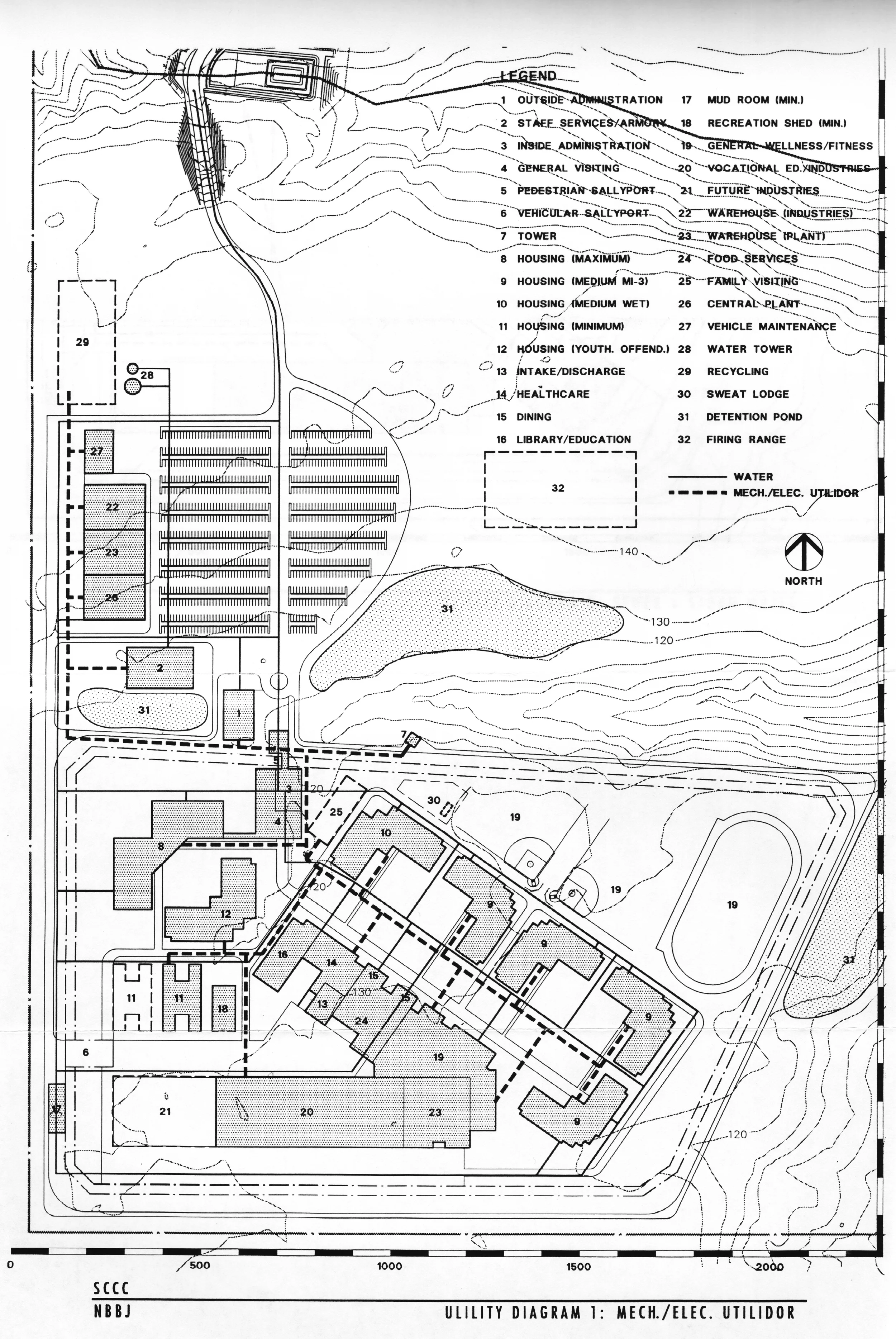

The "mouth" of this series of interconnected inmate program buildings is the "feature" of Scheme B4 that solved so many design problems that irked rectilinear schemes that were characteristic of earlier concepts rejected by the Department of Corrections Team. The benefits of this simple device to self segregating the "deliveries" to the facility from the "internal circulation" of the inmate population were a breakthrough of the concept which retained this quality right through to construction.
Over the eighteen months of design and documentation, the feedback from the department of corrections further enhanced the "mouth" of the facility where the intake of new inmates, industries materials, ambulance, and food are all protected from visual or physical access by inmate traffic. This aspect of the inmate programs buildings configuration survived and evolved over many many months of schematic and design development phases of the project.

From CNN: The organic vegetables travel a short distance from the well-tended garden to the table where they are eaten. Waste is carefully picked through and recycled, saving thousands of dollars. The close-cropped lawns are maintained by push mowers to cut down on carbon emissions and gas expenses. This is not some new designer eco-hotel where the rich and environmentally conscious can be pampered free of guilt. It's a prison. At the The Corrections Center, a few yards from the garden where strawberries and cucumbers grow looms a tower where guards watch inmates, high-powered rifles at the ready. A jungle of razor wire surrounds the facility.

When ecologist and professor Nalini Nadkarni first pitched the idea of prisons going green she didn't know how her proposed partners -- convicted criminals -- would respond. "Would they be full of tattoos with shaved heads? How would I connect with them?" Nadkarni recalled thinking, "They turned out to be the easiest audience to connect with. They have been so open so wanting to learn, so desirous to connect with the environment." With the programs that Nadkarni and other instructors from the Evergreen State College helped devise, hundreds of inmates not only have a positive impact on their prison environment but on the world beyond the walls confining them.


Inmates are restoring local protected but disappearing grasslands by hand planting thousands of seedlings in a prison greenhouse. This has helped me get my head back on and stay out of trouble. --inmate Tyson Prater Inmates at another state prison raise an endangered species of frog. The inmates work for less than a dollar an hour and as a result of their incarceration are able to take on time consuming and labor intensive projects. But the inmates are not just doing grunt work.


"They are observing, taking notes, what they are doing is science," she said. Both ecologists and prison officials have been surprised by the passion and seriousness of the prisoners involved with the project, Nadkarni said. The inmates raising the frogs had better results than a group of scientists conducting a similar project in a lab. Nadkarni coauthored a scientific paper with one inmate. Another surprise has been the savings involved in the project.
"In the beginning a lot of the motivation is just around the money," said state deputy director Dan Pacholke, who green-lit Washington's first environmental programs behind bars seven years ago. Just at Stafford, officials saw savings of close to $200,000 a year just byrecycling trash instead of paying to have it hauled to a landfill. The benefits have gone far beyond fiscal savings, Pacholke said. "When you get into it you find there's a lot you can do to get inmates involved in other programs whether it be gardening or recycling. Over time you are trying to connect offenders with something that is meaningful or with purpose that they feel is valuable and give them activities that offset the costs of prisons themselves." Pacholke said officials have seen a drop in violence among prisoners participating in the program and the state plans to expand the program from four prisons to all 13 institutions. Inmates volunteer for the program and can't have any infractions or they get kicked out. Inmate Toby Erhart, halfway through an 18-year sentence for rape and incest, said his work in a prison garden allows him to contribute something to society. "Just because I am incarcerated it doesn't have to be a negative thing," Erhart said. "I see a lot of people being affected negatively and it doesn't have to be like that. I look forward to coming to work ever day. How many people can say that on either side of the fence?" As he added scraps of food from the prison mess hall to a compost heap, inmate Tyson Prater said he too feels fortunate. "This has helped me get my head back on and stay out of trouble," he said. Prater said he is hoping to pick up the skills that would allow him to work for the U.S. Forestry Service when he is released from prison in three years. Prison officials say that the program prepares inmates to work in certain sectors of the growing green jobs field. It also makes them environmentally conscious citizens who know about recycling, sustainable farming and conservation when they are released, they said. Pacholke said the greatest dividends the program may provide may actually take place outside of prison. "[About] 97 percent of the people in here are getting out some day and are going to ride next to you or I on inter city transit," he said "So what's the experience you want them to have when they come back out to the communities?"

Pharma Research Lab Flexibility


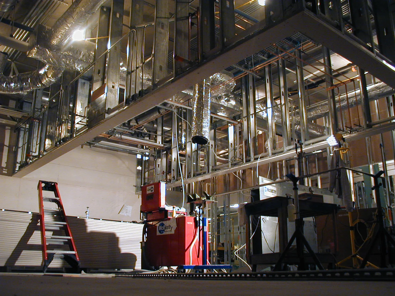
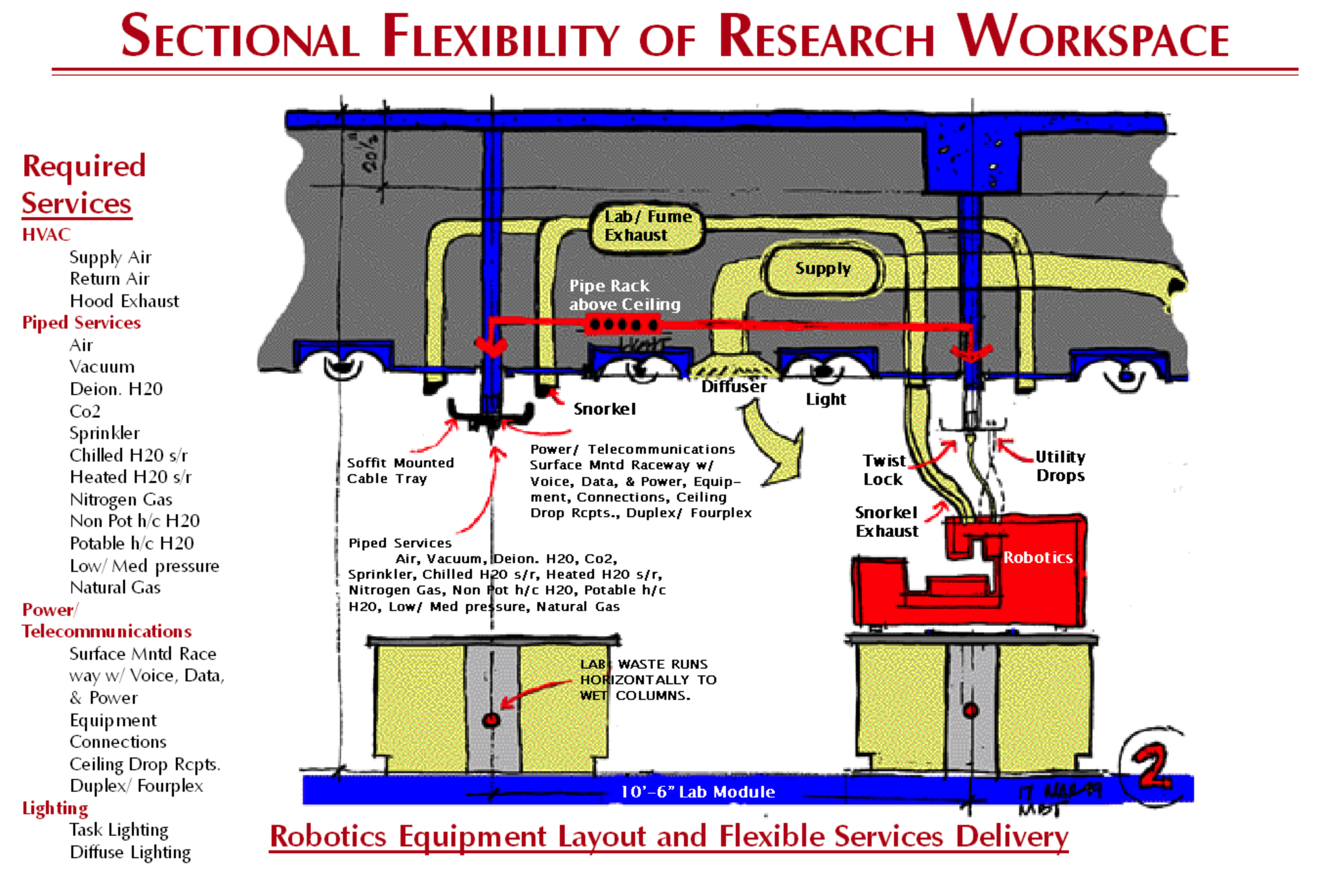
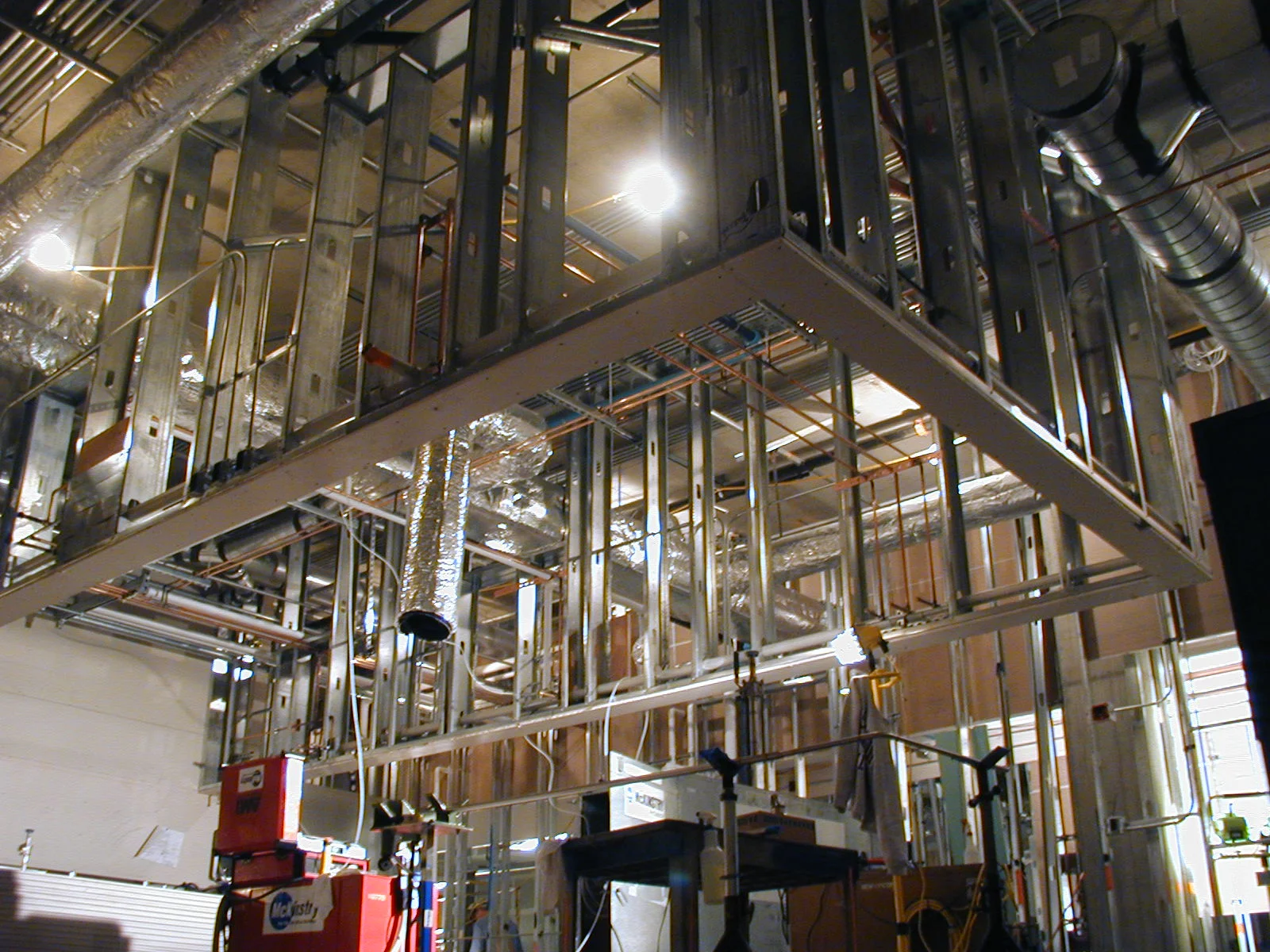
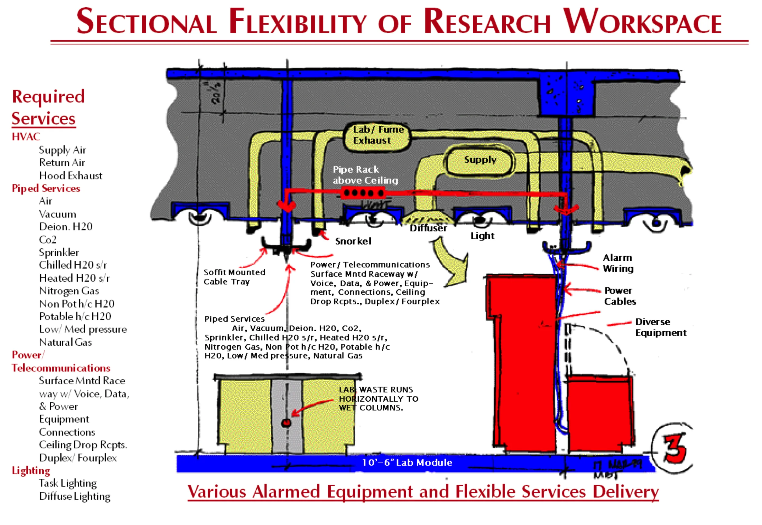
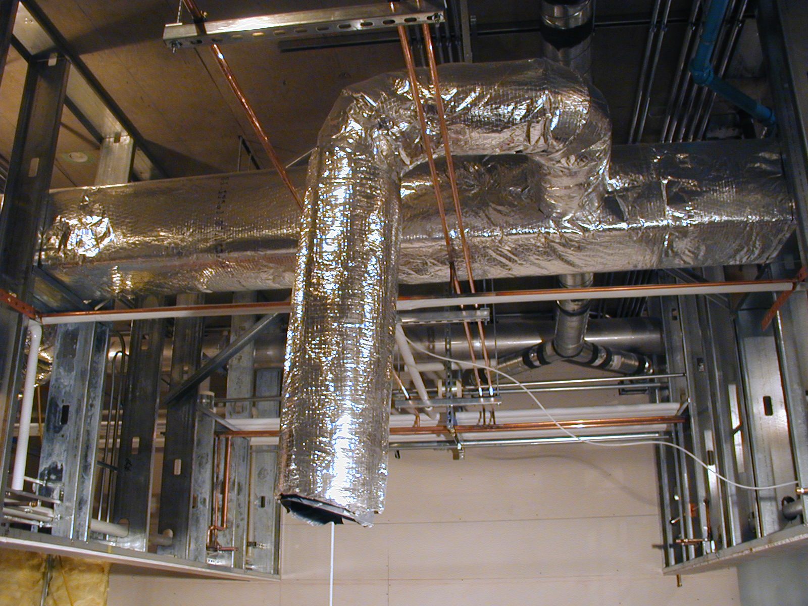


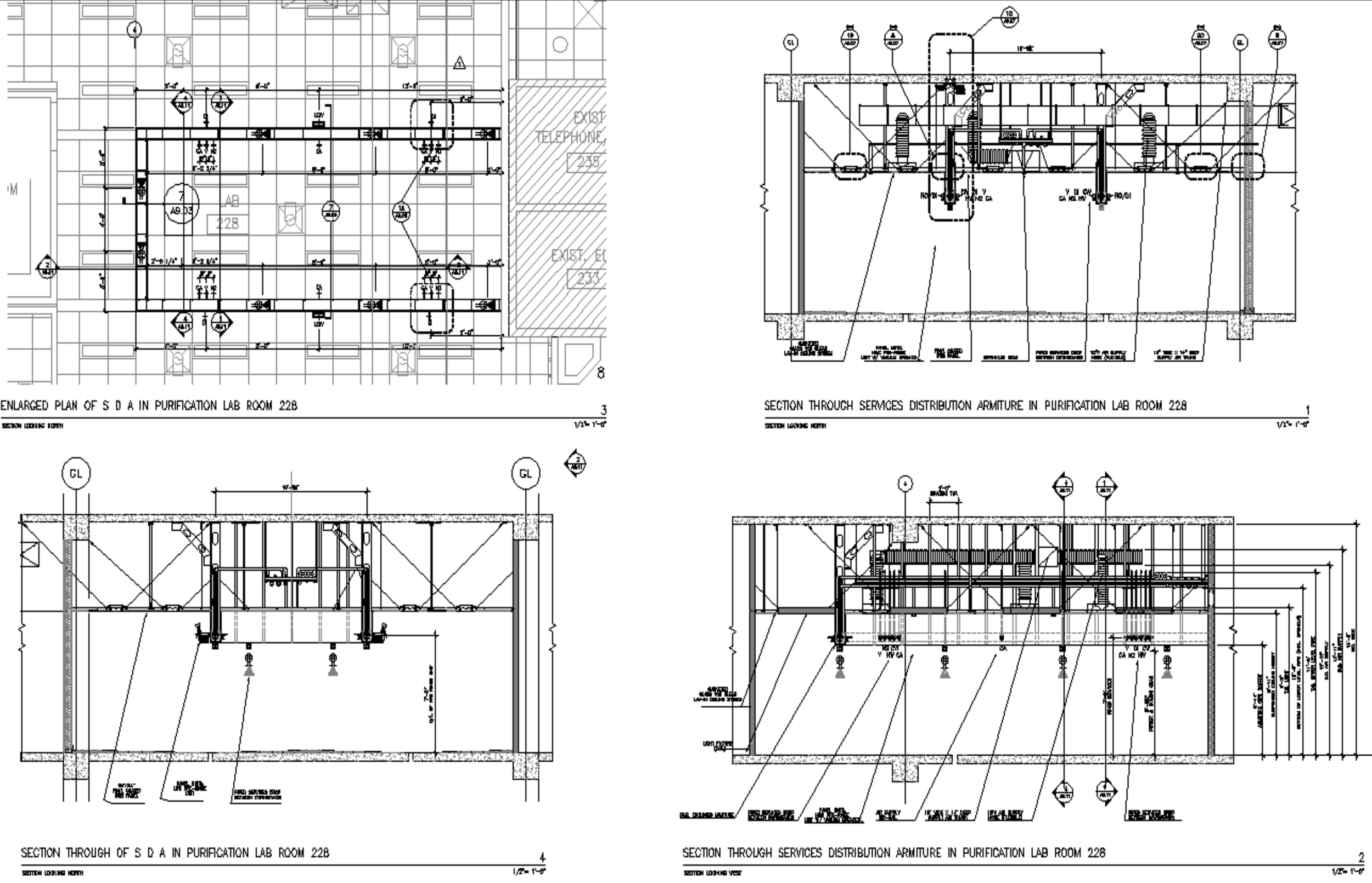

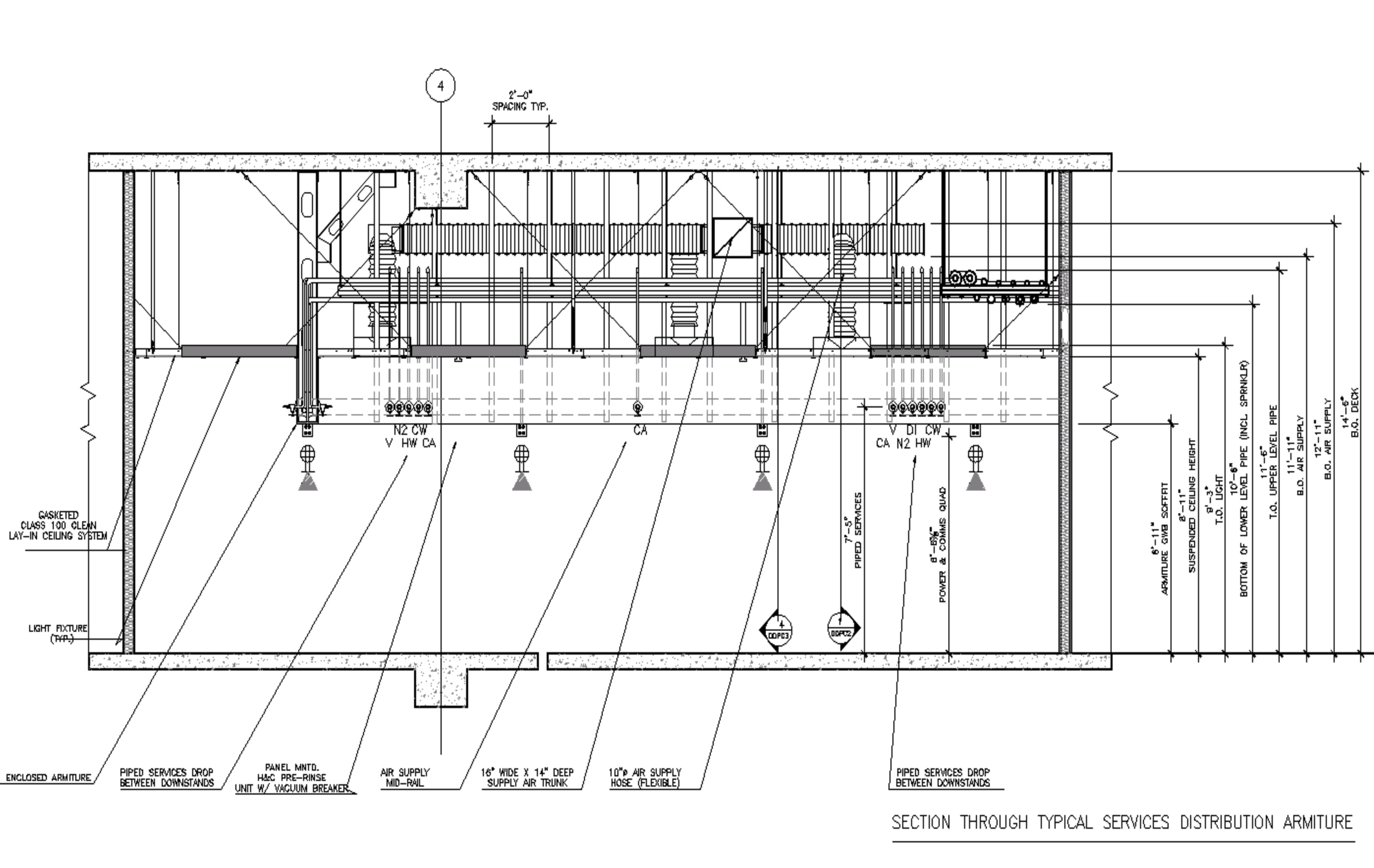

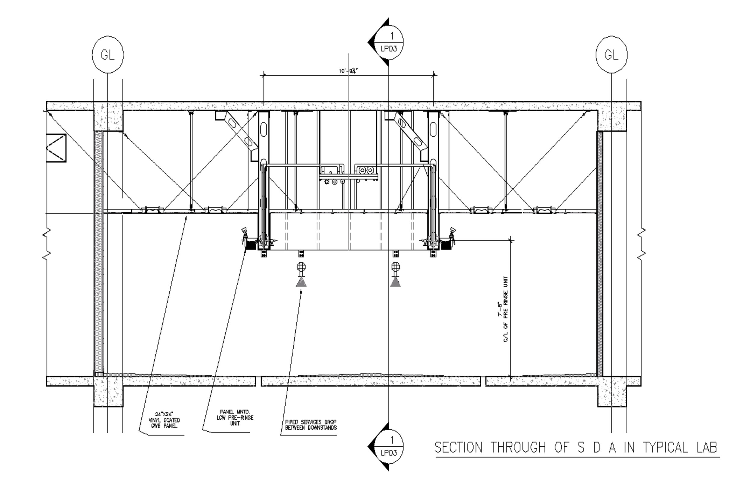
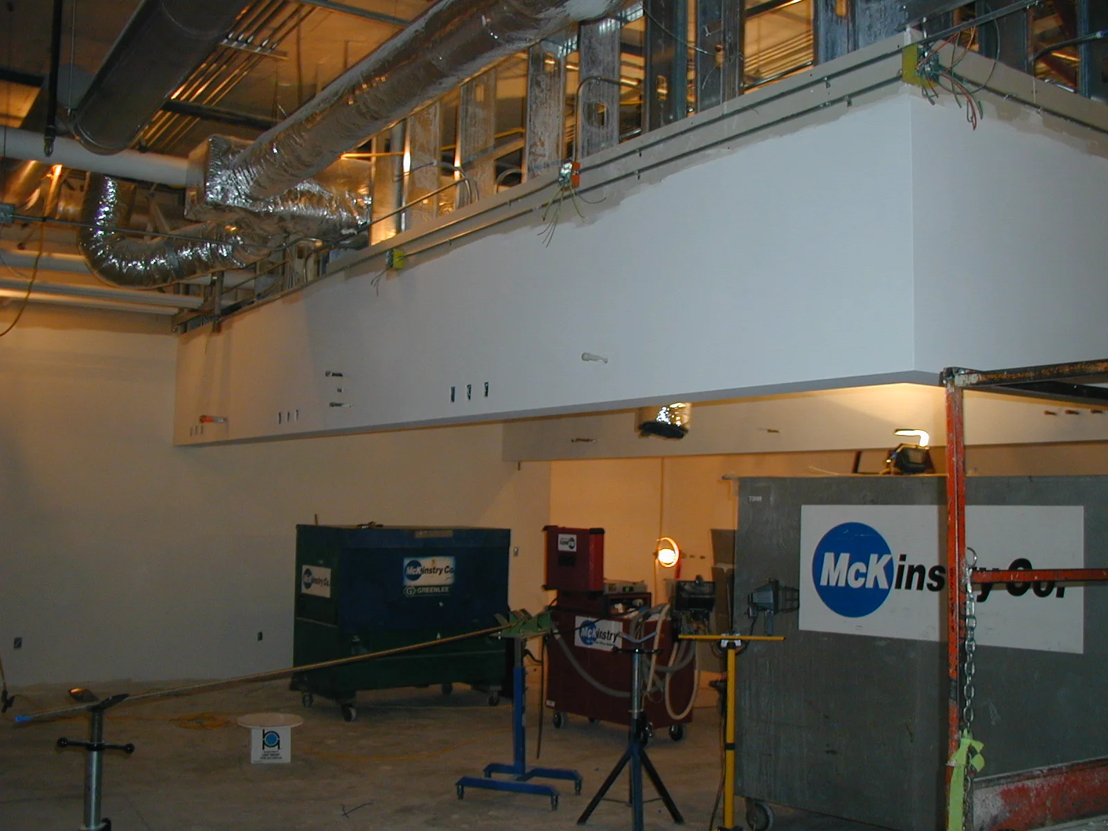
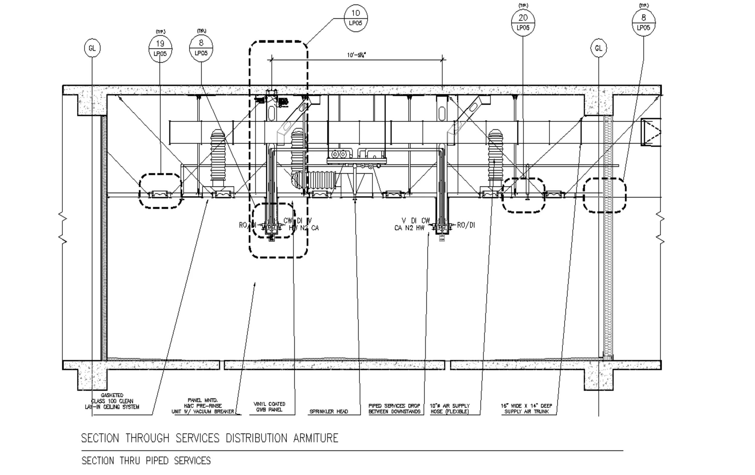
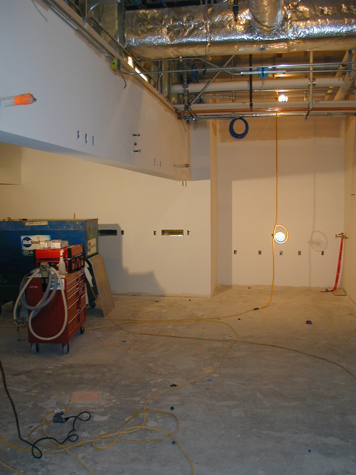
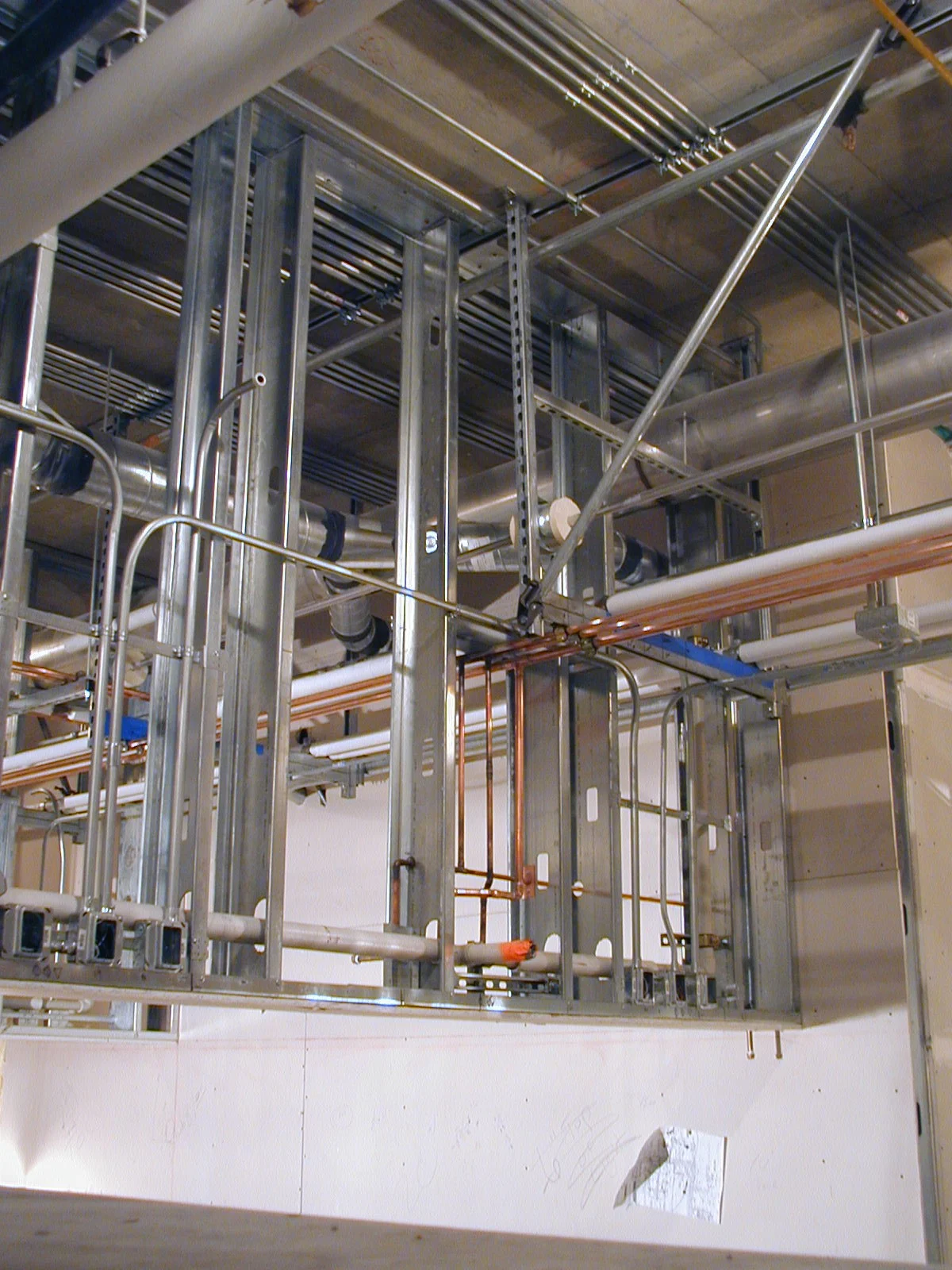

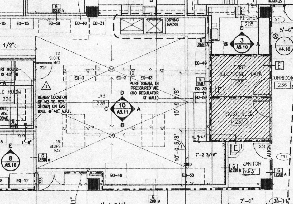

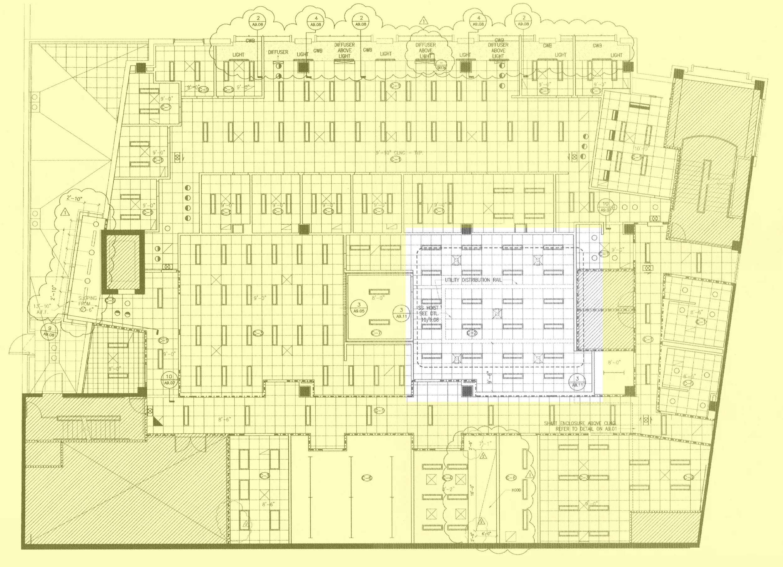

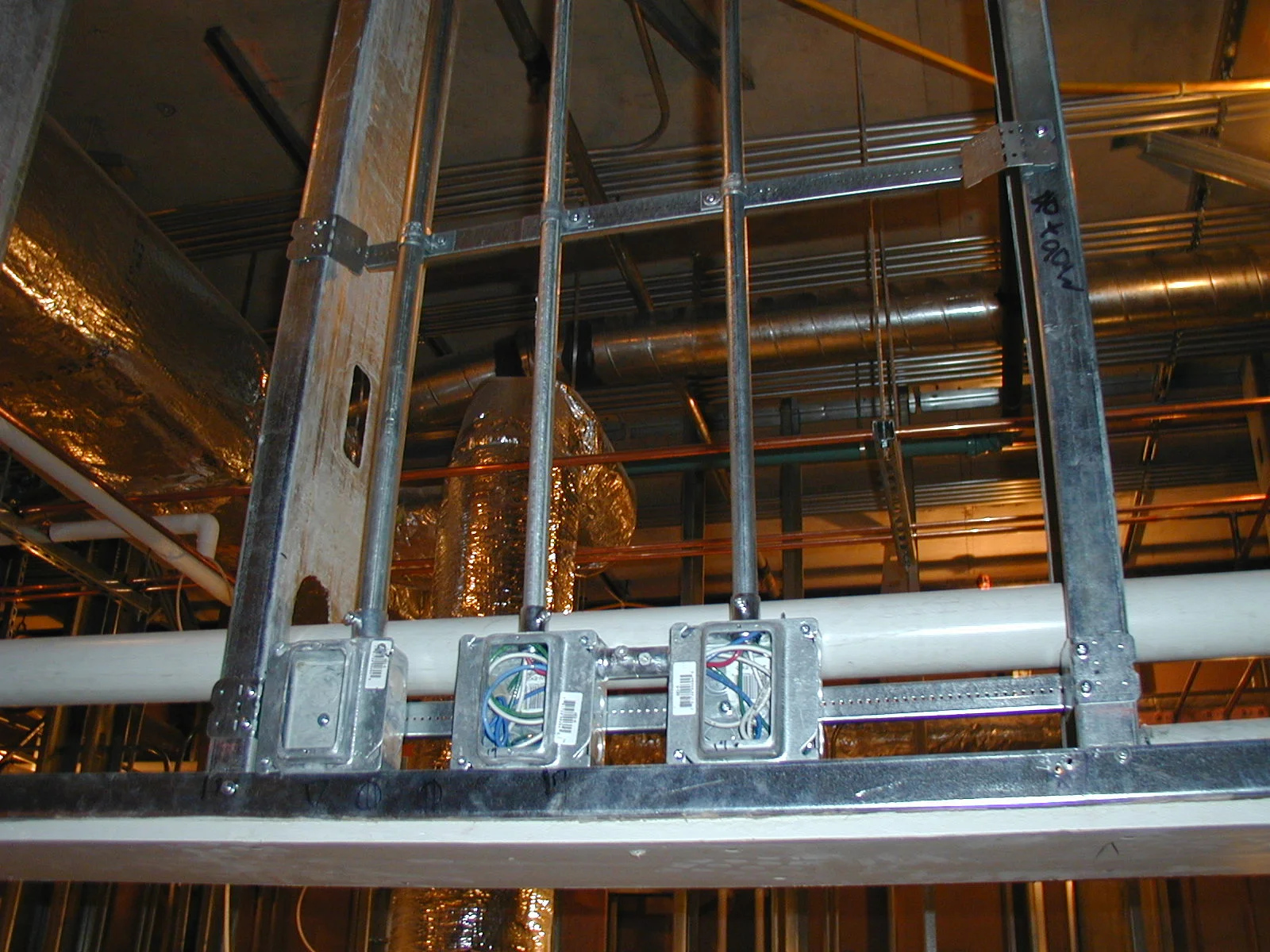
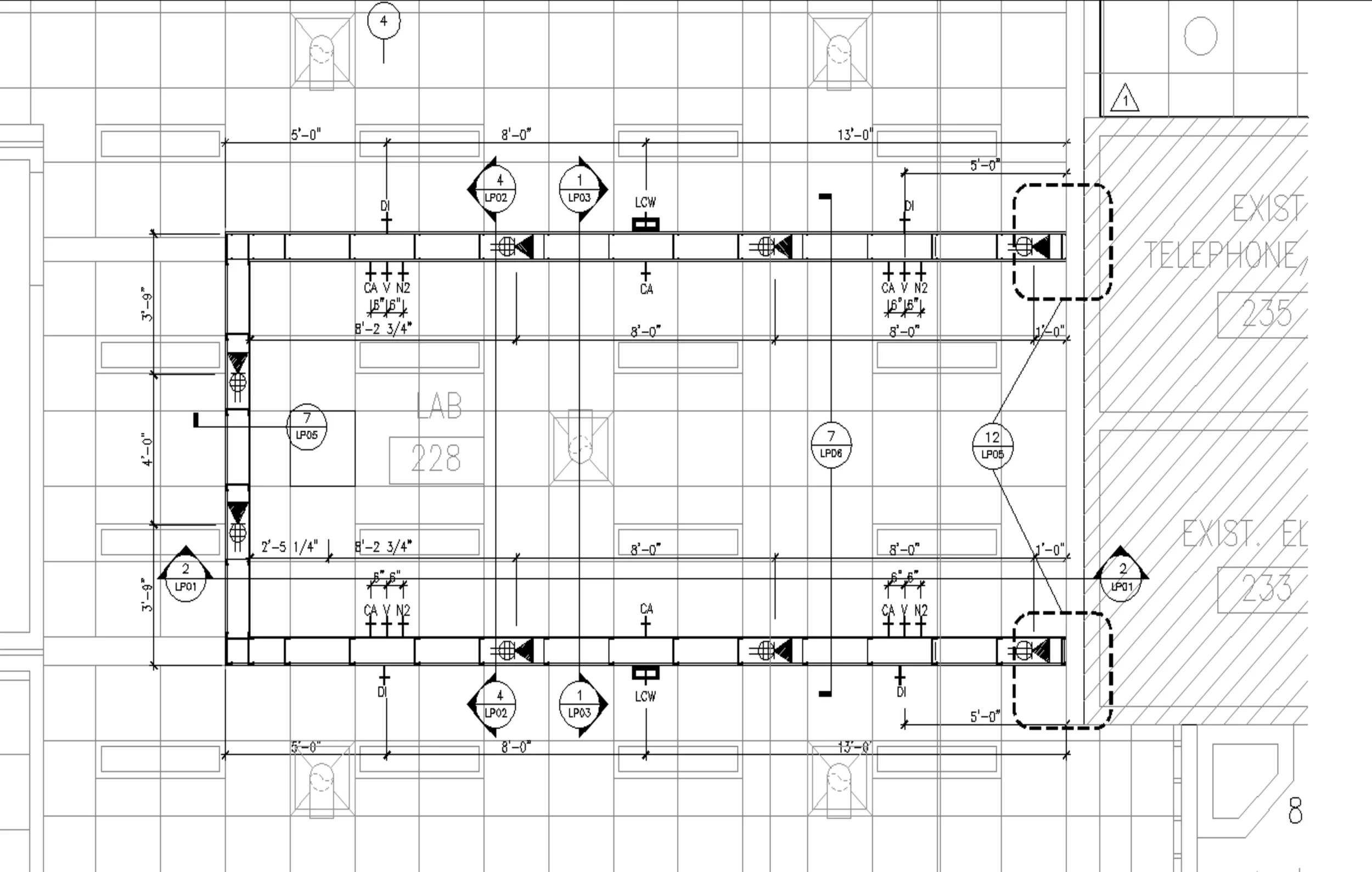
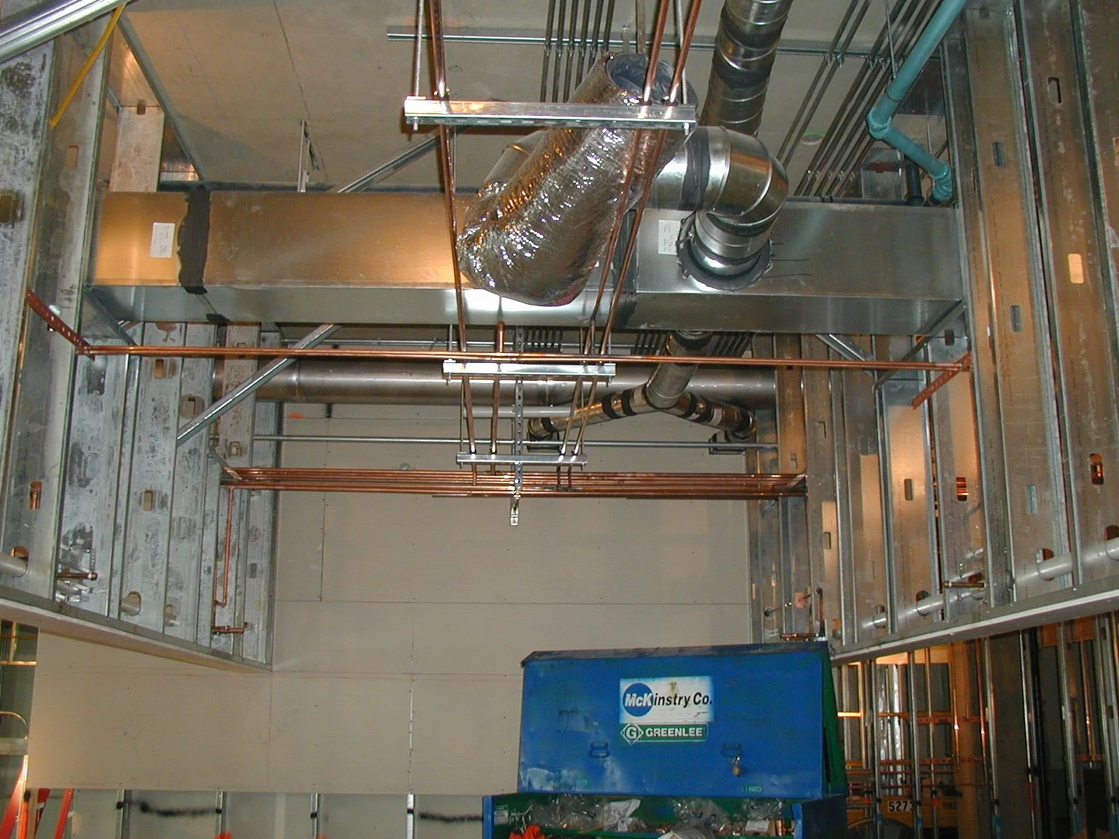



High Rise Laboratory for University of Washington/ Seattle Children's Hospital
Architecture Firm: MBT Architecture
Client: Cornerstone Properties
Site: 9th Avenue & Stewart, Seattle
Date of Project: 2001 (Schematic Design)
Project Description: The Development is six floors of lab and office space over a base containing Entry, Retail, ·and Building Services. Below grade will be one level for special vibration-sensitive equipment. Access to parking for 200 cars above grade and truck docks will be off the alley. With a projected building occupant load of 1 person per 400 GSF it is anticipated that 2 truck docks will adequately handle the delivery and haul-offneeds of the facility. The entry level of 27,028 square feet will include 4000 + Square feet of retail space with the balance going to Lobby and Building Services. Two and a halflevels of parking and six levels of lab and office above the ground floor will rise to 136' - 0". Taking the full floor plate to this height is a departure from the setback at 125' above the street. Each will be 27,960 S.F. with 14'-0" clear below structure. The 9800 SF penthouse will house elevator equipment, chillers, building exhaust, specialty exhaust systems and stairs. This size is a departure from the 25% limit on penthouse area relative to floor plate. The architectural structure will enclose mechanical equipment.
Role by John Millard: This project was my last role prior to leaving MBT and going to work for Laboratory Planners McClellan Copenhagen. MBT's client, The Touchstone Corporation, engaged MBT to prepare a program, concept and schematic design package of drawings that would lead to a design review by city planners in Seattle's planning and zoning process. I was one of two architects working on this project together with the Principal Architect on the project to produce the early design guidance for one of the first speculative laboratory high-rise projects in the city.


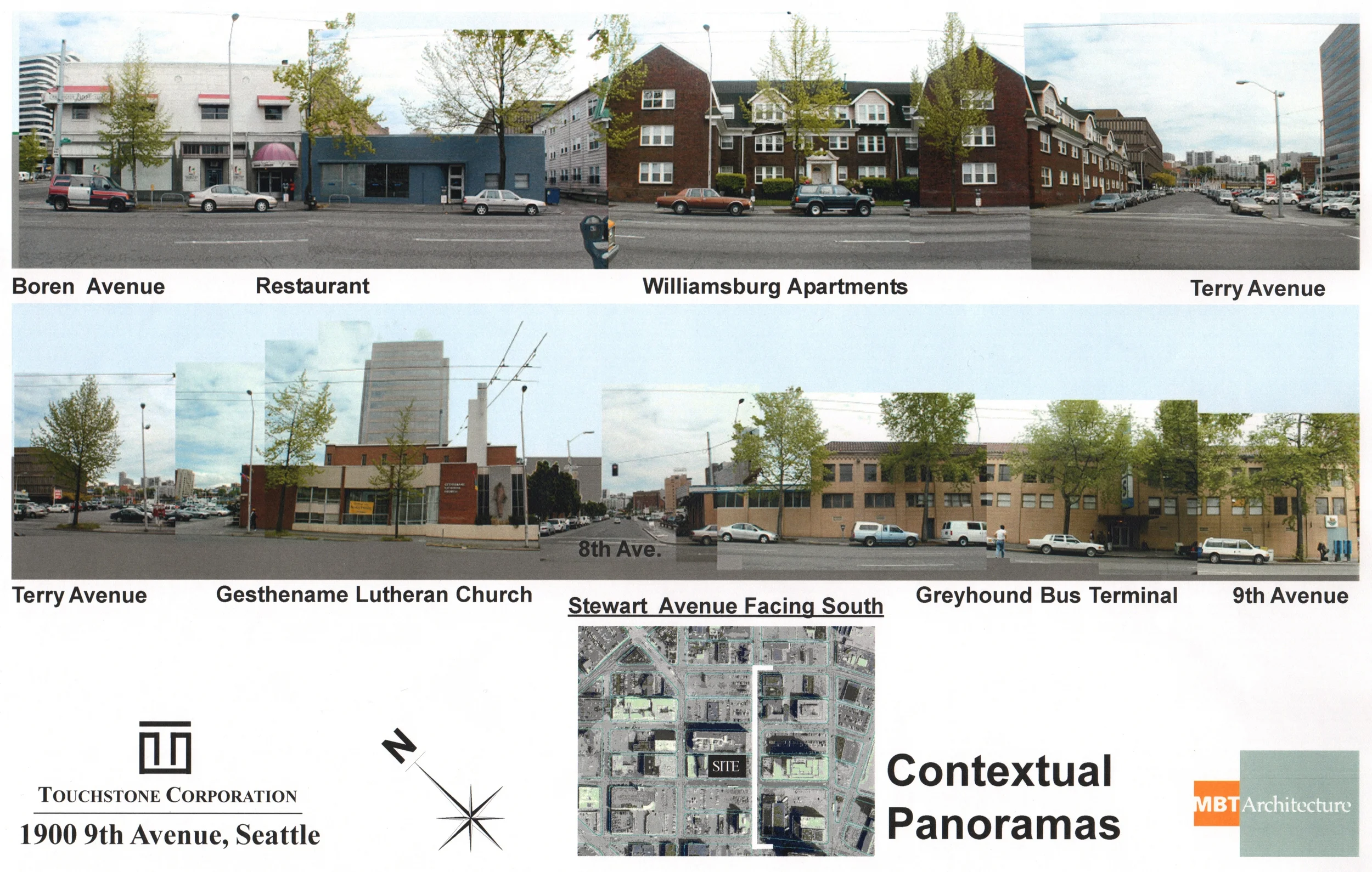
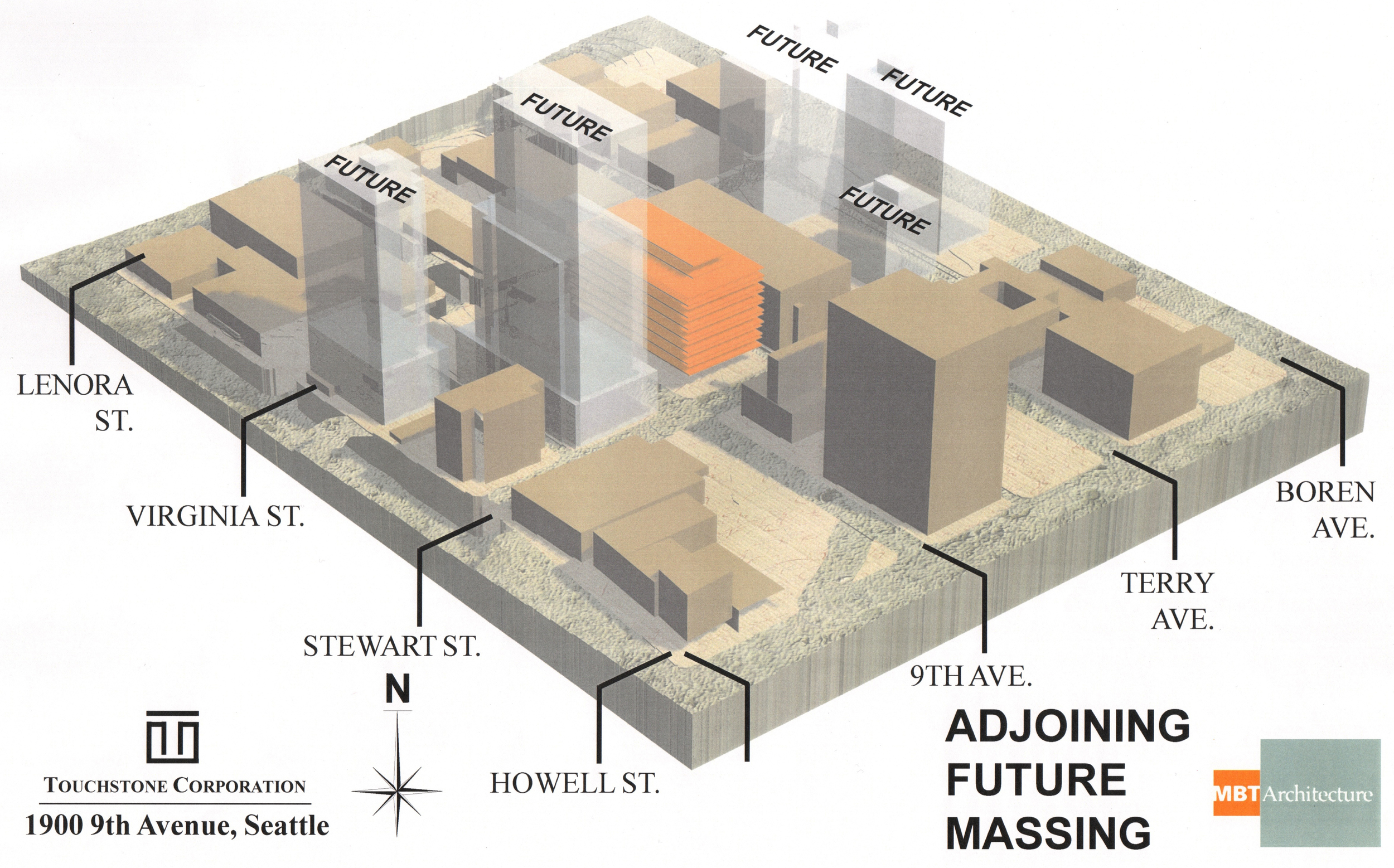

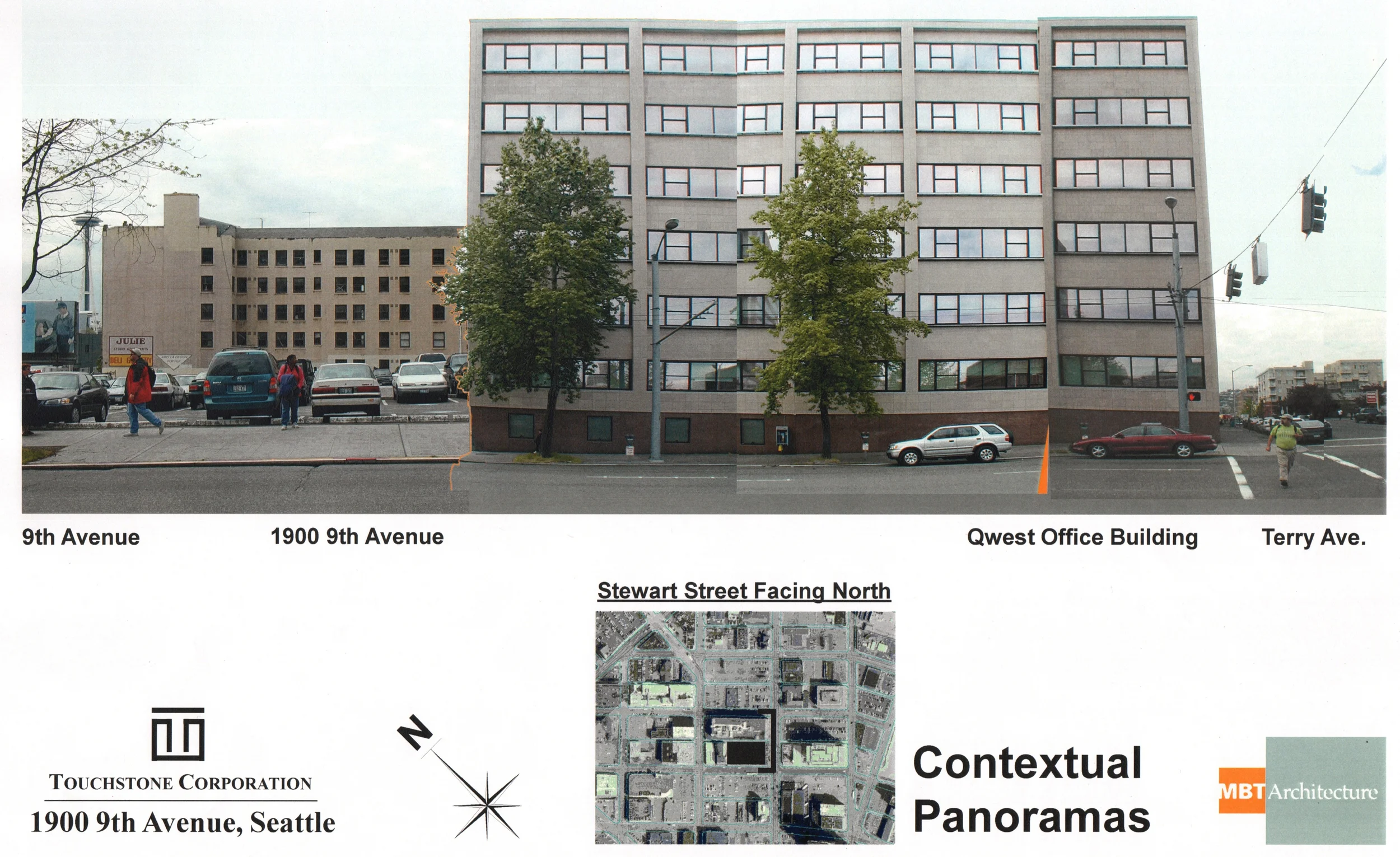
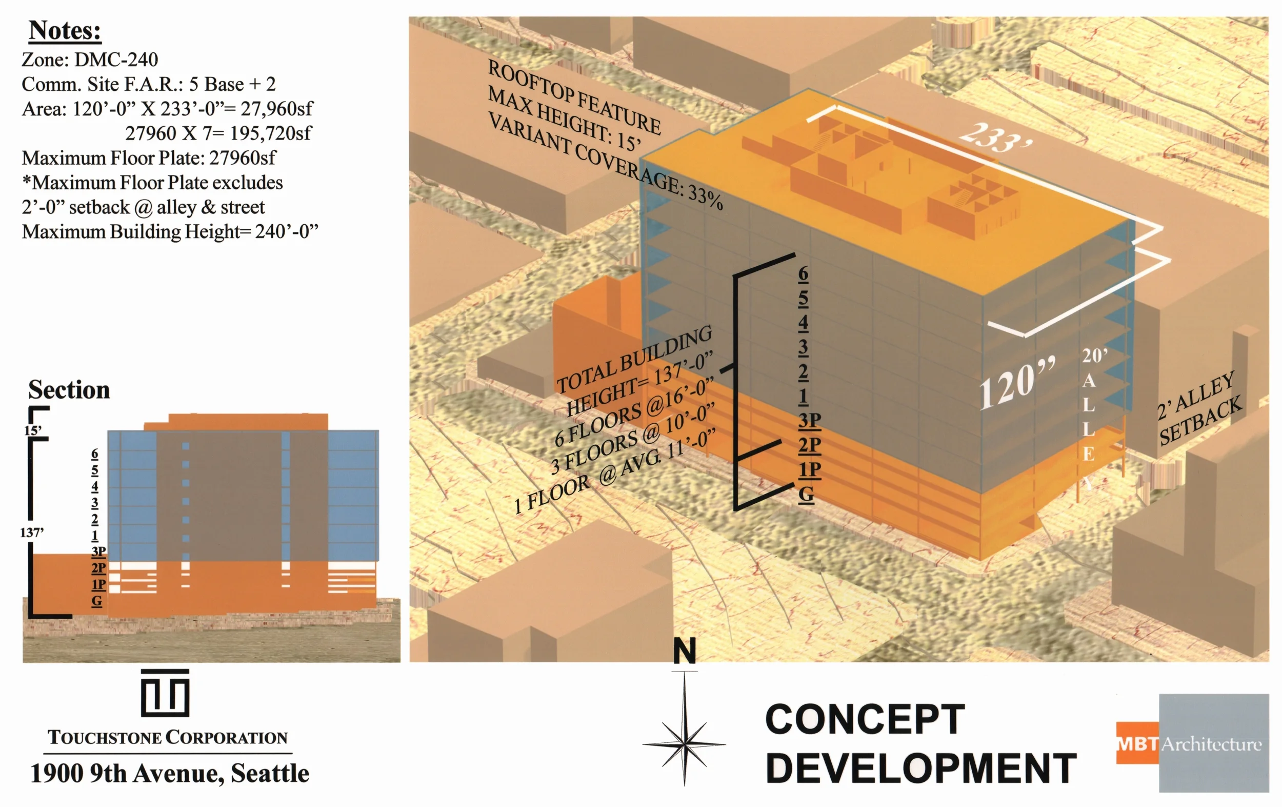


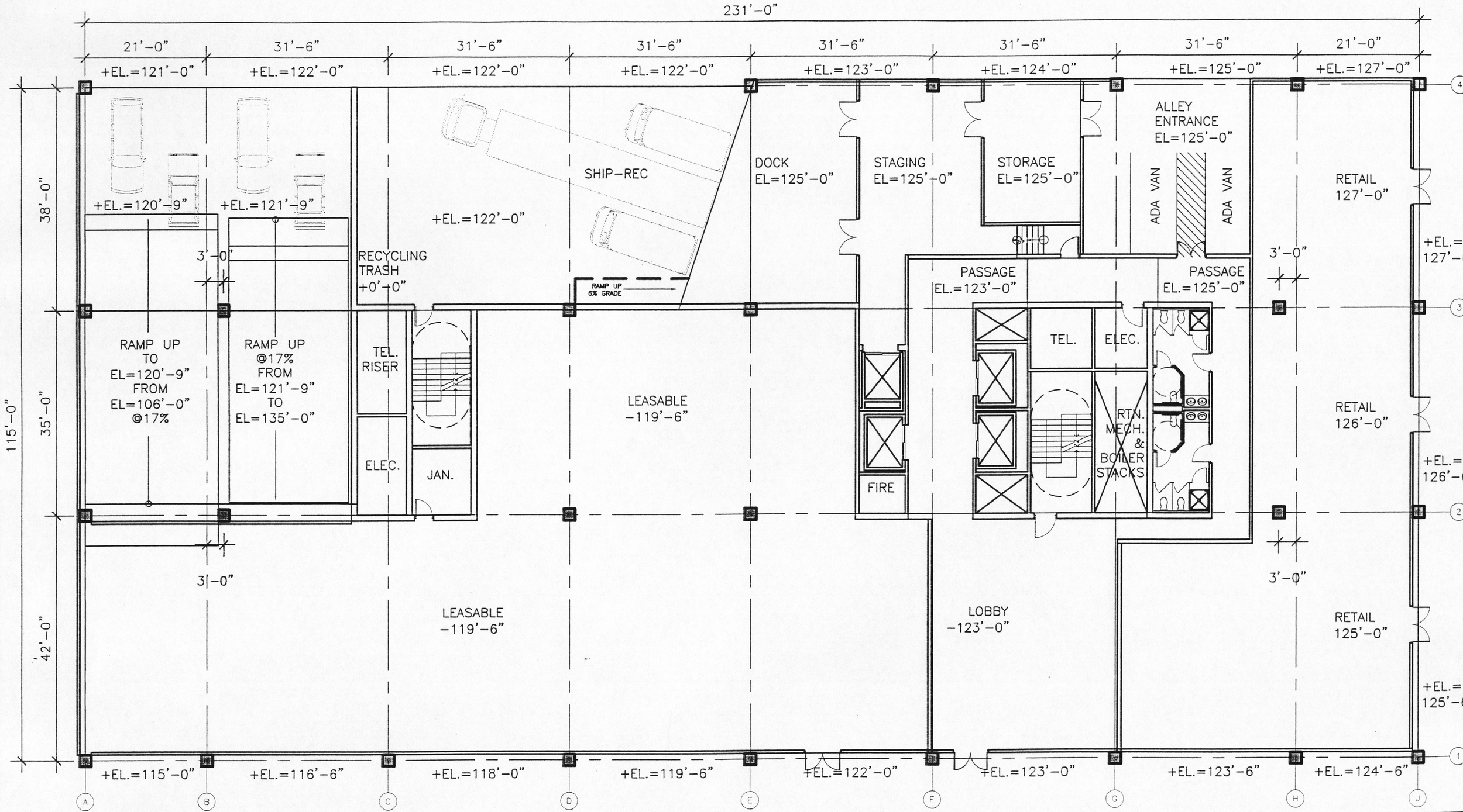

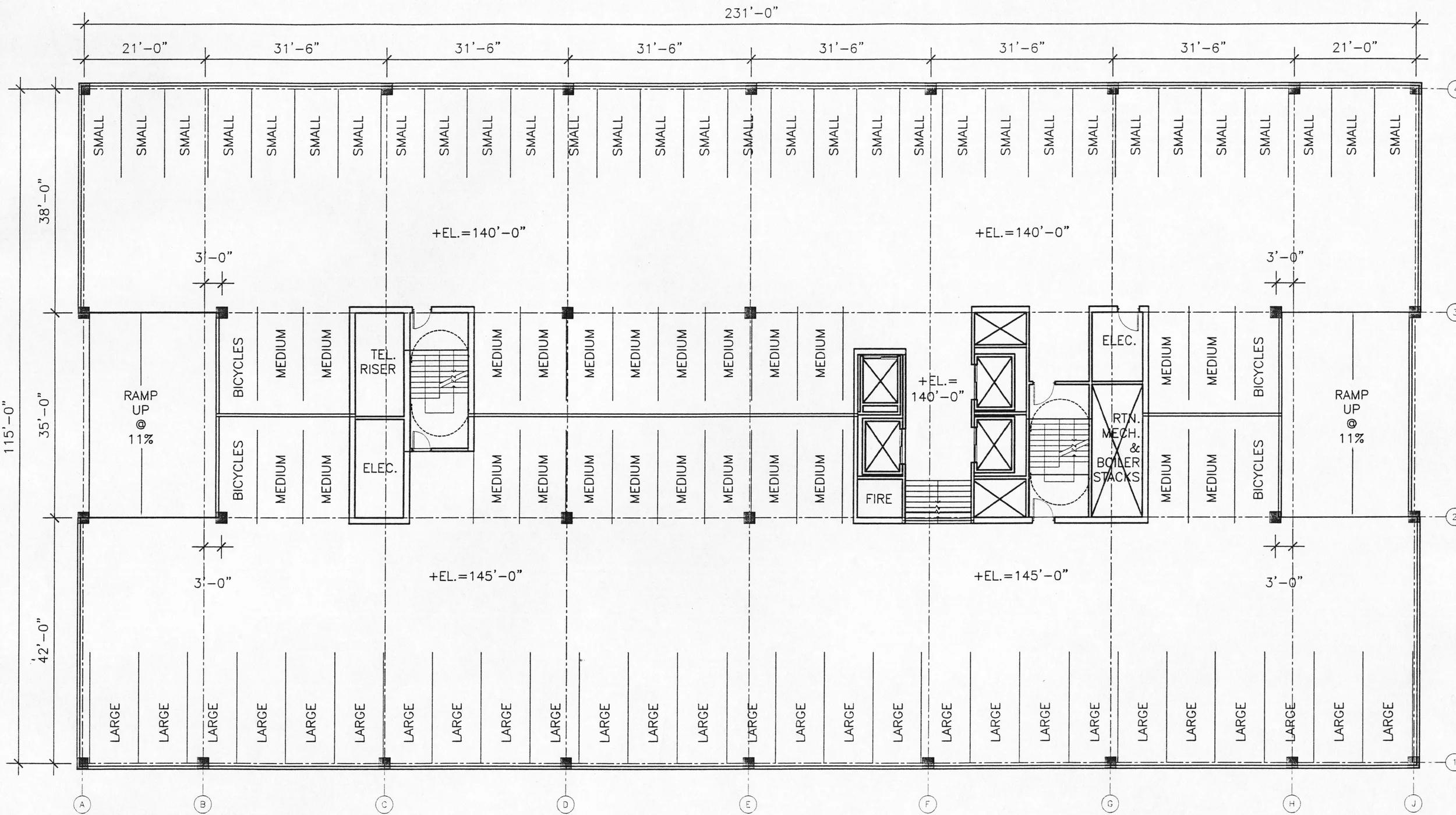
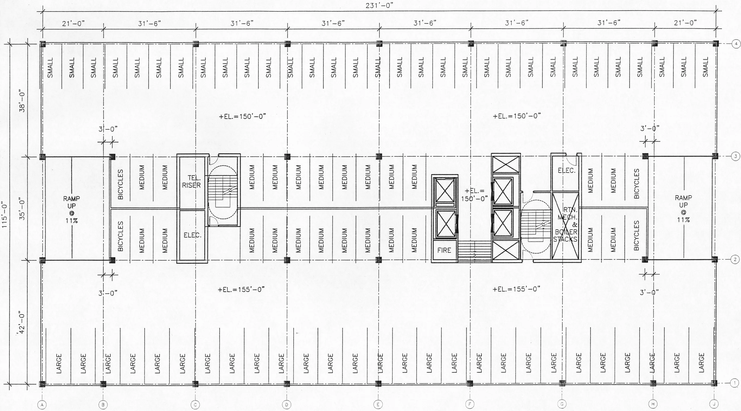

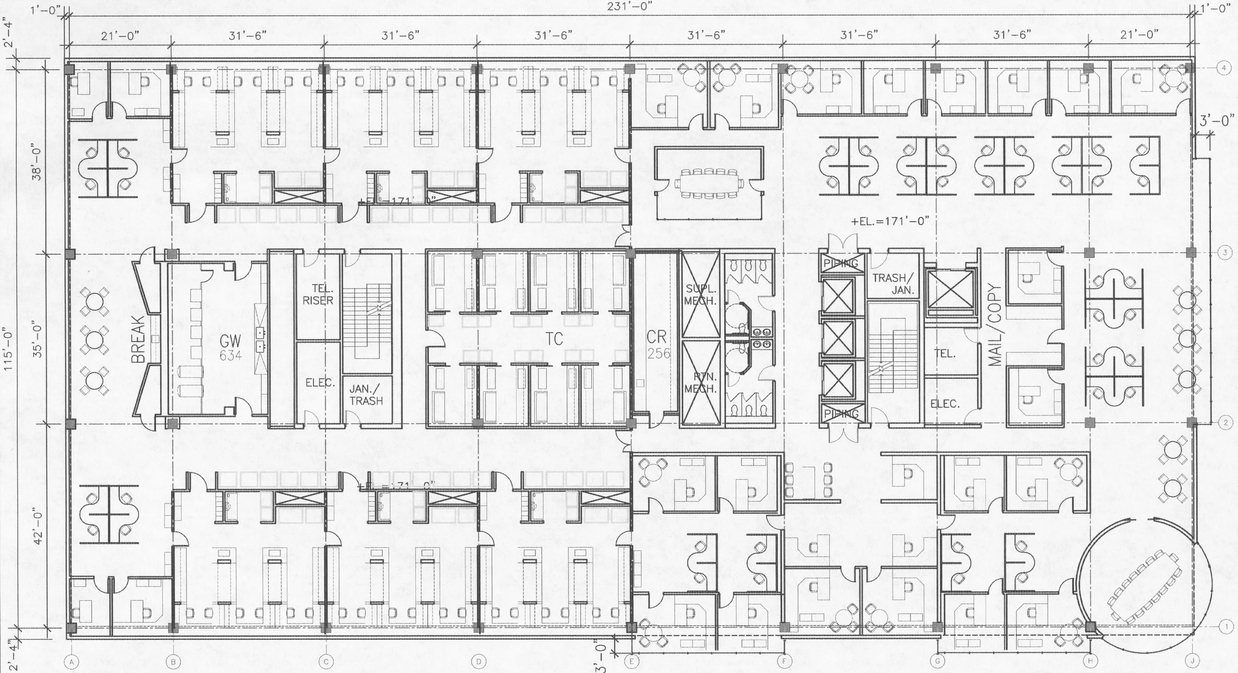
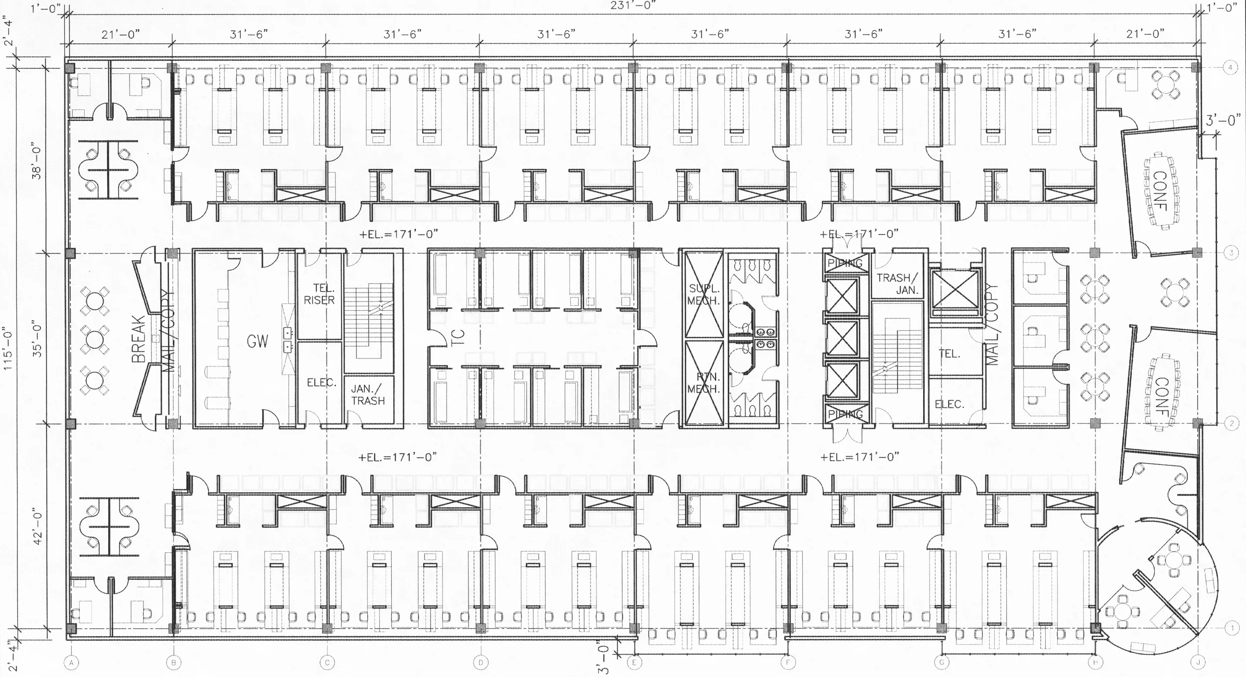
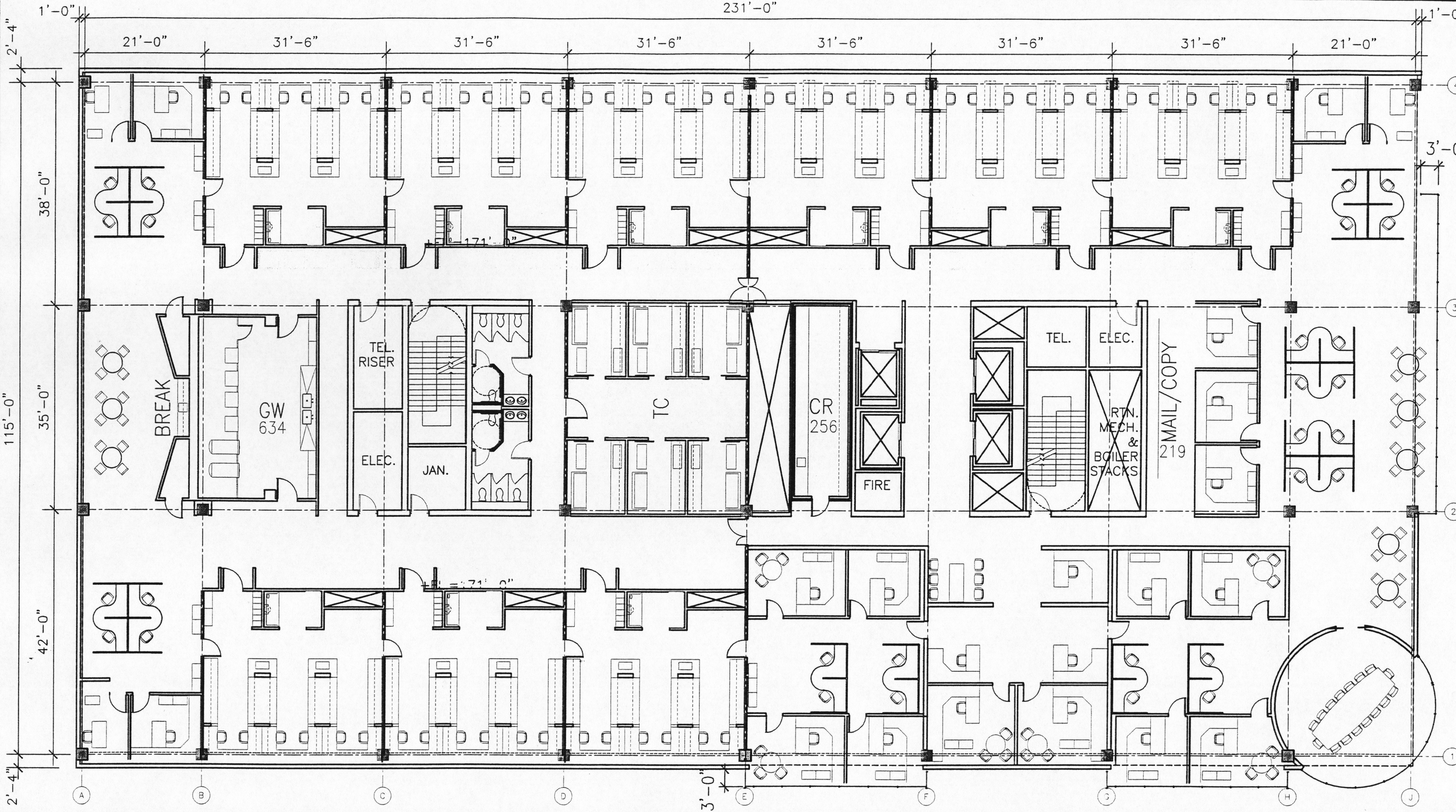
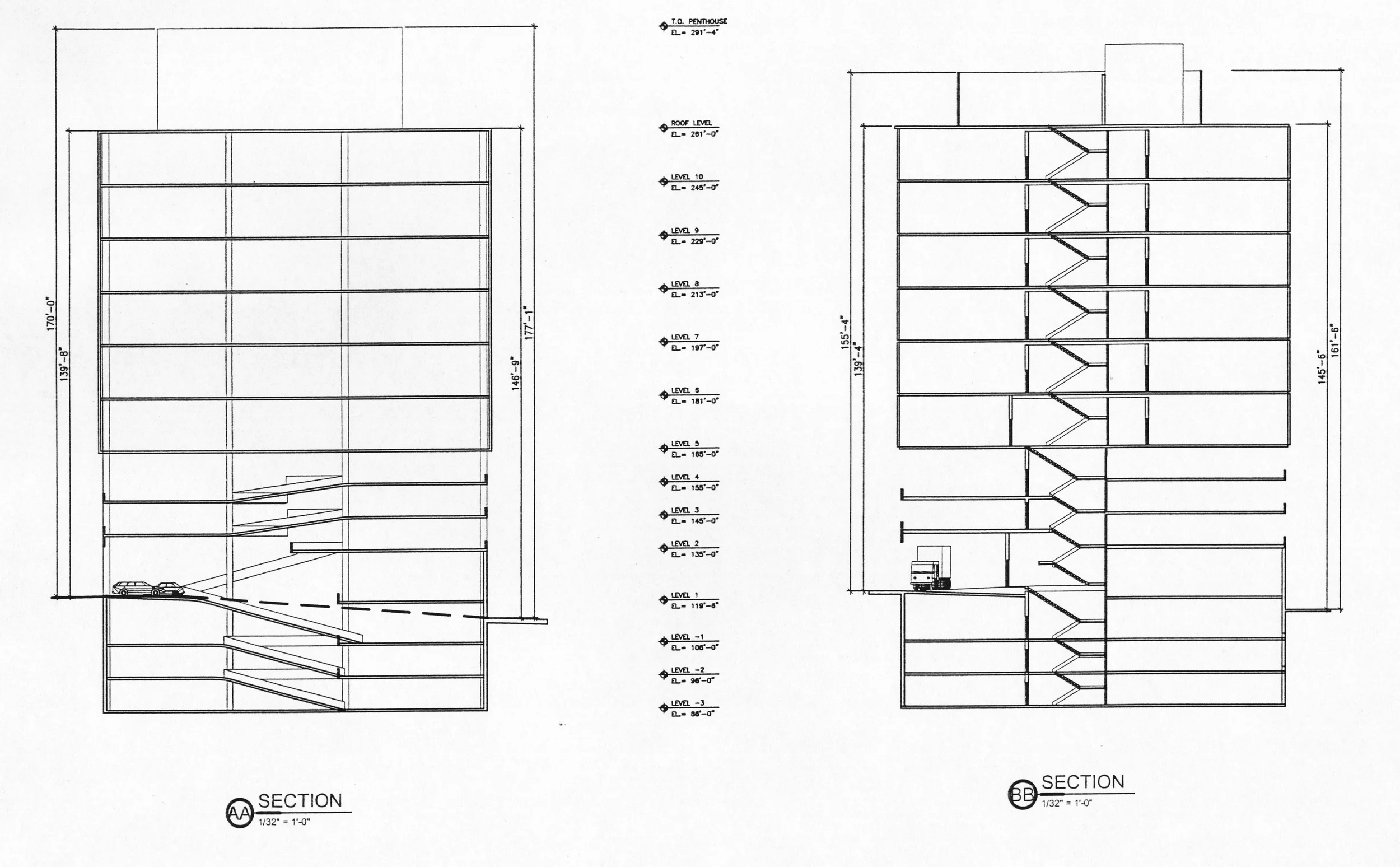
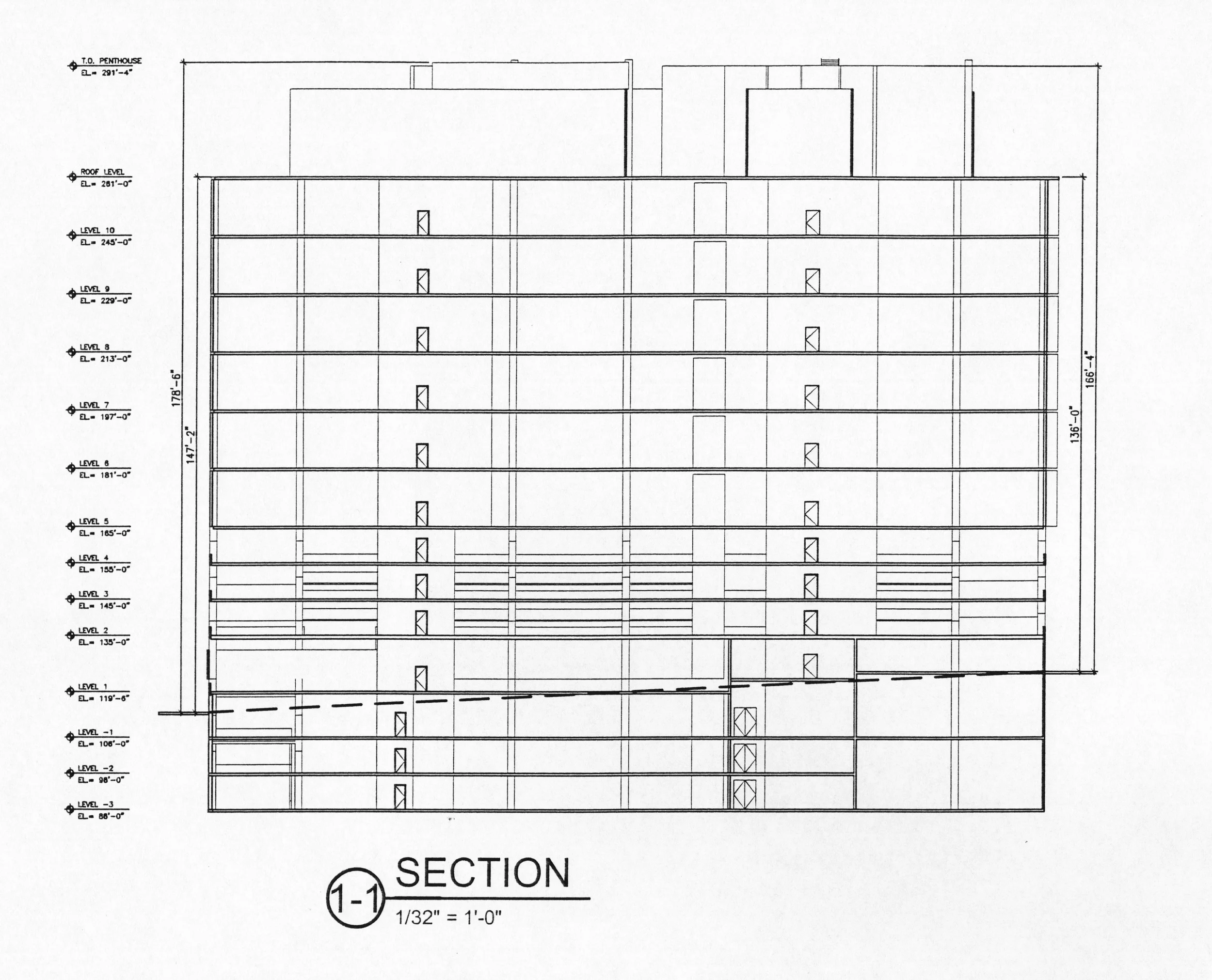
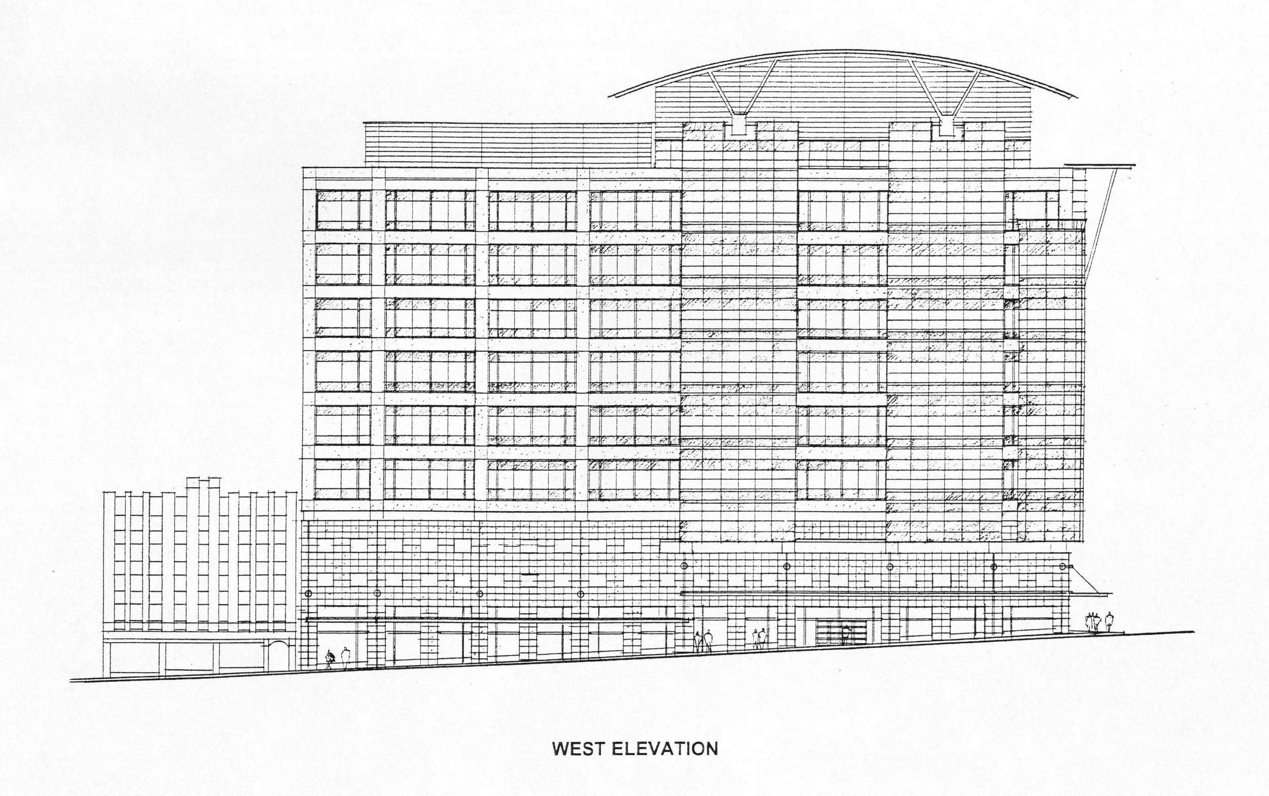
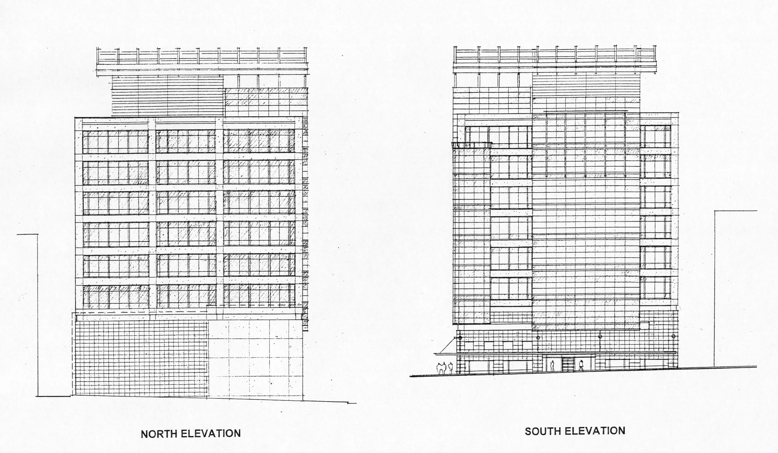
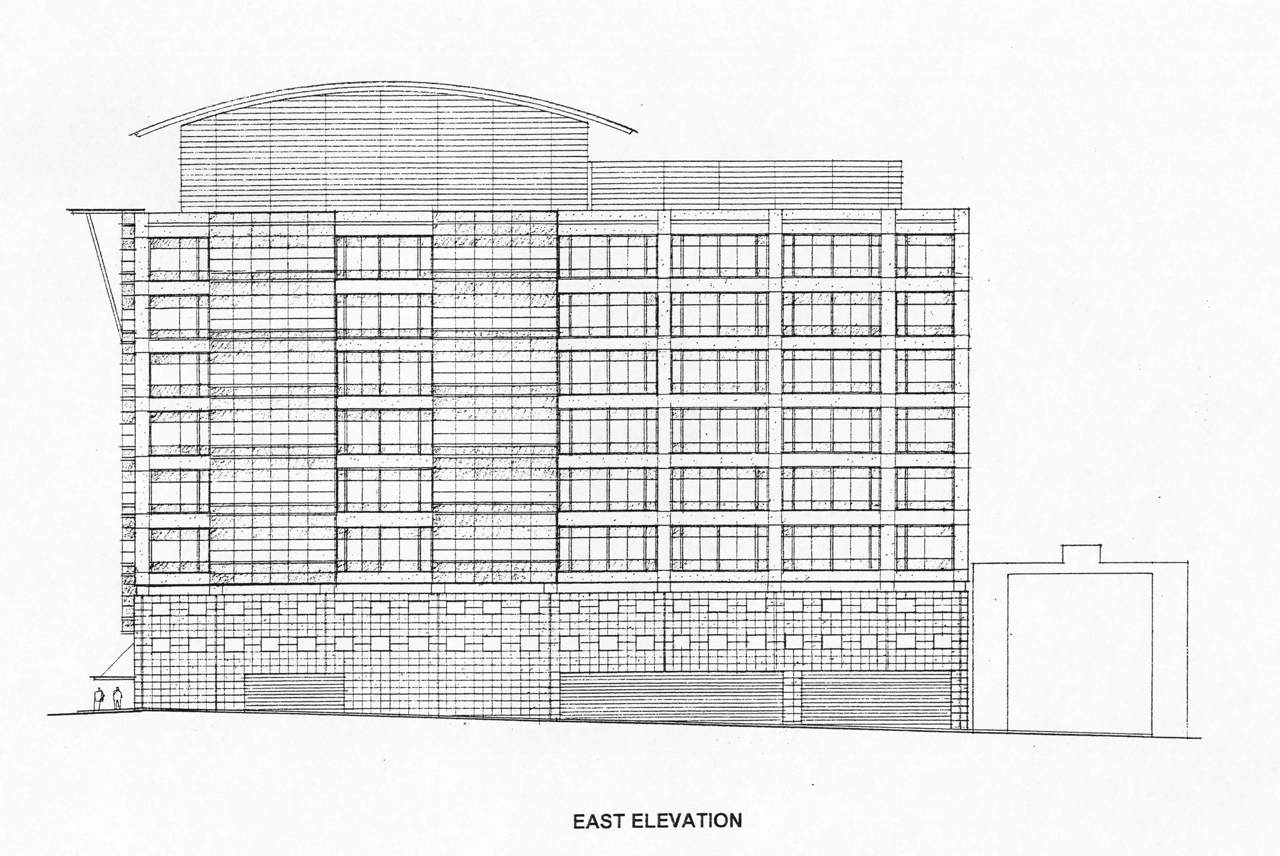
Copthorne Hotel Newcastle for Copthorne Properties
Architecture Firm: Arup Associates
Client: Copthorne Properties
Site: Tyneside, Newcastle
Date of Project: 1988
Project Summary:
Summary: JBM's role on this project in 1988 was: to provide design development support for the fenestration of this riverside hotel together with the principal architect, Michael Lowe. I produced a design development facade study resulting in a package of drawings and models over several facade options and prepared a design development package which was presented to the client.
In 1988 Copthorne Properties, real estate developers of Copthorne Hotel approached Arup Associates architects to provide a concept for a new hotel to be constructed in Newcastle on the bank of the River Tyne.
The project was constructed after this design effort in 1990. The completed building, which finished in 1992 retained all of the original design components.
Specific Role by John Millard: 1) Originate fenestration studies, 2) Part of a team of five architects, JM assisted the team with facade detailing and design. 3) Coordinate Engineering Disciplines, 4) Produce all Design Development Phase Drawings for approval by Owner.

The Hotel was constructed on the east bank of the River Tyne in Newcastle. After the site was excavated, a Roman Wall was unearthed, resulting in an archeological disruption to the project. This disruption caused a delay that enabled National Trust, English Heritage and other more local Historic Preservation Stakeholders to make a determination about the significance of this find. The break in the facade shown in the drawing above occurs exactly where the Roman Wall leaves the river bank and turns due east, through the plan of the hotel.



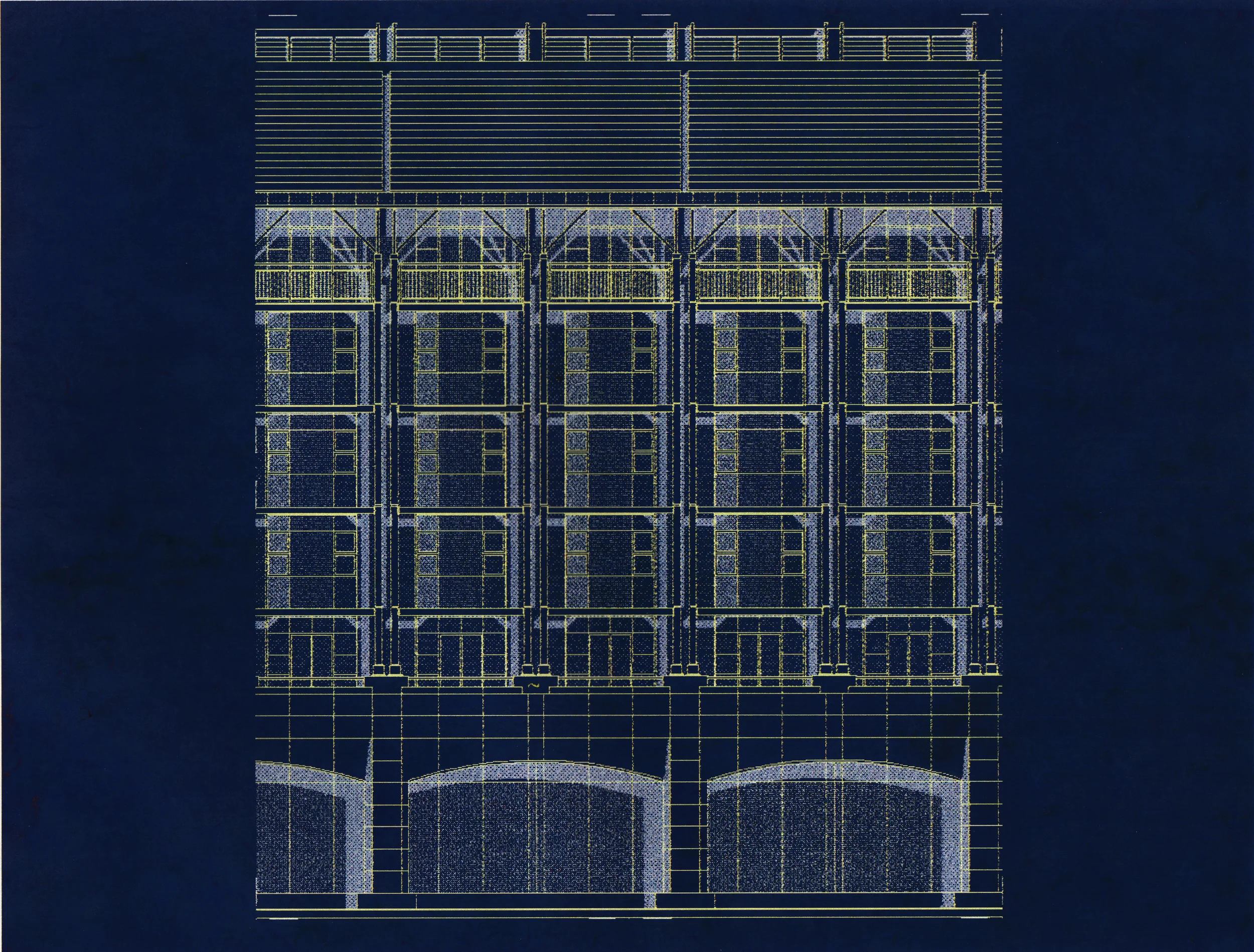
Reebok World Headquarters
Project Summary:
Architecture Firm: NBBJ, Seattle
Client: Reebok International
Date of Construction Completion: June 2000
John Millard's Role: Project Architect for parking structures, walkway canopies and various main building construction details from Schematic Design to end of Construction Documents.
Duration of Design Effort: Schematic Design- October- December 1997, Design Development; January - March 1998, Construction Documentation; April - May/ 1998.
I joined Studio 2 and the Reebok Team just before the beginning of the Schematic Design Phase and remained with the project until the completion of construction documents. During the project, I participated in the formulation of the administration building in the early stages of the schematic design, resolving internal circulation and some work on the connection of the admin building to the spine. This was a brief role in the design of the main building which was cut short by the need for an architect's focused effort to remain engaged on the parking structures which constituted 18% of the construction budget. This role remained my sole responsibility until the end of construction documents. The construction documents are not shown here for security reasons and for the reason that significant "value engineering" measures were implemented by the precast concrete contractor that resulted in the actual construction documents (and the design development documents) becoming superseded. This was due to a budgetary savings opportunity that the owner decided to save on. There were similar overtures by the CM to save on construction budget by simplifying numerous design features in the main building that were resisted by the owner. The parking structures were however simplified and constructed accordingly.




Lab- UCR Biological Sciences






Emerald Street Redevelopment (feasibility study)
Architecture Firm: Arup Associates
Client: The Harpur Trust
Site: Holborn, London
Date of Project: 1989
Project Summary:
Summary: JBM's role on this project in 1989 was: to provide a site analysis of the urban design issues together with the principal architect, Richard Frewer, to produce a schematic design package of drawings and a model and present the scheme to the client, The Harper Trust.
In 1989 The Harper Trust, real estate developers of Emerald Street Development approached Arup Associates architects to provide a concept for a low-rise office building that would be suitable for occupation by Arup Associates.
Initially, Arup Associates had expressed an interest in occupying the proposed development. John Millard had recently completed RIBA Part 1 and was employed by Arup Associates in Group Six. Millard and the Principal-in-charge of the project were the first two architects affecting the initial concept.
The project was shelved after this initial schematic proposal in 1989. The building was never completed.
John Millard's Role-
Role by John Millard: 1) Originate all Schematic drawings, 2) Part of a team of two architects, JM assisted the principal in charge of the design, 3) Coordinate Engineering Disciplines, 4) Produce all Schematic Phase Drawings for presentation and approval by Owner, The Harper Trust
Project was mothballed in 1989 and not constructed to date.
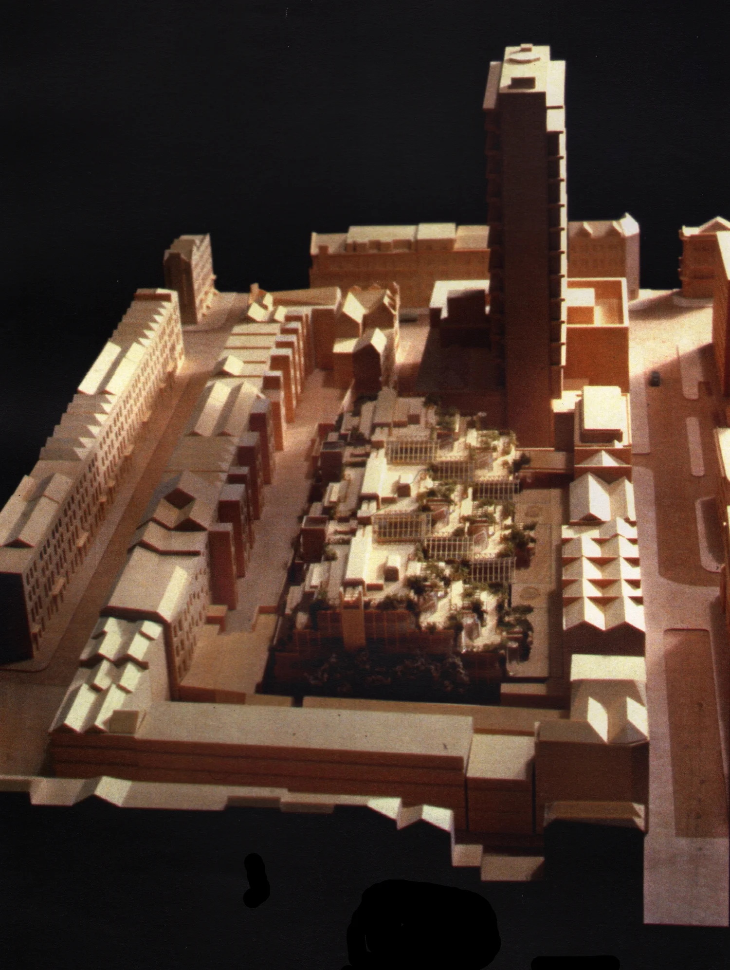
When I was a new student at the Architectural Association School of Architecture in 1984, I was required to register with the Holborn office of the Metropolitan Police (tall building in the background of the model above) as a resident alien. Five years later, I was privileged to join Unit 6 at Arup Associates and work on a redevelopment of this urban context which included the closure of a mews adjoining the Police Station in Holborn where I registered as a resident alien. (Model by Arup Model Shop)

The building was intended to become the new offices for Arup Associates and the height restrictions related to Rights of Light easements among other height restrictions lent the project to a modest floor to area ratio suitable to the Arup Office Culture. (Drawing by John Millard)

The existing urban context shows the road that would have to be closed, buildings that would have to be demolished in order to construct the proposal shown above. (Model by Google Earth)
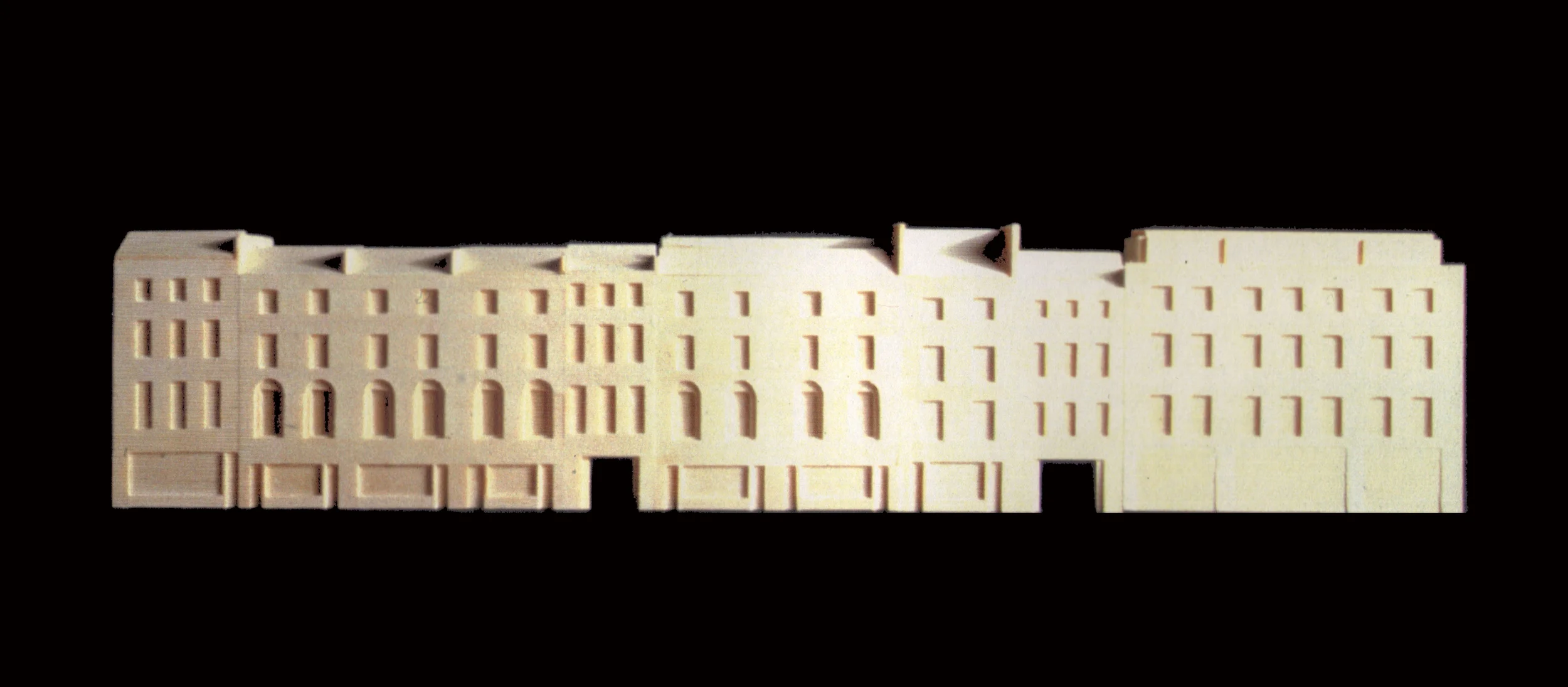
The ground floor openings shown on the model are the pedestrian entrances to the development and coincide with the Entrance Atriums in the Emerald Street Development. (Model by Arup Model Shop)
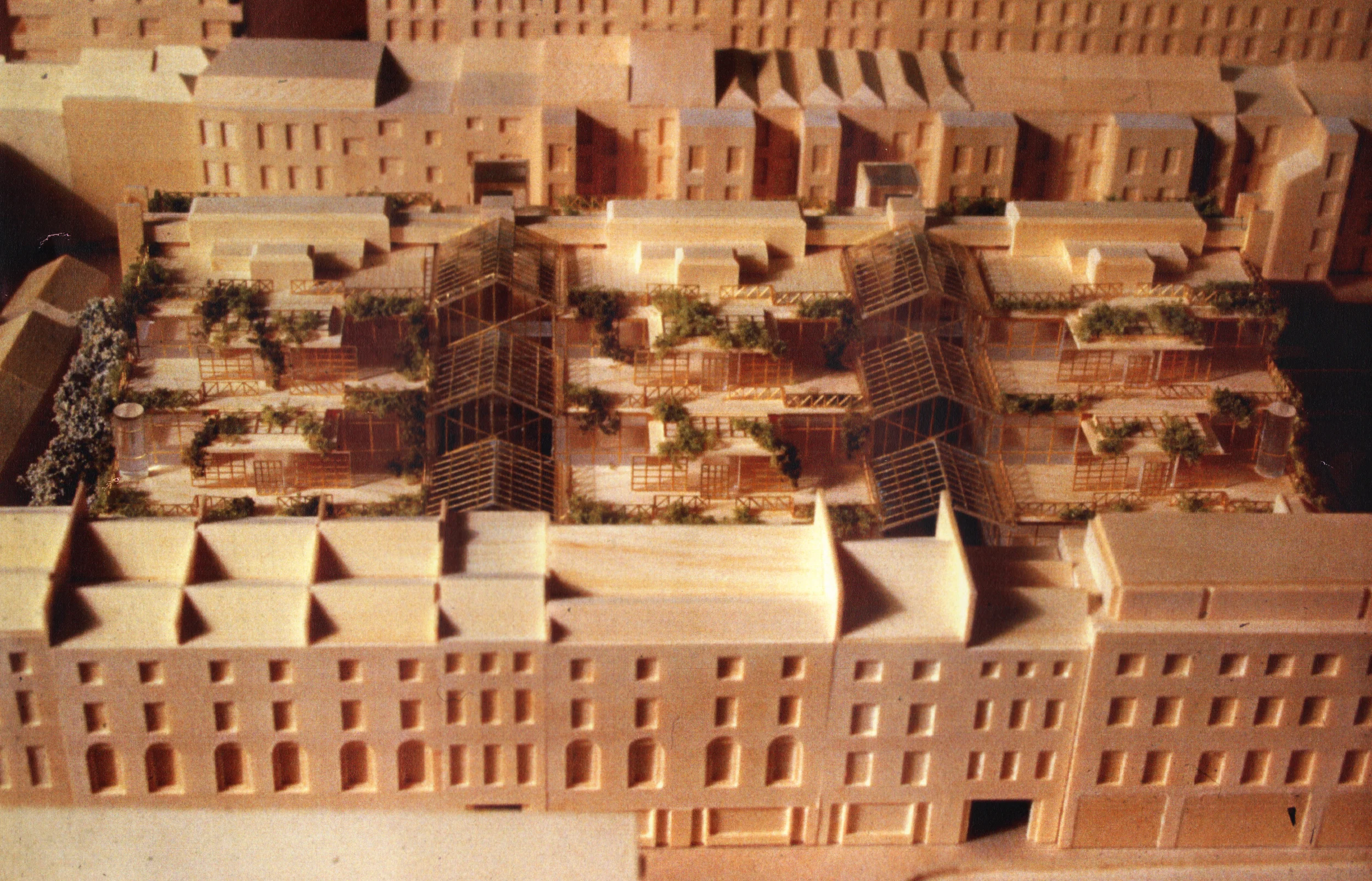
The model demonstrates the discrete presence that the Emerald Street Project has while tucked away behind the foil created by the Georgian Era Terrace Houses. (Model by Arup Model Shop)
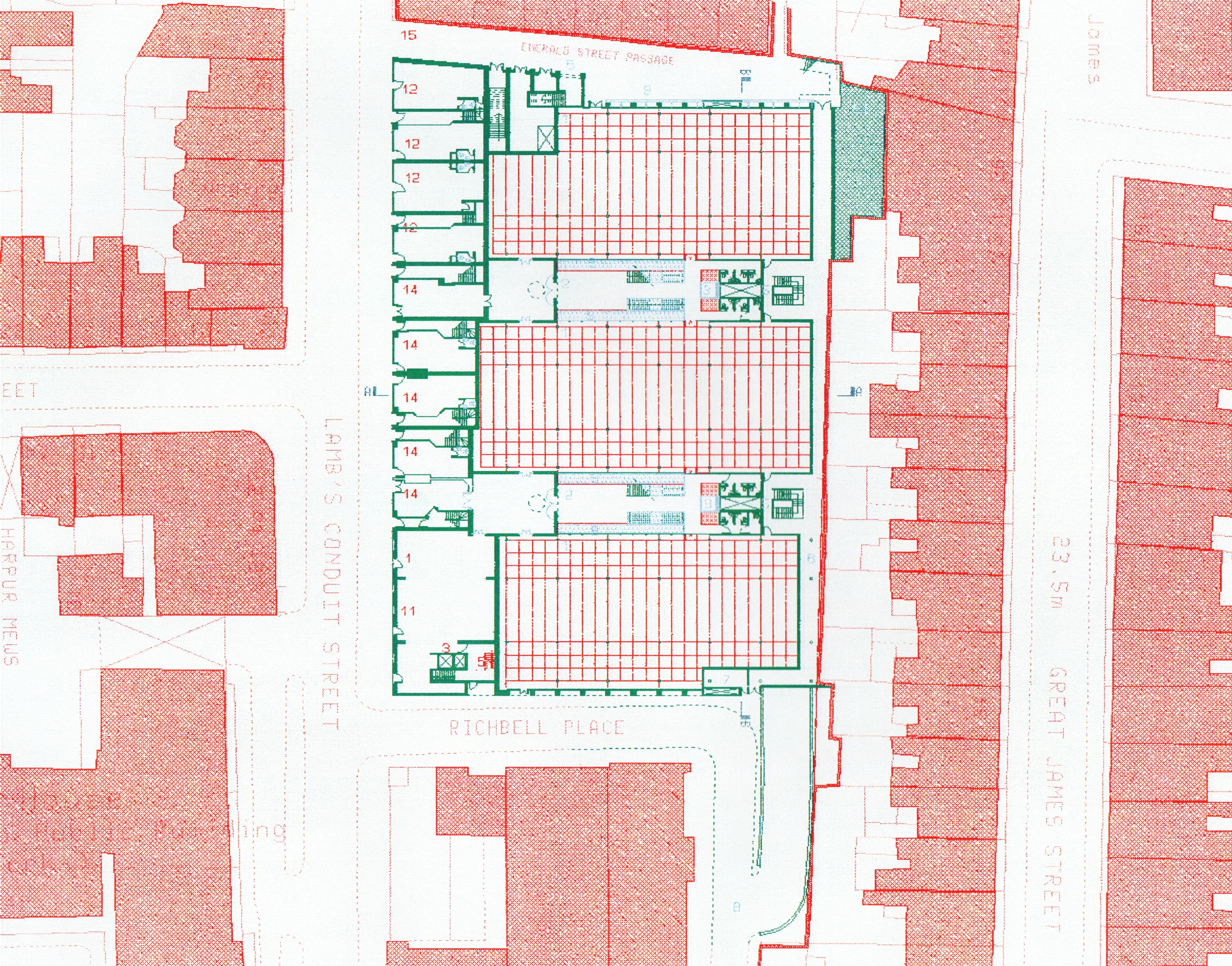
Drawing shows various entrance points for pedestrians and vehicles as well as means of escape route from stair cores and ground floor occupancies. (Drawing by John Millard)
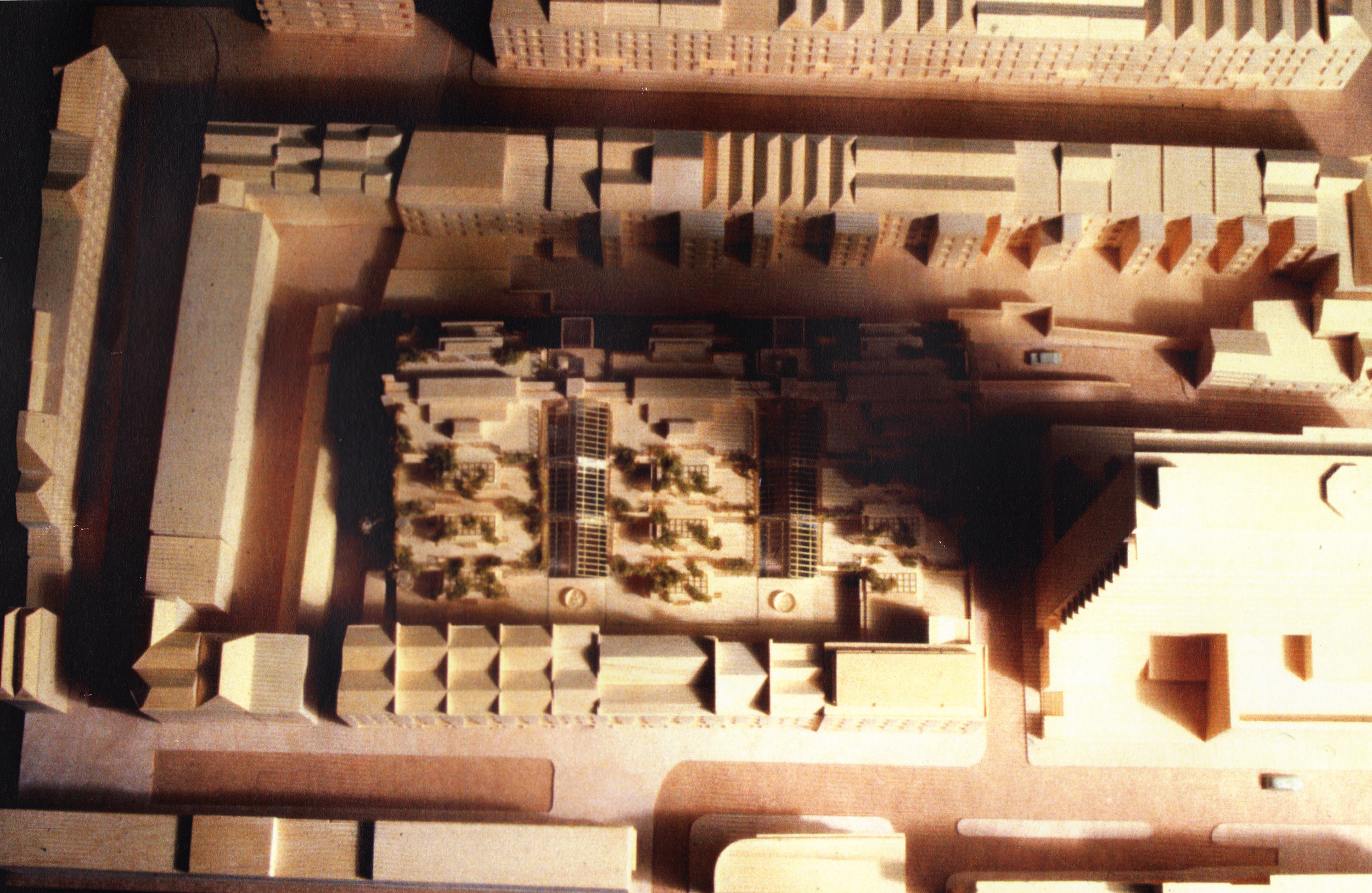
The shadow of the existing Police Tower on the proposed development.was not a development constraint for the police station but was certainly a constraint for the Emerald Street Development. (Model by Arup Model Shop)
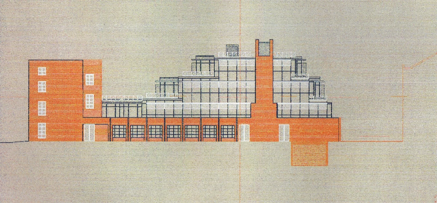
Materials: Red Brick, Steel & Glass (Drawing by John Millard)
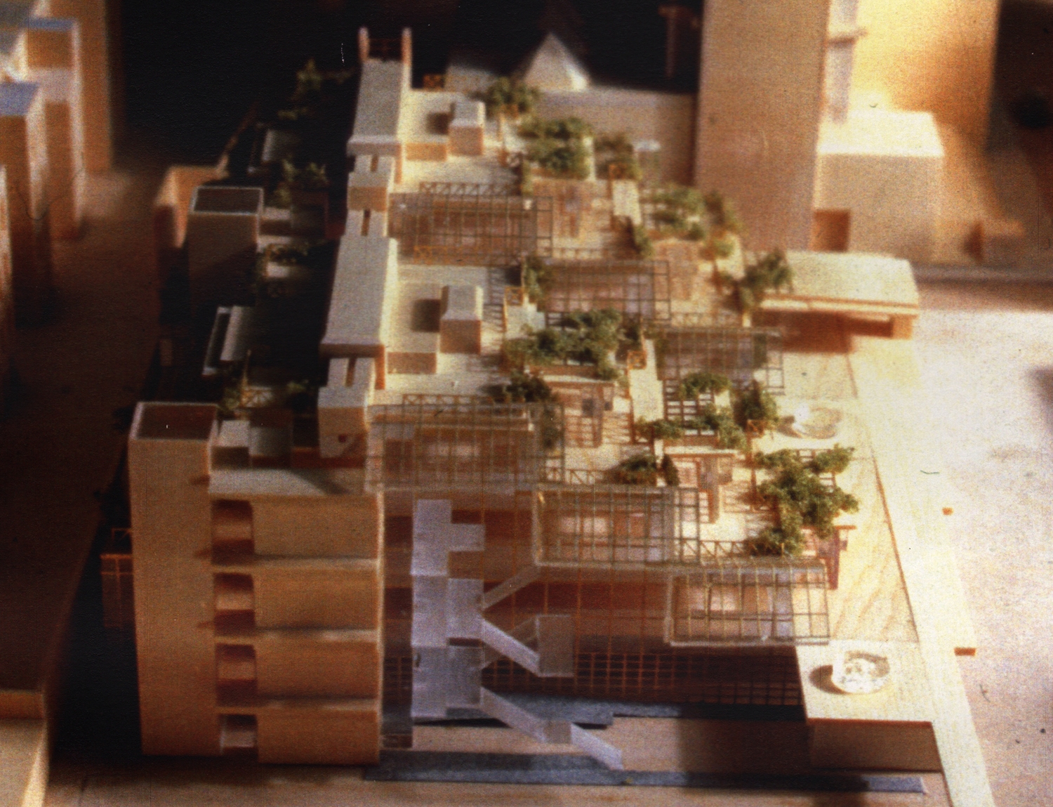
The three building structures form two voids that are opportunities for entrances that were cultivated as atriums with glass canopies and elevator shafts that frame the staircases. (Drawing by John Millard)
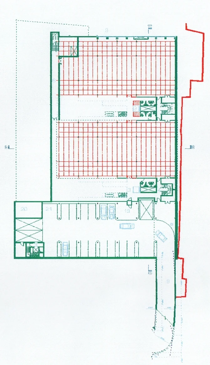
The significant additional gross area available in the Lower Level Plan, and the ability to deliver natural light to this level from the two atria at ground level- tipped the efficiency of this project into the "feasible" category when reviewed by the client. Even minimal, on site parking also added value to the mixture of retail and corporate space. (Drawing by John Millard)
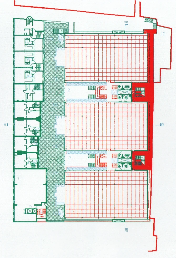
The elevated terrace that formed a garden outside the first floor conference rooms also provides circulation space between the buildings as well as means of escape. (Drawing by John Millard)
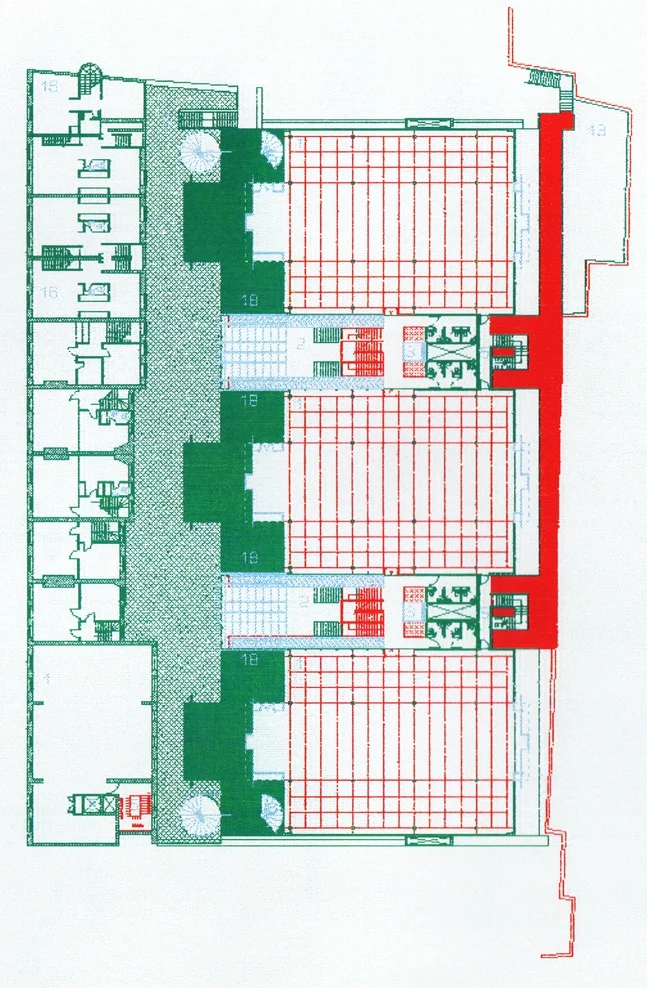
The dark green areas are outdoor terraces that allow for green roofscape and natural ventilation through operable glazing in the conference spaces. Means of escape via code compliant circular stairs at the extreme north and south of the development allow for minimal cores. (Drawing by John Millard)
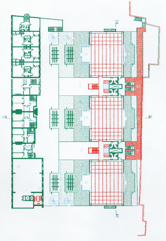
The upper floors are all served with HVAC, Plumbing and Power via the steel service towers that negotiate the transition and distribution of services into the sub-floor plenum where conditioned air and wiring are delivered to each office module. (Drawing by John Millard)
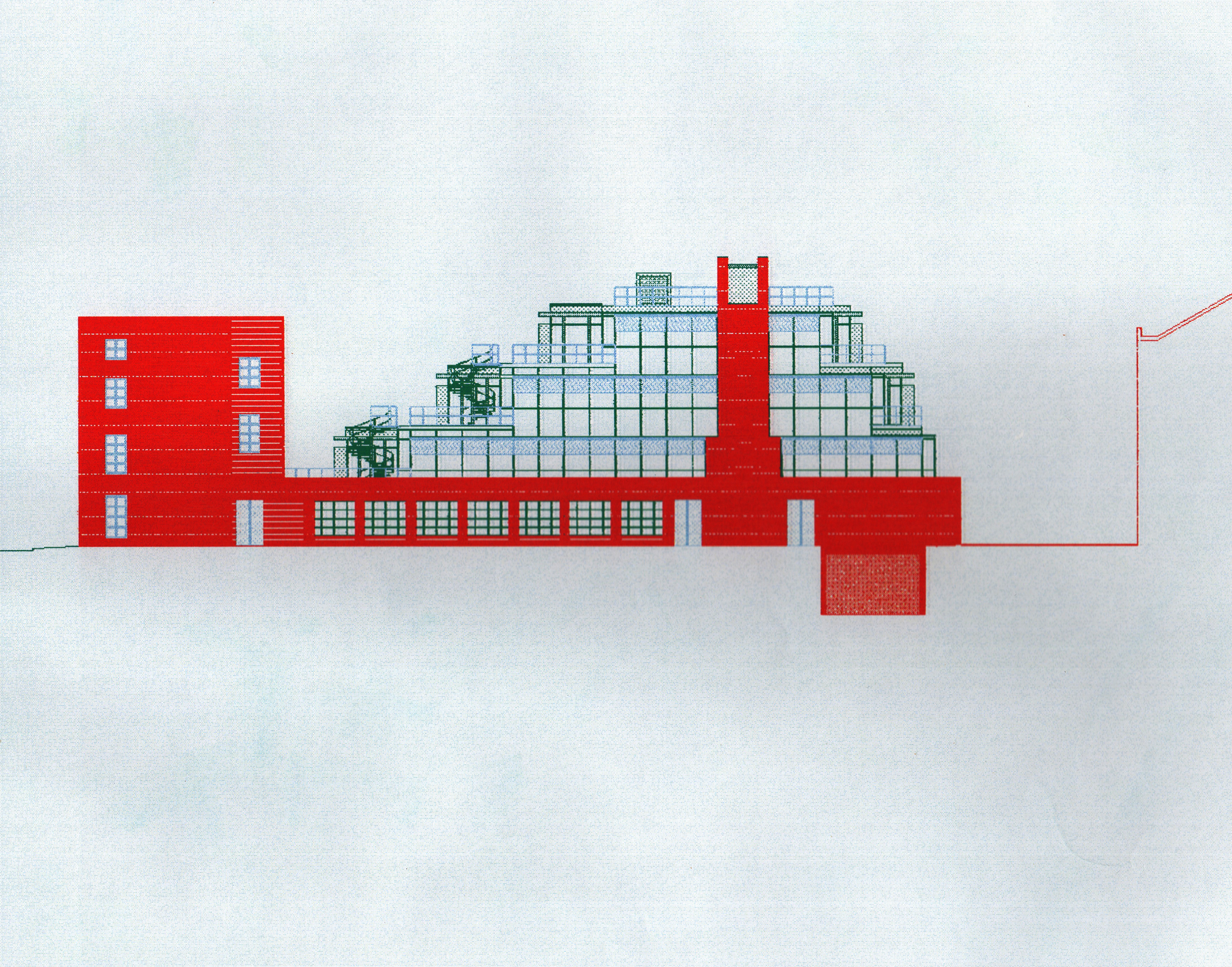
The existing buildings (to be renovated) were owned by the developer and planned to be occupied by tenants of the development. Privacy issues between these buildings were not an issue for these previously residential terrace homes. (Drawing by John Millard)
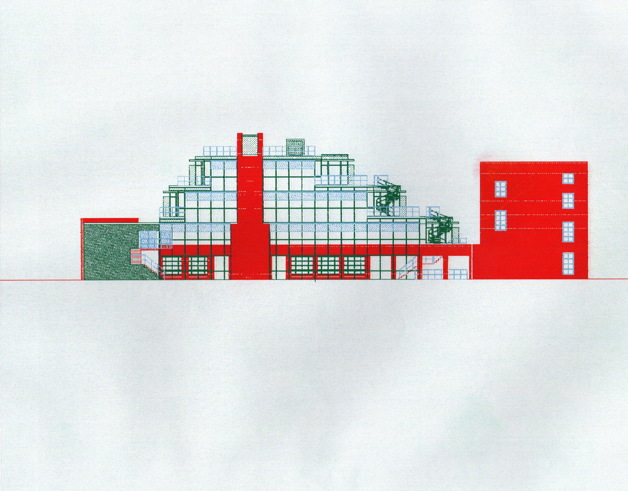
The North Elevation shares a common exterior with a passageway that serves as a pedestrian access/ egress to and from the north.
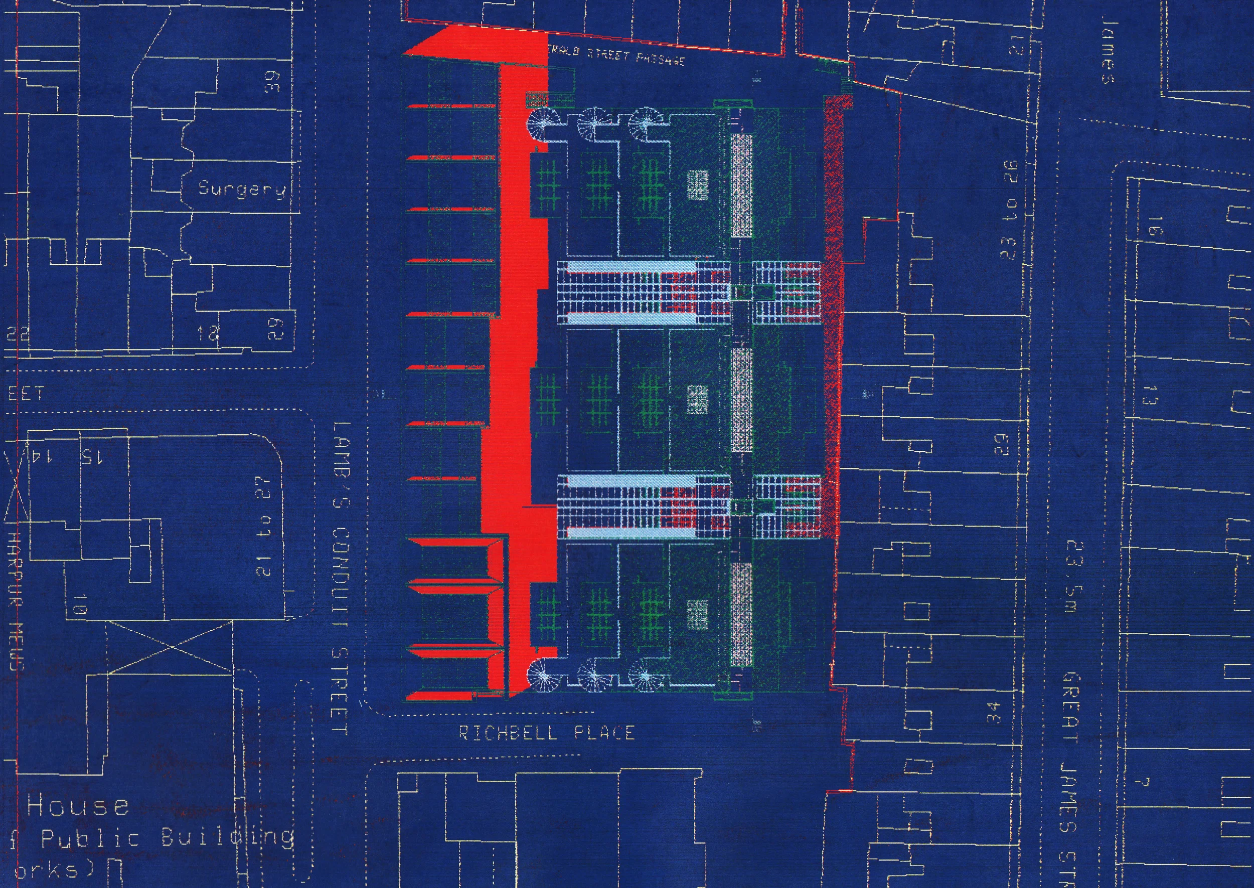
Arup trained John Millard to use the software by McDonell Douglas Information Systems to import Ordinance Survey Maps into he drawing environment and produce accurate site plans, sections and elevations of the project in 1989.


