Beekeepers' Institute Site and Landscape Strategy
Planning of the Beekeepers Institute is part of a group of institutions inside of the now disused Crystal Palace Park. In addition to the beekeepers, there are several other interest groups that use the vestiges of the Crystal Palace Park as a location for their activities. These activity groups include the following;
-The British Caravaners Society
-The Crystal Palace Foundation
-The British Botanical Society
-The British Paleontologists Society
-The British Race-car Association
-The Sports Exposition Authority
-The Crystal Palace Exotic Animal Petting Zoo
-The British Railway Museum
-The British Anglers Society
-Roseberry's Fine Art
There is also a lengthy list of park features that are considered by many to be institutions in and of themselves;
1. Grand Central Walk: Originally 2,660ft long, 96ft wide and linking up to the Palace building, the Grand Centre Walk now only extends up to the steps of the National Sports Centre. During the Festival of Empire in 1911, three-quarter size replicas of all the principal Parliament buildings were reconstructed at this point on the Walk.
2. Old Cricket Pavilion: A late 19th century building stood on this site until 1960. It was used by the famous cricketer Dr WG Grace (1848-1915), who would walk over to play his matches from his home, ‘Parklands’, sited on Crystal Palace Park Road. Dr Grace was player and manager of the London County Cricket Club based at Crystal Palace.
3. H.M.S Crystal Palace: This timber structure and ship’s bell, originally sited on the lower terrace, became affectionately known as ‘HMS Crystal Palace’ when it was occupied by 125,000 men during the First World War. A tablet records its unveiling by the then Prince of Wales in 1931.
4. Airpowered Railway: During 1864, TW Rammell opened an experinlental 600-yard pneumatic or air-powered passenger-carrying railway between the Sydenham and Penge entrances. It was operated by a steam engine, which blew or sucked the train along the track. The 50-second journey cost 6d (old pence) and the single carriage held a maximum of 35 passengers.
5. The Vale: A former Neo-Gothic villa named ‘The Vale’ occupied this site from 1880 until it was demolished and became overgrown after 1977. In an attempt to recreate its former grandeur, the railings have been put back and the frontage walls re-built using most of the original bricks.
6. The Race Track: Until 1973, the former motor-racing circuit was used by such greats as Stirling Moss, Jack Brabham and many others. In 1927, the first motorcycles raced around the pathways of Crystal Palace and, in 1953, a new Crystal Palace circuit was reopened for motor racing.
7. Football: This is where the first ever F.A Cup Final was held in 1895. In addition to the Cup Finals, the Palace played host to England-v-Scotland Internationals played every four years from 1897.
8. The Maze: The Crystal Palace Park circular Tea Maze is not only London’s largest maze, but also one of the biggest in the country, being 160ft in diameter and occupying a total area of nearly 2000 square yards. It has been fully rebuilt by the London Borough of Bromley as an exact replica of the original that fell into disuse during the Second World War.
9. The Concert Bowl: This area of the park was used as part of the Pageant of London during the Festival of Empire in 1911. The natural amphitheatre created by the landform has excellent acoustic properties. There is an original statue from Crystal Palace in front of the terrace wall, which depicts 'Dante’, the Italian poet.
10. Fireworks and Fun: This was known as the Italian Gardens and was the scene of many a spectacular display of fireworks. The first display took place in 1865 and continued up until 1936, becoming world renowned by the turn of the twentieth century. The current-day fireworks are centred around a grand November 5th public display in aid of charity.
10a. Orangery/North Wing: This repository for an orange grove, known as the Orangery, was constructed in 1854 as an annexe to the North Wing. The structure was finally demolished in the early 1950’s. The original wall to the Orangery can still be seen, the archway being part of an entrance into the greenhouse area.
11. Paxton’s Bust: Donated by public subscription and unveiled at a Fete in June 1873, this was to mark the 20th year of the Palace and to show appreciation for the master architect. The bust originally looked towards the Palace building over the central pool (now the car park) but has been re-sited and turned to survey the park.
11a. Italian Terraces: The retaining wall, steps and other features of both upper and lower terraces survive largely intact and are Grade II listed. There were statues on each of the plinths depicting the national dress from countries of the Empire, of which one remains intact. The Sphinxes on the Upper Terraces were copied from an Egyptian original in the Louvre and are made of a brick shell.
11b. South Nave: The South Nave housed the Natural History Exhibition and the splendid "Screens of the Kings and Queens of England". One of the original statues from Crystal Palace (a nymph) now sits where the magnificent Follett Osler’s Crystal Palace Fountain once stood. Thhis was 27 feet high and made of 4 tons of the best quality glass.
12. Museum: The museum is situated in the former Crystal Palace School of Engineering, established in 1872 and the only building left after the fire of 1936. Outside the museum, alongside the base of Brunel’s 284ft water tower, is an original 1852 column. The Crystal Palace Museum, run by an independent trust, is only open to the public on Sundays and Bank Holiday Mondays from 2.00 - 5.00pm.
13. Low Level Railway Station: The line and station were specifically built for the visitors to the Palace and grounds, and were opened on the 10th June 1854. The Crystal Palace look-alike station operationally replaced the old building in 1986.
14. South Basin Pool-Water Features: The South Basin Pool, which now houses flamingos, is the last surviving element of Paxton’s extensive water displays. The area of the National Sports Centre to the left was where the lower basin was situated. The water basins supported two 250ft high fountains and, originally, there were over 100 miles of underground pipes using 120,000 gallons of water per minute supplying 11,788 individual jets.
15. Geological Strata-Paxton Bridge: As part of the Victorians’ love of Education, this area of the park was reserved for ‘Geology and Inhabitants of the Ancient World’. The original cliffs included mountain limestone, millstone grit, ironstone and new sandstone. To the left was a model of a Derbyshire lead mine, complete with pipe veins, rake veins and stalactites and with life-size models of Irish Elks above the entrance.
16. Prehistoric Monsters: The prehistoric monsters, 33 in total, were built in 1854 under the guidance of Professor Richard Owen, who invented the word ‘dinosaur’. These first-ever full-size dinosaurs were created by Benjamin Waterhouse Hawkins, an expert on geology and extinct animals, who constructed the models based on fossils kept in the British Museum. It is now known, however, that many errors were made, especially in Owen’s masterpiece, the Iguanodon. The Iguanodon's rhinoceros-type horn located on the its nose was, in fact, a kind of spiky thumb.
17. Boating Lake: Constructed as the lower reservoir, the boating lake was also known as the ‘Tidal Lake’. When Paxton’s full system of waterworks was in operation, the level of the lake was subject to great changes, being low when water was drawn off to feed the fountains and high when the water was returned. People still enjoy the use of the boating lake to the present day.
Demolition before New Construction- a pattern of practice at Crystal Palace- to be repeated in this proposal to reconstitute park institutions;
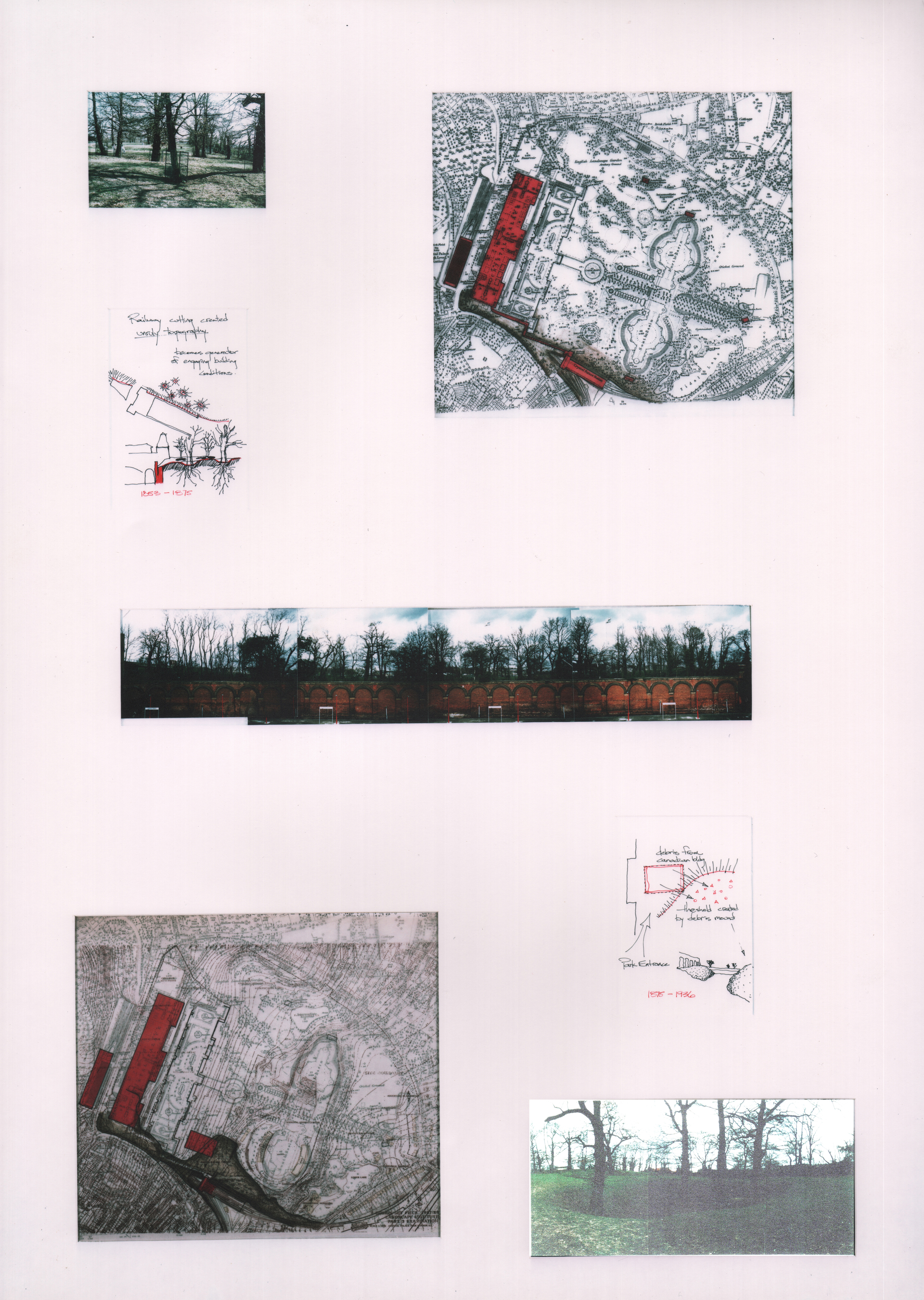
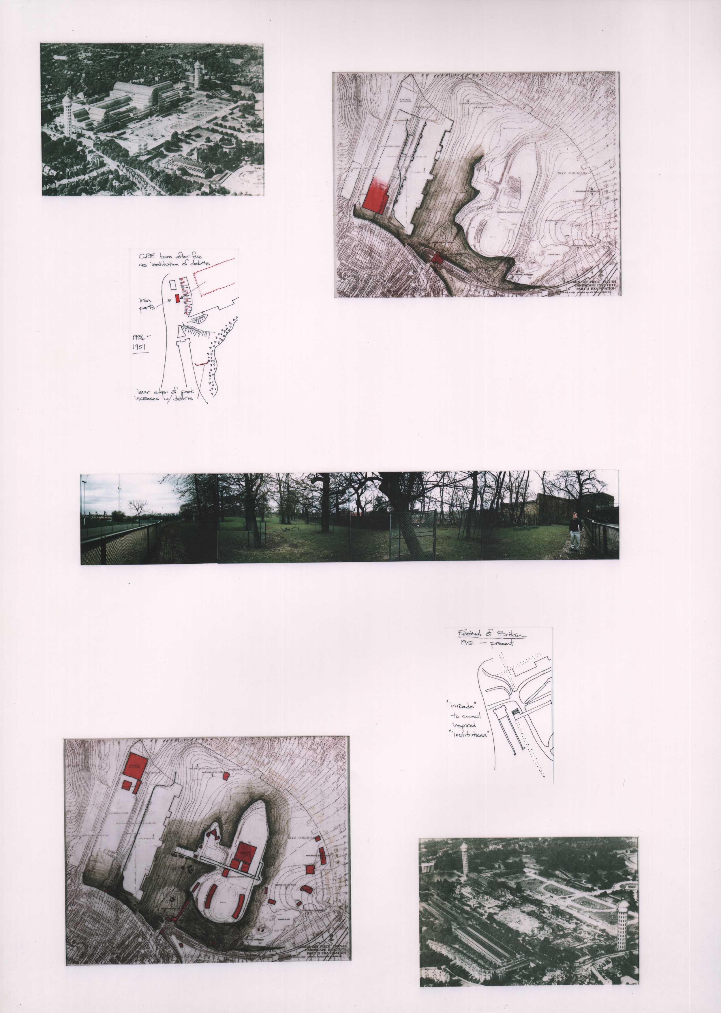
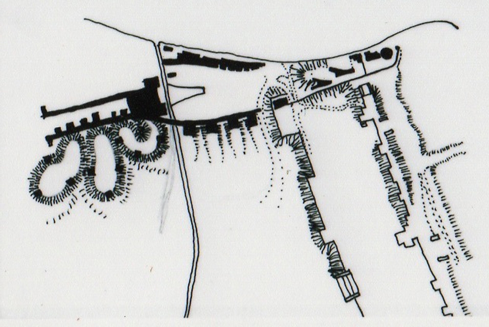
Through the different phases of birth, life, death, burial, rebirth and revitalizations of the park, there has been a common basis of behavior and that has been to deposit fragments of demolition and debris and bury the past under park grounds that is capped with perk-able (sandy) soil upon which grass is grown atop new topography upon topography. While burial of past construction on site in the park may appear to be a convenience by some, the spaces and gateways created by the new topography are poignant and curious.
In reconstituting the park with new landscape and newly constructed institutions listed above, these mounds of debris are seen as rule making opportunity that will help determine the disposition of future construction such as the beekeepers institute. Since additional demolition is required with extensive resulting debris, it is necessary to regrade the existing depositories so that thresholds to the park are defined, opportunities for passers-by to learn about these institutions are taken and the construction is designed to reinforce these goals by retaining the additional landfill, fostering the creation of open space and defining the edge between the park and the community.
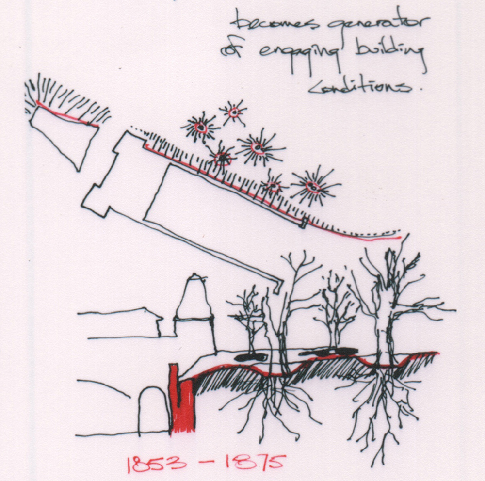
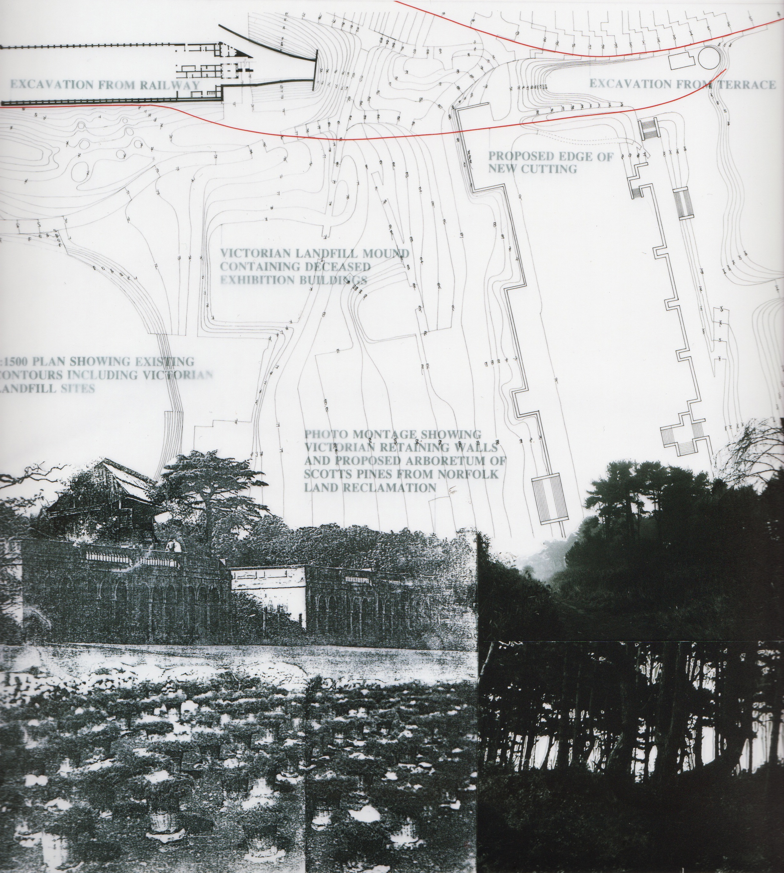
In the photo of the retaining wall (right) constructed to retain park soil that was excavated away from the rail line is an example of edge definition, creation of open space and defining the edge between the community and the park. This wall, which formed a covered space for passenger platforms is all that remains of the Crystal Palace Low Level Station's train shed. This space is the subject of one institutional occupation, namely, The British Rail Museum. While this institution is not the subject of this proposal, the greater goal of creating an institutional edge between the community and the park is material to this aspect of revitalizing the park as a method of revitalization and reinforcement of the strong park edge- a place where community and institution celebrate the park without contaminating it with more freestanding clutter.
This sectional sketch through the Low Level Station's retaining wall with the park is a common feature of railway cuttings. It just so happens that this condition is such a strong element on this southern edge of the park that other similar retaining walls such as the "Italianate Terraces" and similar conditions at the High Level Station conspire together to dictate rules followed by prior projects. The temporary nature of the Crystal Palace, which was not designed to survive the turn of the century and eventually fell into disrepair provides the converse precedent for what should be free-standing (setting atop the plateaus) and what should be engaging the contours (holding back the chasm).
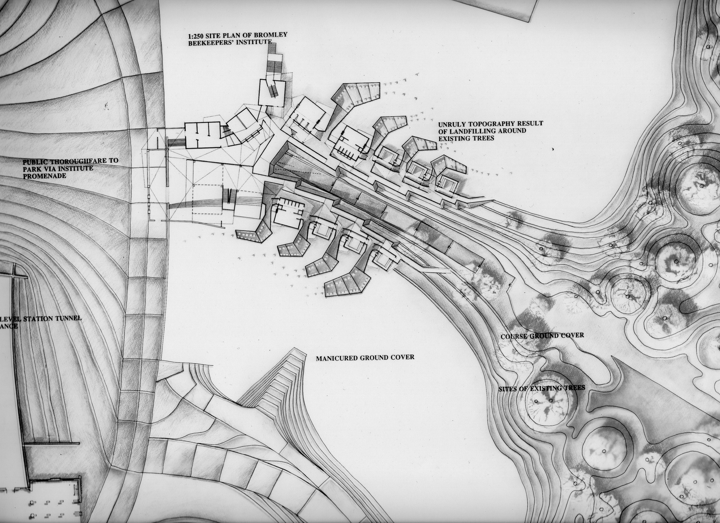
In the case of the Beekeepers Institute, the siting of this project will follow a similar story to the siting of the Low Level Station by Paxton- The presence of the building should facilitate some aspect of access to the park (in this case also access back down to the Low Level Station Tunnel for rail transport and a Trainspotters Cafe (also not the subject of this proposal). The Beekeeper's Institute will also follow the curious rules of accommodating existing deciduous trees within the deposition grading (creating craters around deciduous tree trunks in order to protect them from placement of new debris).
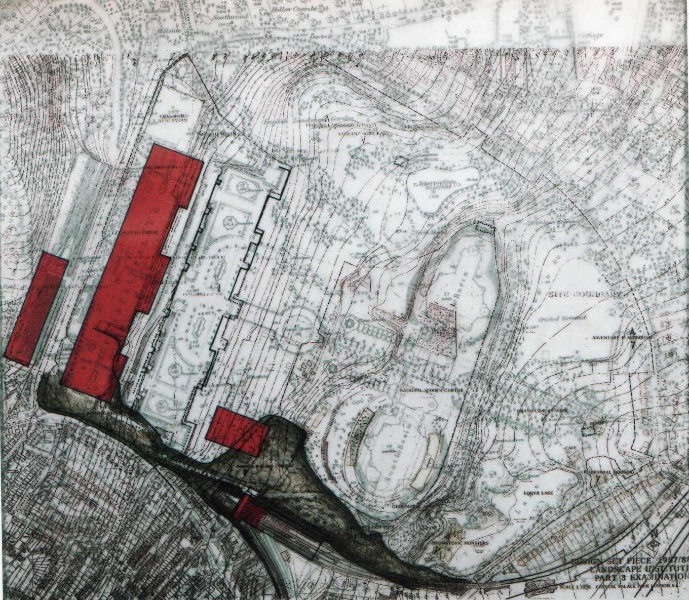
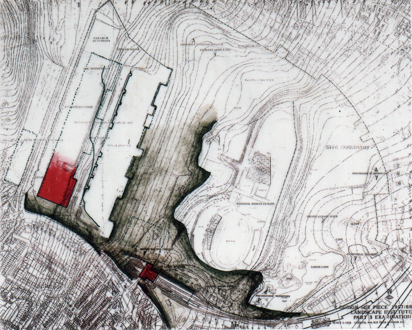
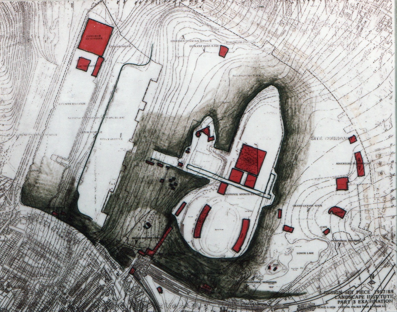
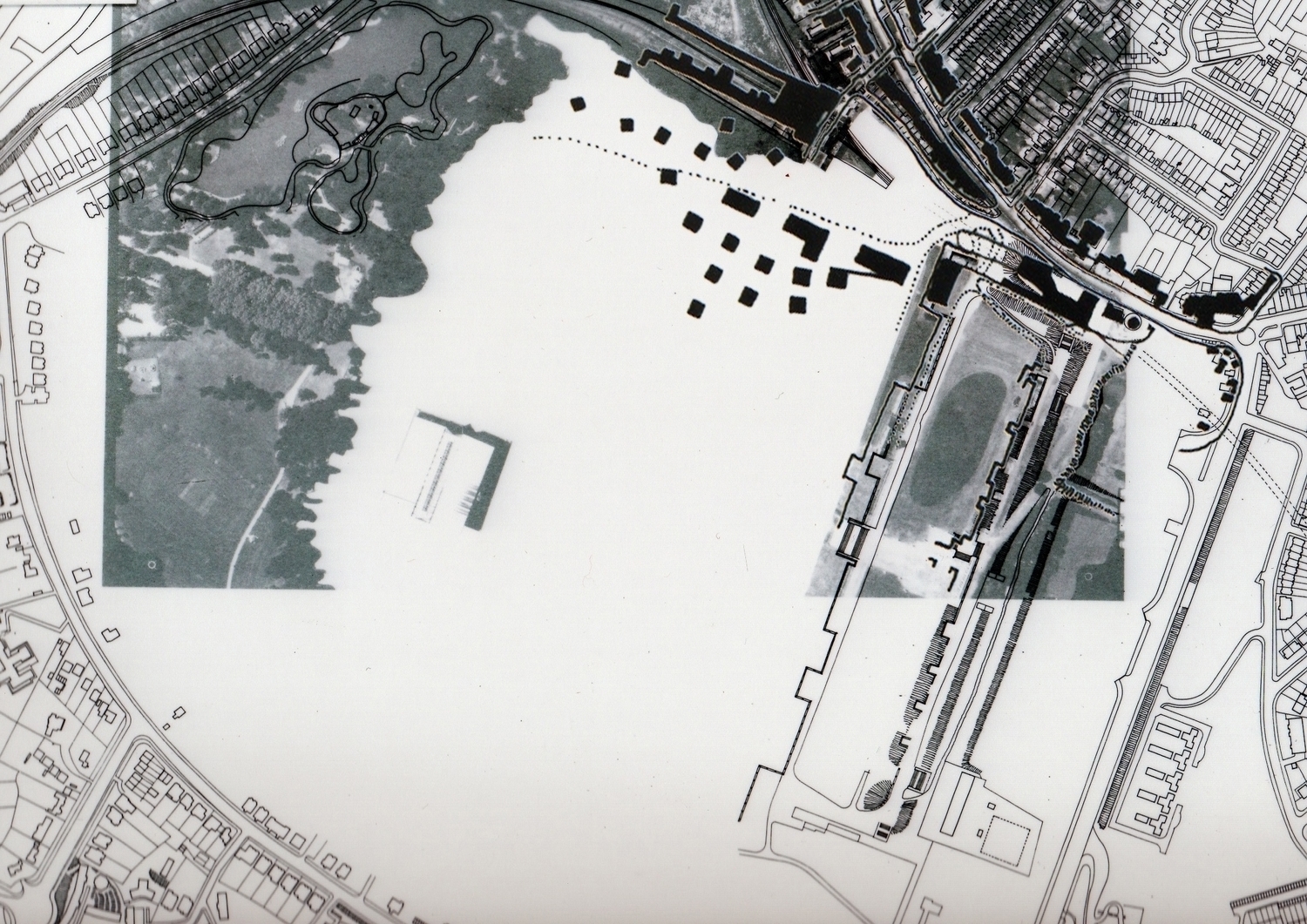
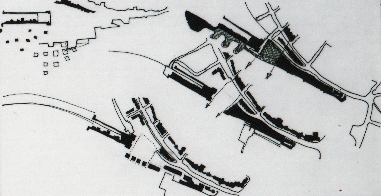
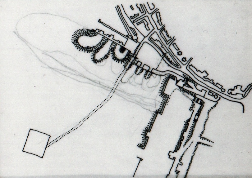
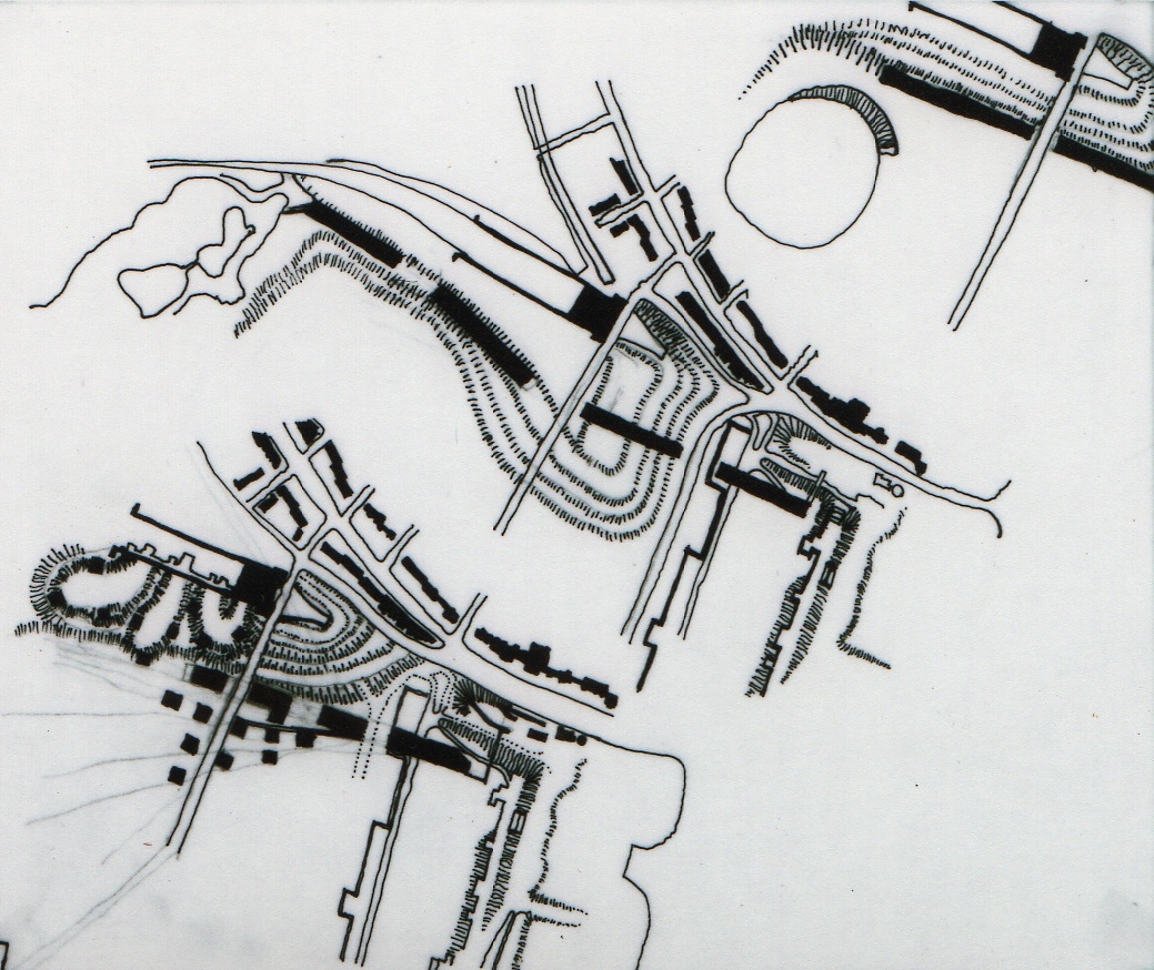
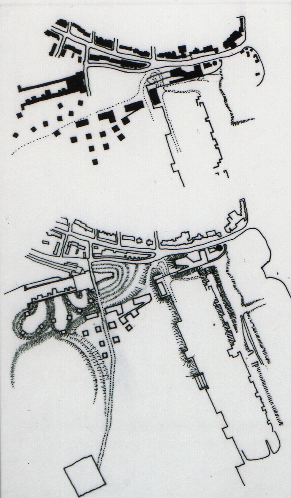
These curious conditions are telling of a possible landscape strategy that could determine tree placement. Since all of the existing trees are deciduous, and grow out of a loamy indigenous soil, they reflect those soil conditions and shall be preserved in a similar manner as the Victorians who moved debris around the park by horse cart and relented from burying tree trunks in backfill. Hence the craters that are visible around Poplar and Tulip Trees that are common to the southern edge of the park. New tree plantings that will be asked to grow in landfill conditions (sandy loam with hardcore and other debris) will reflect those soil conditions and the location of these trees will be determined by a simple fractal that responds to the steepness (more frequent plantings) or the shallowness (less frequent plantings) of the grade in any particular part of the site where topographical change is being driven by deposition of demolition material. After the fire of 1936 that incinerated the Crystal Palace Building, there was hundreds of thousands of tons of broken glass, melted iron, and other non-biodegradable debris that required disposal and burial. The park grounds offered a ready-made dumping ground for this material. The brown shading in the two plans (right) indicate four separate phases of earthwork and landfill operations that occurred over 50 years. By identifying the pattern of repeated demolition deposition, the topography begins to tell a story that bears repeating. By the 1960s, The London County Council took charge of the site and the architects department undertook the task of designing the Crystal Palace Sports Centre. (shown shaded in red, lower right) The local football team plays in the outdoor stadium (scheduled for demolition in this proposal due to structural decay) while the indoor sports facility contains an Olympic Class Swimming Pool and Diving Platforms, indoor racquet sports, basketball courts and many other activities. It should be noted that this building is the only existing building to remain standing in the Crystal Palace Park as a result of this proposal. This is because the architects who designed this building succeeded in creating a destination in the landscape that breaks all of the rules of the park by qualifying as a permanent, freestanding building that has withstood the test of time and is an asset of the community. Other than that, this building is a vintage example of 1960s Brutalism that has won English Heritage Listed Building Status and must not be demolished.
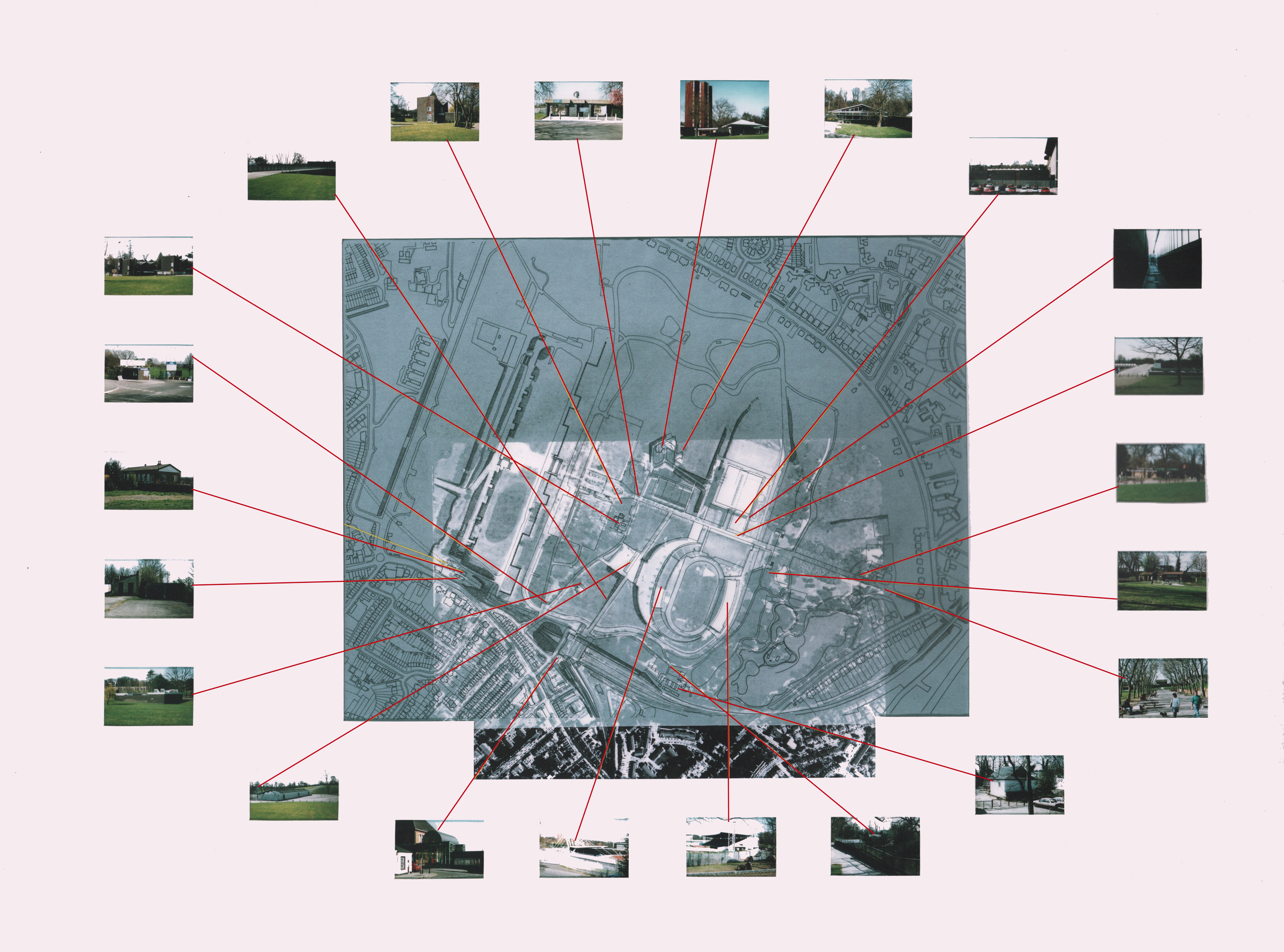
The other 22 buildings that remain standing in the park are scheduled for demolition and are shown on the demolition schedule (right). The debris from demolition of these 22 buildings will be deposited in the park in traditional locations as previously discussed. Identification on the site plan of the dumping grounds is the subject of analysis below.
The buildings shown in this demolition schedule are worthy to be destroyed and their remains should be pulverized into rip-rap of sufficiently small size as to support the growth of Marine Pine root structure. Additionally, the lots vacated by these buildings will be replaced by tree plantings suitable to the soil type and located according to the fractal generated forestation plan discussed below.
Once the site is clear of appurtenances listed above, the 50 acres of clearing leaves only the previously existing trees and the Crystal Palace Sports Centre remaining on the site. The opportunity to reforest the site is secondary to resolving the exact topography that will provide for the disposal of future debris from demolition in such a way as to achieve the previously stated goals of;
a) thresholds to the park are defined
b) opportunities for passers-by to learn about these institutions
c) construction is designed retain the additional landfill
d) fostering the creation of open space
e) defining the edge between the park and the community
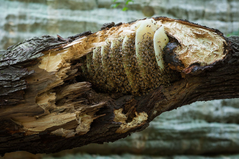
Given these goals, the sketches, the process and the unusual opportunity to design a Beekeepers Institute it becomes important to set the stage carefully for an over-riding metaphor to govern the creation of such an eccentric building. Such a metaphor may lie in the accretion that occurs when a swarm of one hundred thousand honey bees take flight and then choose some hollowed-out tree trunk to occupy as the location for their new colony. The topographical preoccupation understood here may draw some allusions to the interior of that tree trunk and the occupation of that void by the bees.
In exploring the southern boundary of the park, there falls upon the landscape a limit beyond which the streetscape of the community, with it's pavement, roads, curbstones, buildings and signposts give way to the softer textures of the park with it's gravel walkways, grasses, undulating ground and retaining structures. This limit is also informed by the grand space created by the Crystal Palace Low Level Station West Facade. There is also a gaping crater in front of the Low Level Station which is the entrance to the Sydenham Hill Rail Tunnel.
By determining a hard edge to the park, the deposition of debris resulting from demolition of the 22 buildings scheduled for destruction can be dumped up against a retaining wall of core-ten steel sheet pile that contains the debris effectively drawing strength from it and rises above it and becomes perforated by selective oxyacetylene cutting to reveal an evocative motif of marine pines that come to life just beyond.
The Marine Pine thrives in sand. Deciduous Trees thrive in loam. It's that simple. Where deposition of debris has occurred, sand will cover the debris in order to bury it sufficiently below the surface. There you will see Marine pines planted almost exclusively. In some areas you will see both species, Deciduous and Coniferous. Currently there are few, if any Coniferous trees. These Coniferous Marine Pines will grow in such a way as to restrict their foliage to an upper canopy, like a Palm Tree, leaving the lower half of the trunk barren of foliage. Such a species of tree is ideal for walking through a forest of tree trunks, unhindered by low level foliage and affording the forest forager views through the trees to the background topography and buildings in the distance.
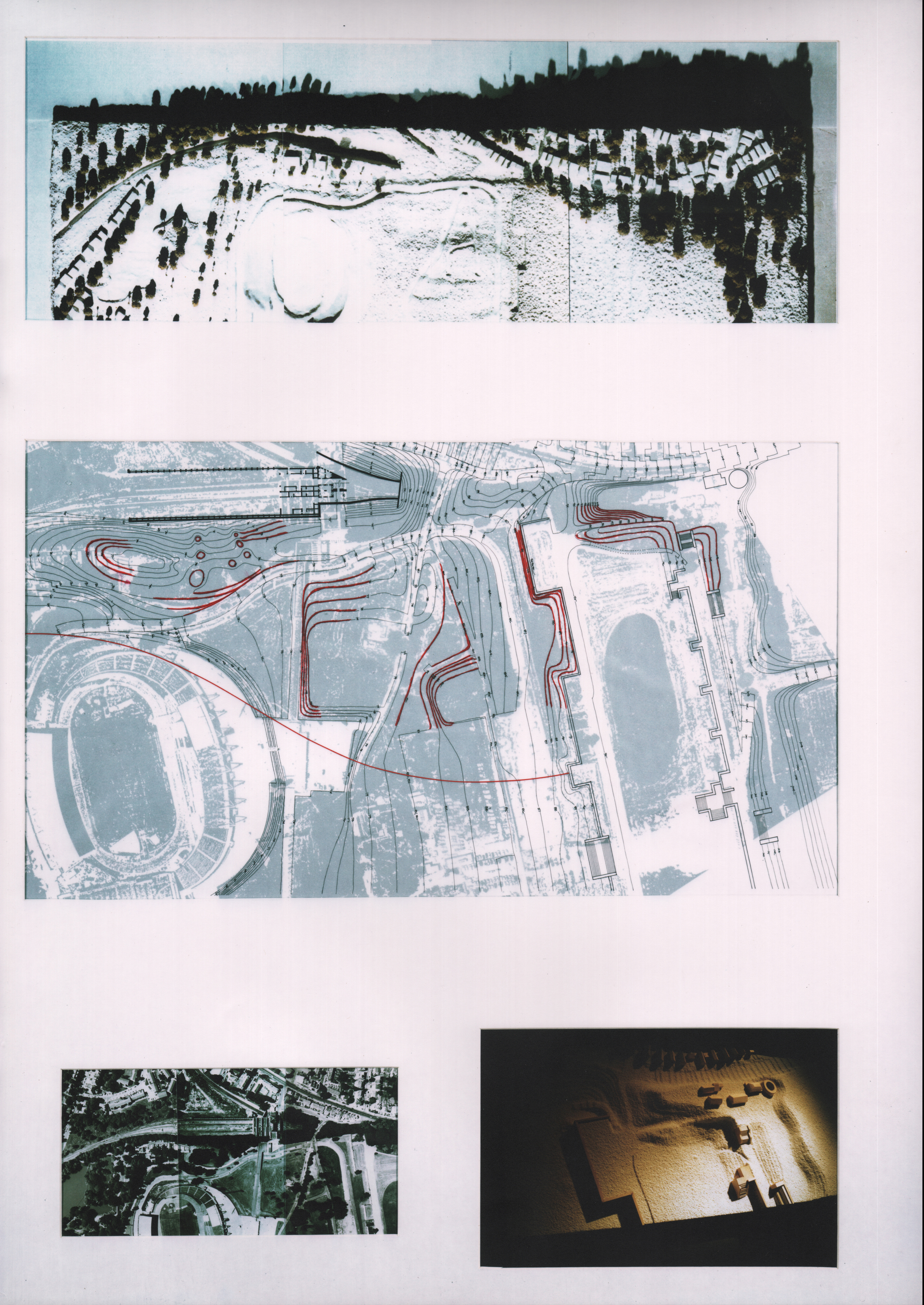
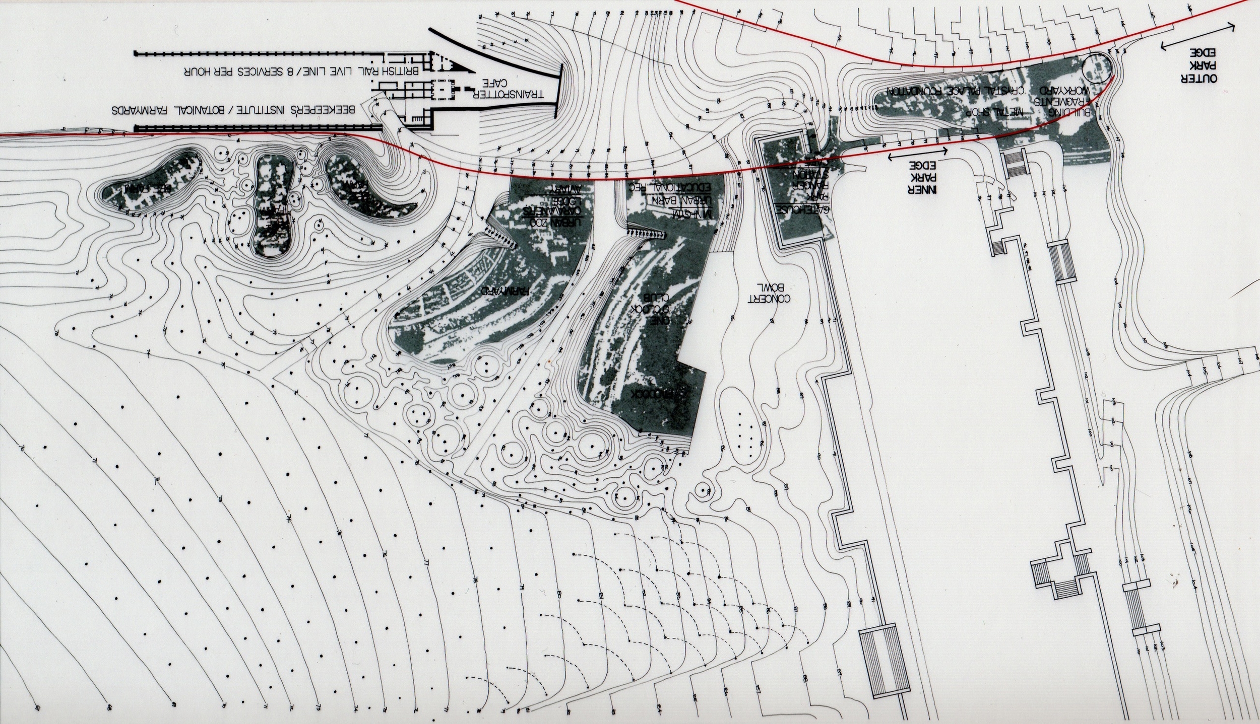
In addition to setting a limit to the park topography with a hard edge, an additional limit, represented by the lowest red line in the plan (lower right) which defines the extent of the "dumping" or deposition of debris from demolition. This edge would be visible in the landscape as the edge of the Marine Pine Forest which grows in the sandy substrate and escalates in planting frequency and slope as the landfill slopes up to the plateaus. Beyond this red line, the newly landscaped park would be replanted with indigenous deciduous Tulip Trees, Chesnut Trees and Oak Trees in addition to the existing trees.
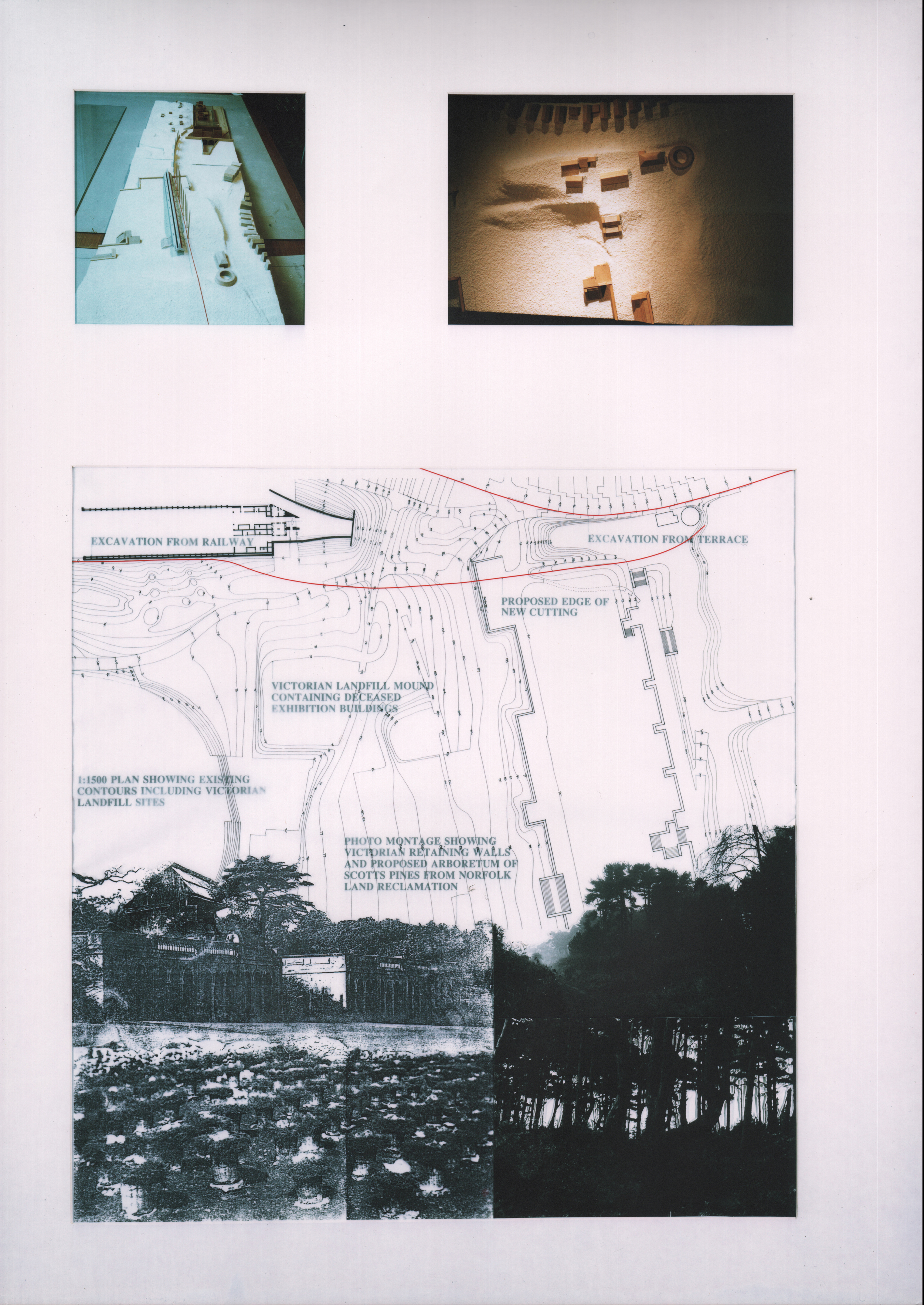
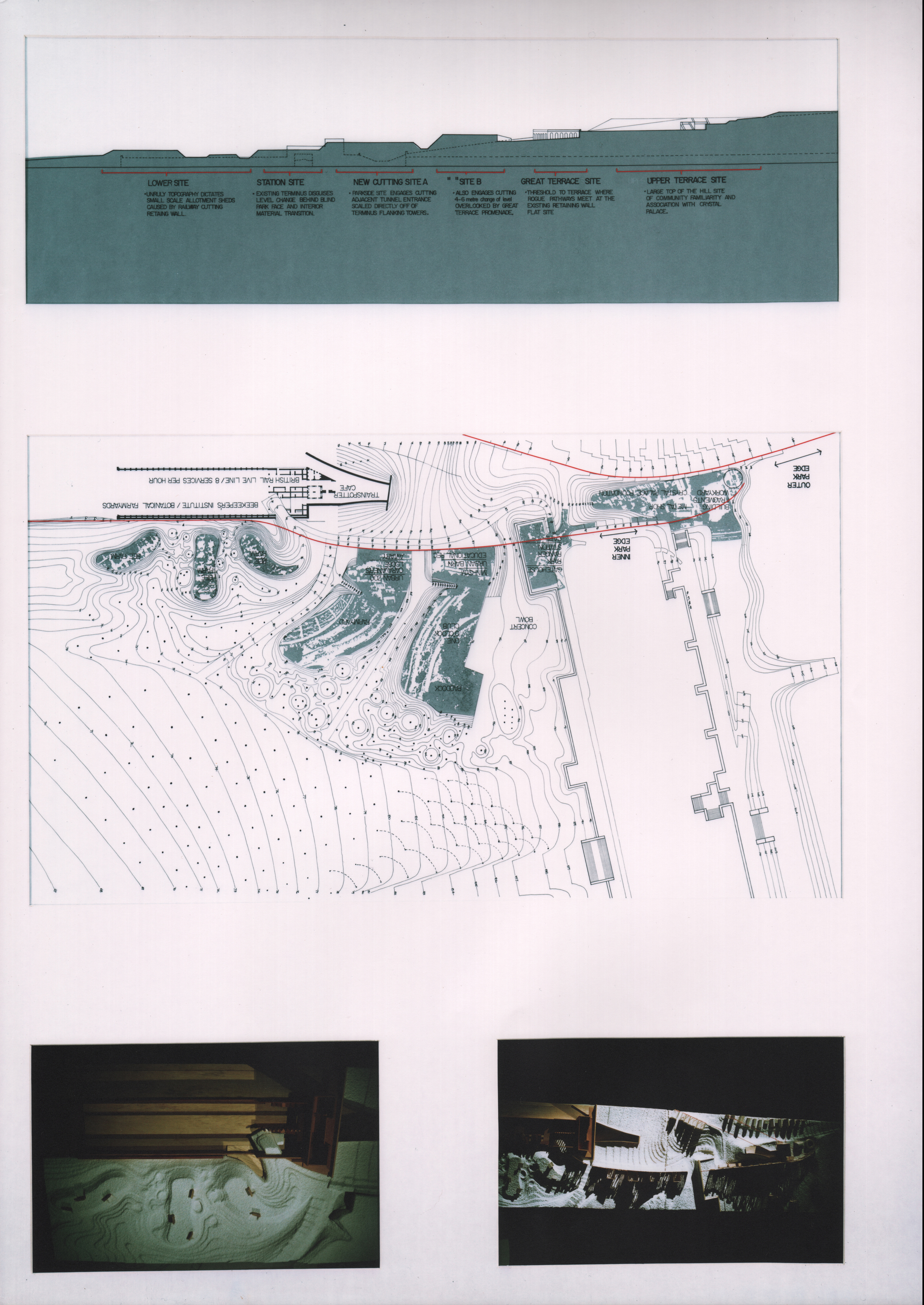
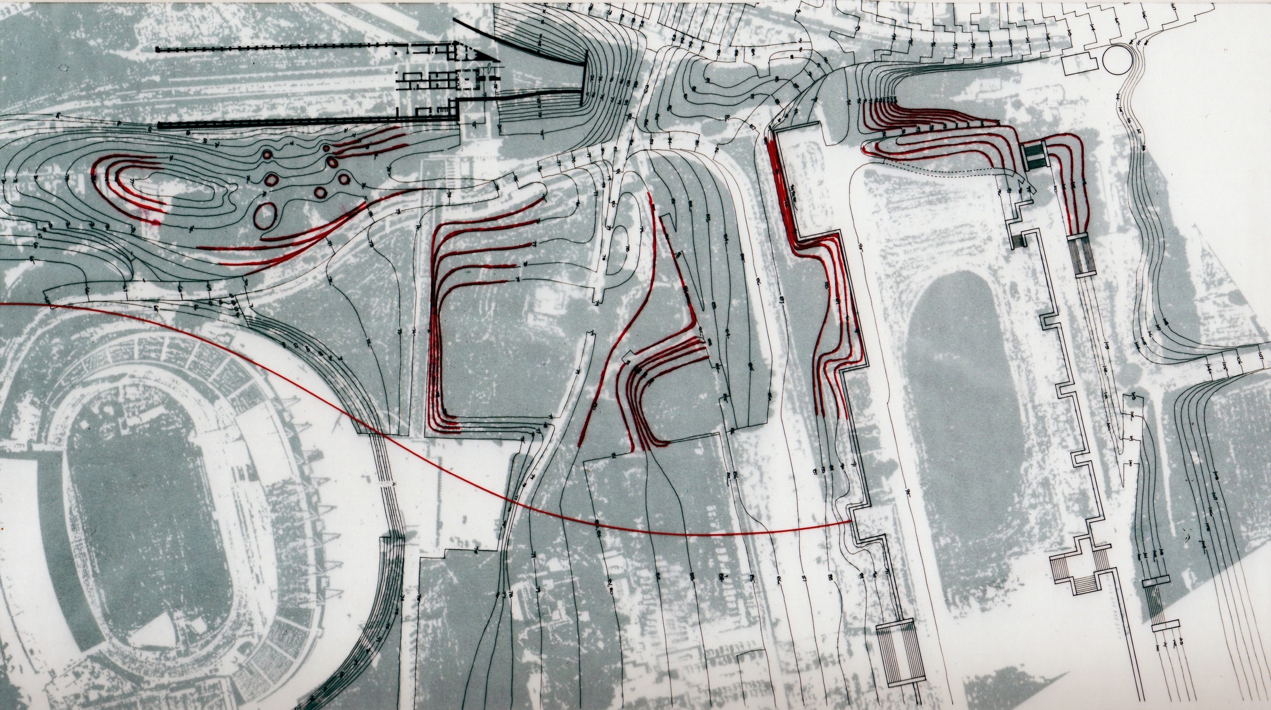
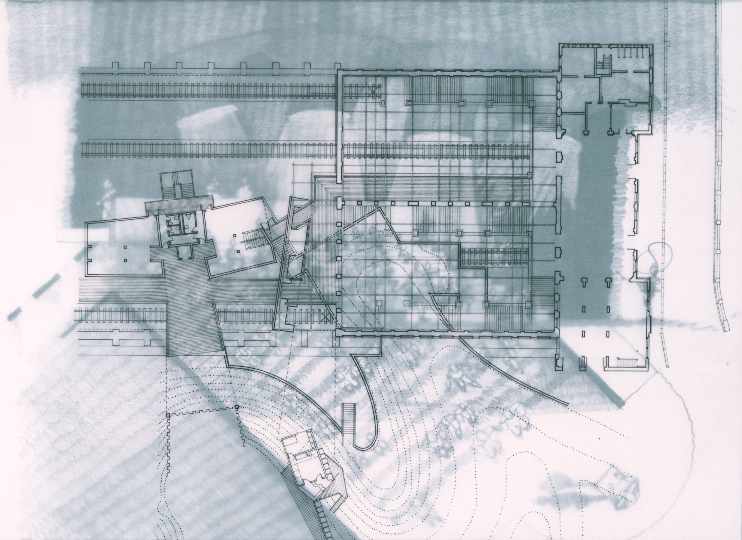
The red contour lines in the plan highlight the existing contours that are caused by "dumping" by previous deposition of debris and therefore define a precedent location for current "dumping" or deposition of debris from the current proposal to demolish the 22 buildings scheduled to be buried above. By comparing the existing and proposed contour plans (based on 25,200 cubic yards of demolition debris) one can see the evolution of the proposed landforms compared to the current grade.
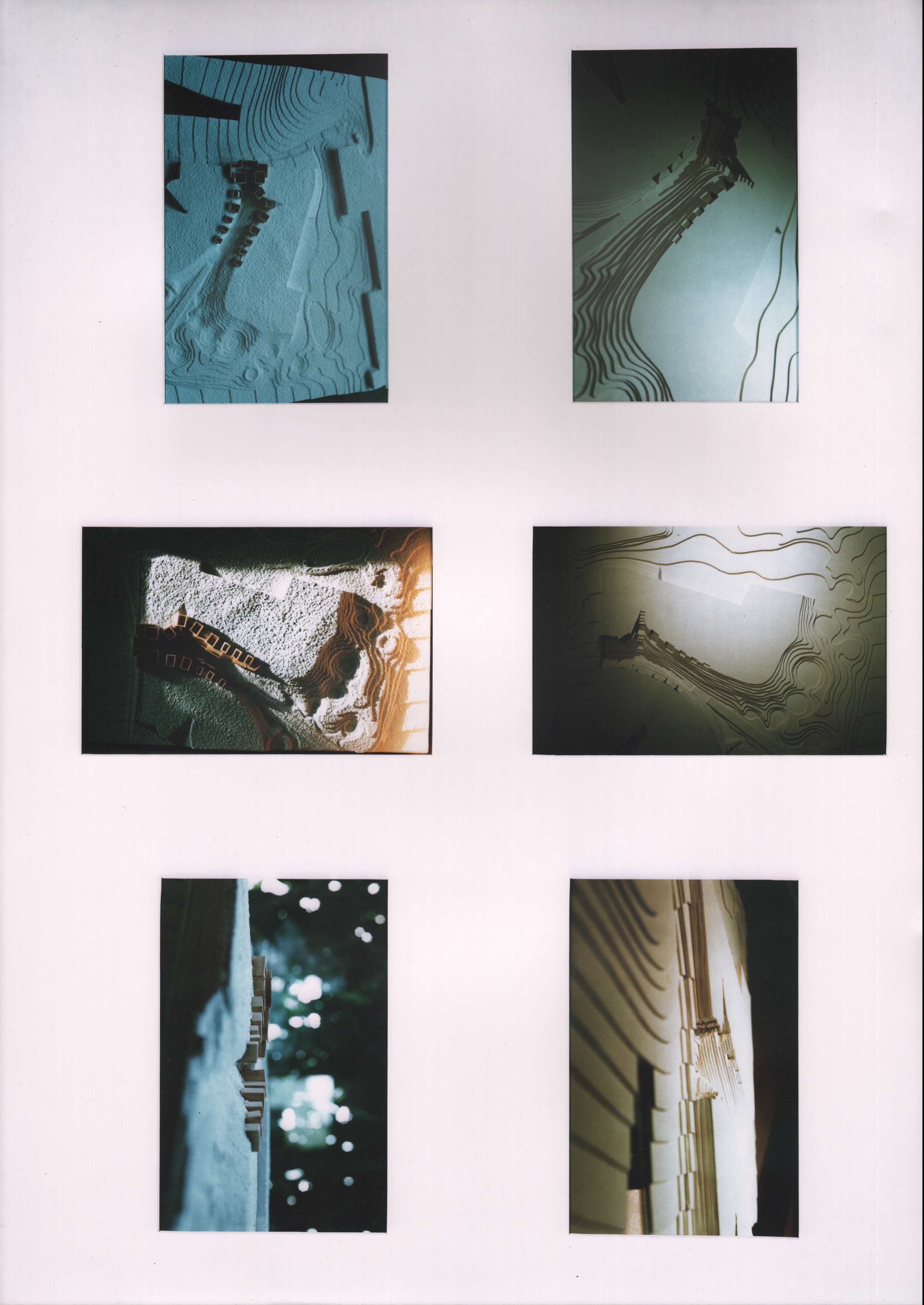
The addition of more landfill to these existing mounds from the Victorian Era is an exercise that has attracted a great deal of attention to the proposed grading plan by constructing 1:500 scale topographical models, These models, themselves the result of contour sketch investigations, are then transposed into larger scale topographical models as will be shown below. The objective of these studies is to evolve the proposed site plan as carefully as the development of the geometry of the building that will be accommodated using the rules described above.
The plateaus (shown in the site section to the right) step down with the slope of the park and rise to a height above the existing grade that will provide views across the park landscape. From atop these plateaus, it will also be possible to comprehend activities on the downhill plateaus. The activities that occur on each of these will not, as discussed above, involve the construction of any permanent structures.
In plan, these plateau shapes are the result of careful building up of the contours from lower levels that have public footpaths predetermining the shape of the base. Therefore, the plan shapes are further registration of movement systems between the park and the community that survive the very same debris that once formed buildings in the park that these paths delivered visitors to.
The Low Level Station also has retained a very large amount of earth moving that was the result of the original 1860s railway cut. Additional debris deposition can be observed in this area immediately adjoining the train shed wall shown in the photo above. The proposal shows additional plateaus adjacent to this wall that have received some of the additional demolition landfill of the 22 building schedule above. These plateaus provide the opportunity for foot travel from inside the rail station, over the 150 year old brick retaining wall and into the park using the plateaus as a stepping stone. These transitions are not the subject of this project.
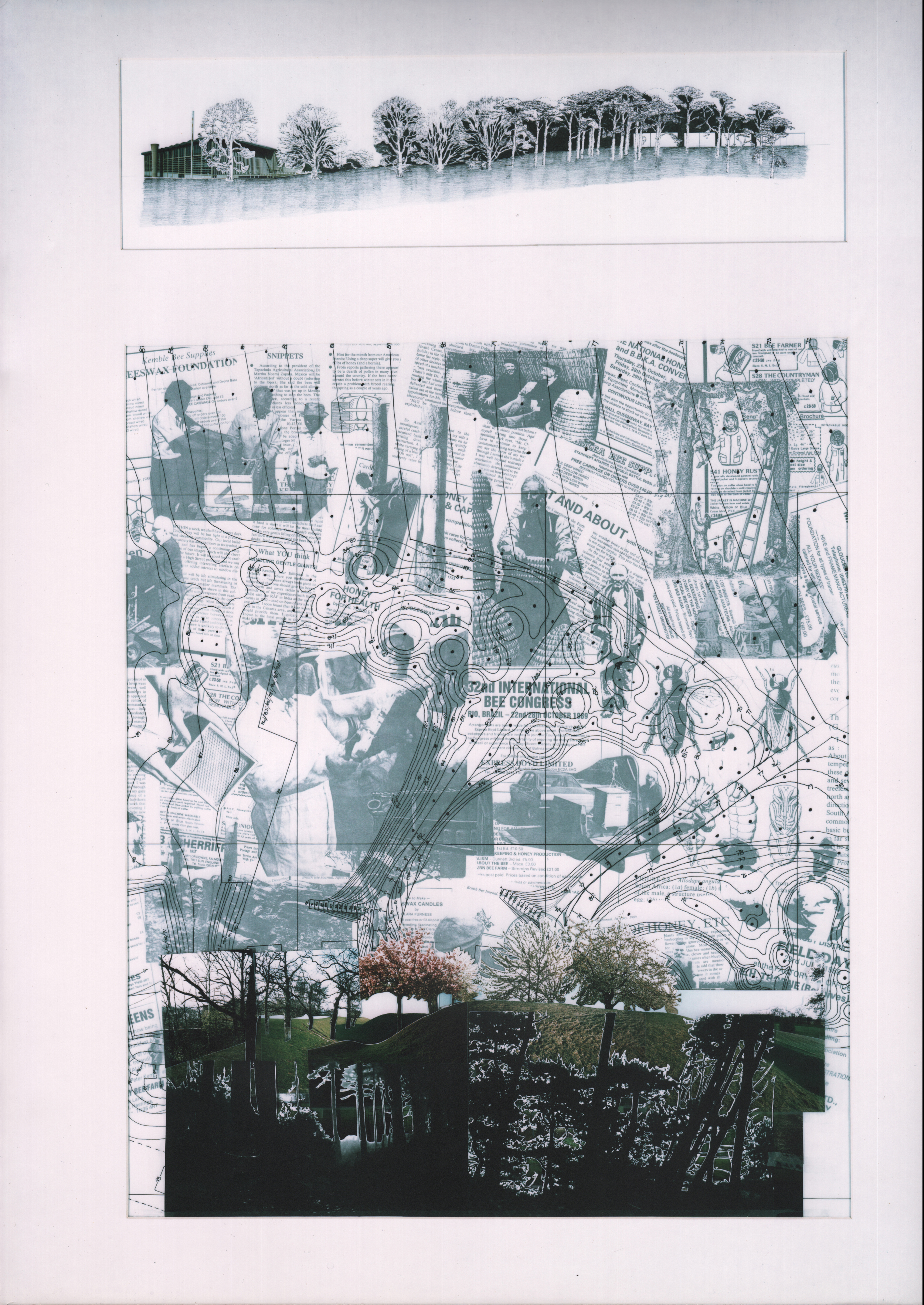
The existing deciduous trees are visible in the soil unaffected by the landfill activities. The Marine Pines become prevalent in the affected soil. This soil also happens to be the most unruly topography (steep and crater laden), The sketch (right) is illustrative of the intent to landscape the edges of the plateaus with Marine Pines which have the benefit of providing views through their tree trunks, through to the tops of the plateaus and the activities that take place there. This curious place at the top of the plateau in the coniferous trees is the desired affect that this place should have upon foot travelers that pass by on public footpaths.
The Sports Centre (the only building in the park that is preserved from demolition) is visible in the left side of the drawing, on the downhill slope. This region of the park is exclusively landscaped with indigenous deciduous trees and the Sports Centre, which is obscured by the Deciduous Trees at the base, is easily visible above the trees, largely due to the enormous scale of the Sports Centre. Hence the converse landscape goals of plantings around the park and plantings around the institutional buildings are opposed to each other and differentiate their respective territories.
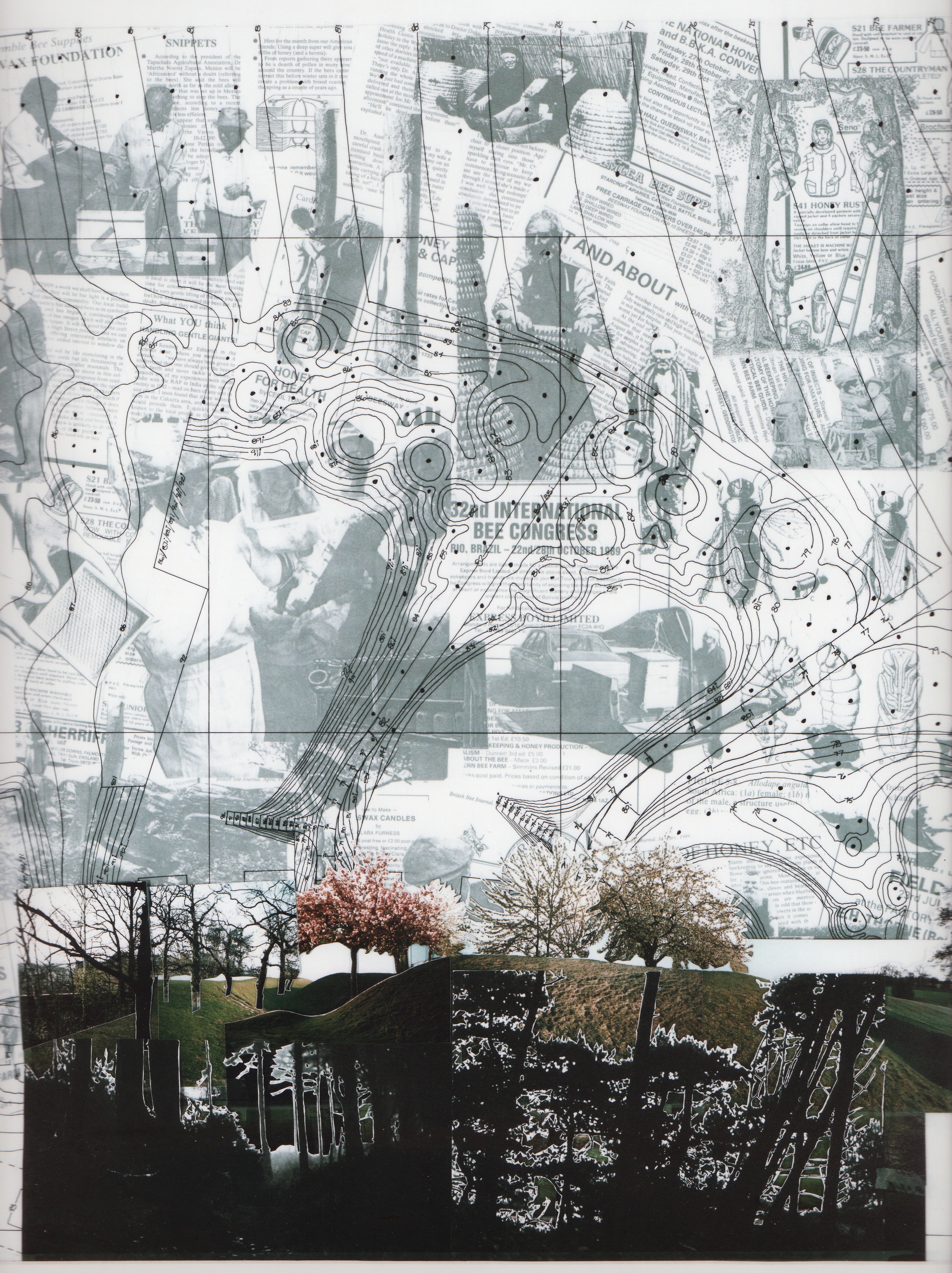
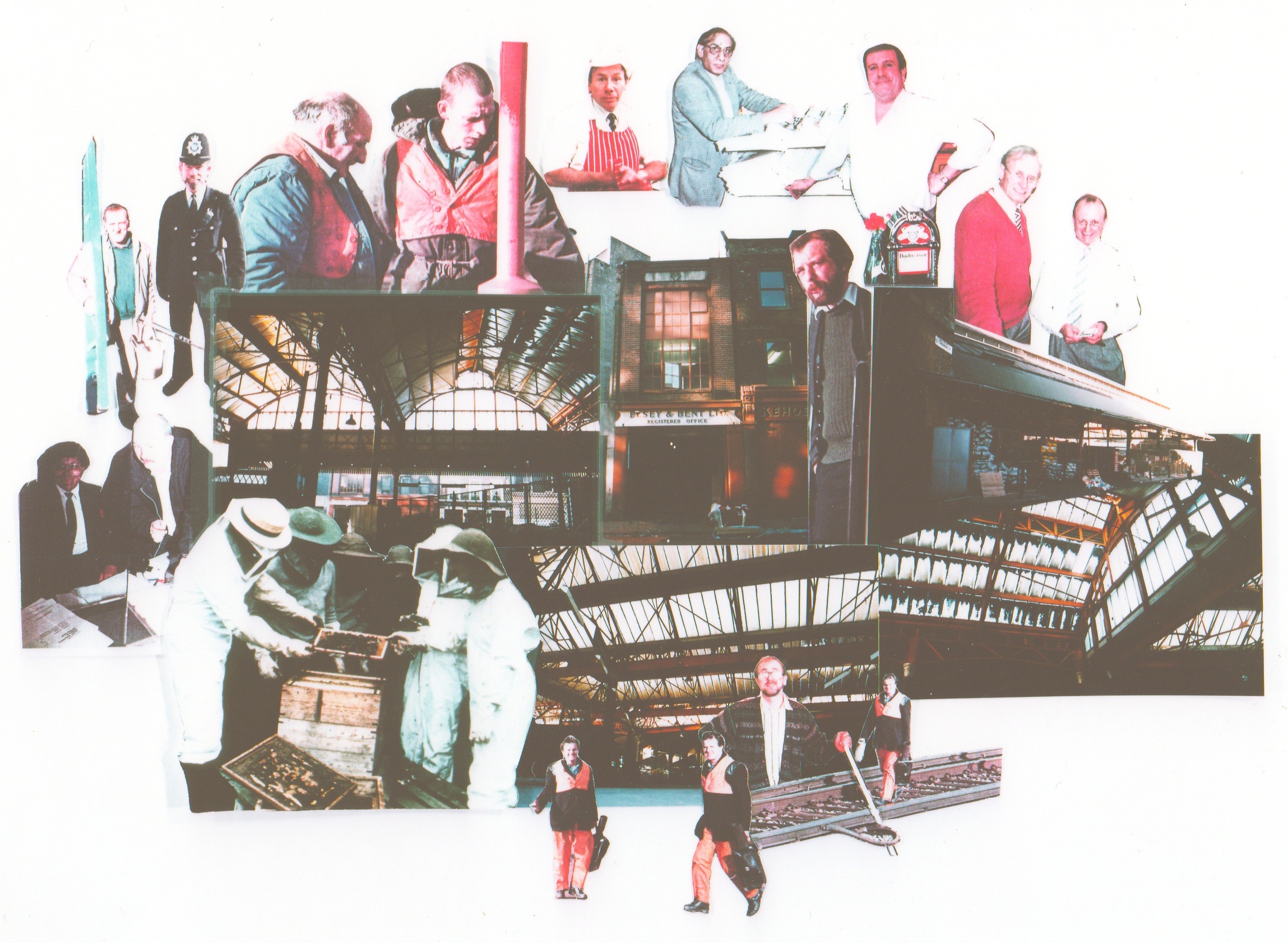
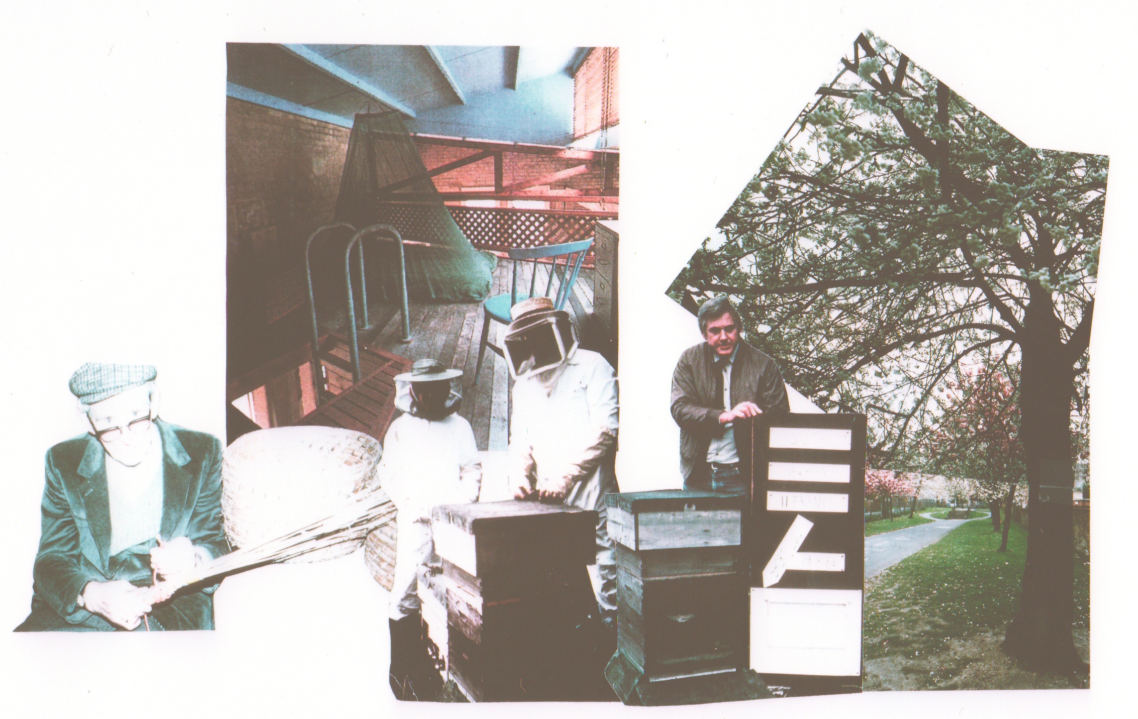
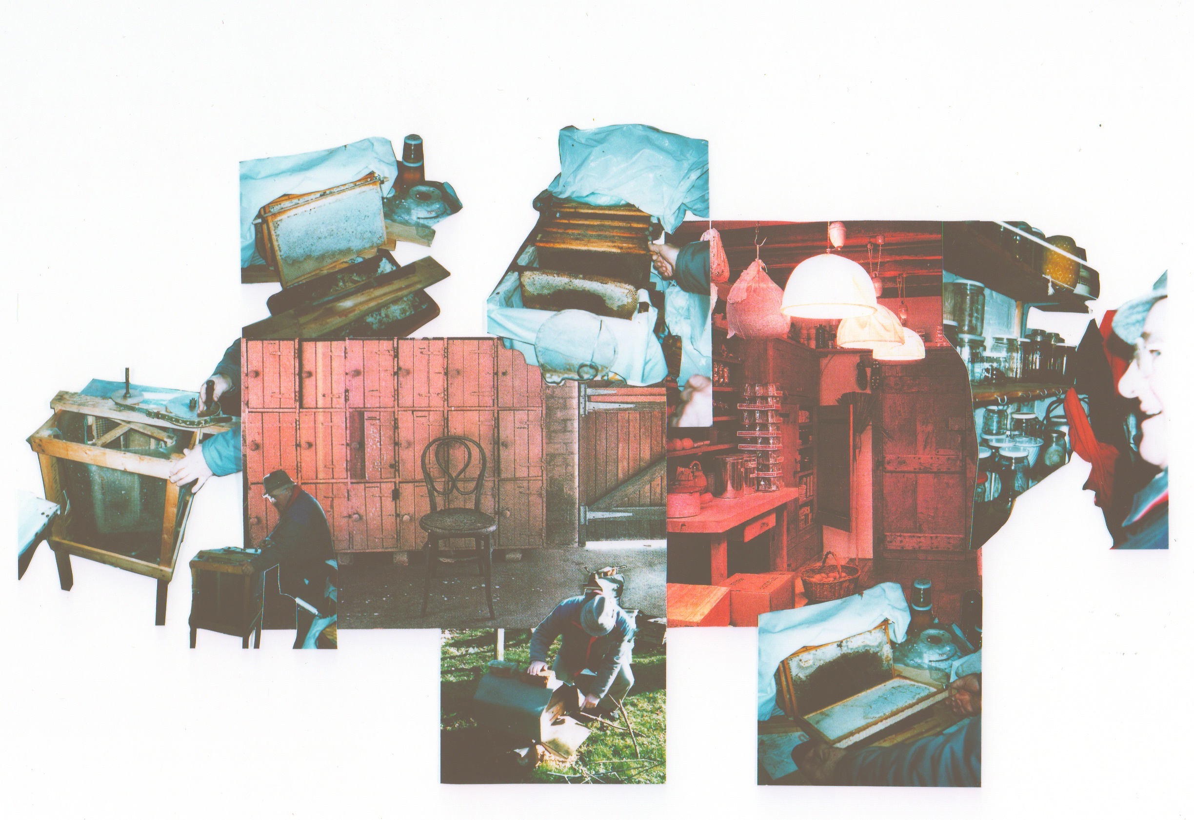
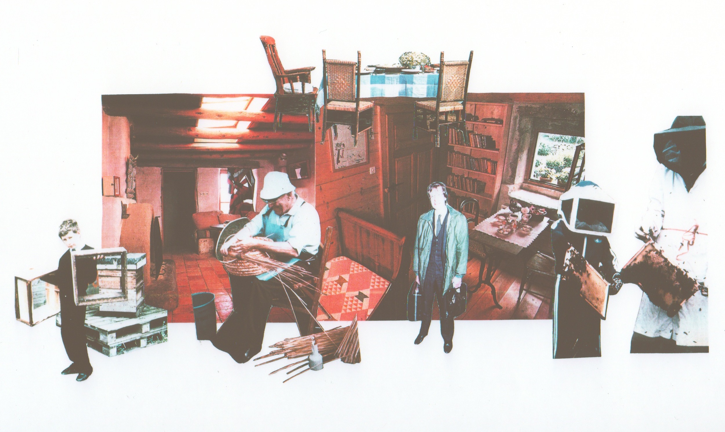
The collage (right) superimposes the activity of Beekeeping onto the planting layout and contour plan with jumbled cutout photos of Marine Pines and Cherry Trees (special activity-related plantings for the Bees pollination and nectar forage). This hodge-podge of seemingly unrelated items come together in this collage to communicate a cross-fertilization between the bees, the landscape and the topography.
Once the land masses had taken form, the plateaus defined and the movement systems, thresholds and boundary with the community were established, the building rules simply had to be followed and the enjoyable process of populating the edges of the plateaus with retaining construction- and the spaces that would be formed by them had begun. The program for the Beekeepers Institute contained approximately 15 different major spaces of varying size and public/ semi public/ private nature to each space.
Briefly, the program is descriptive of a working institution that manufactures, educates, archives genetic material, imagery, literature etc. and provides hermitages for individual bee masters to occupy during the flying season. There is also a retail component to the Institution that attracts members of the public to purchase bee products, books, apiary supplies and clothing. There are woodworking shops that manufacture the wooden parts to the various bee hives and other components of beekeeping practice.
The spaces range in size from the largest- a lecture/ exhibition hall which seats over 1000 people and contains 300square meters of exhibition space with a restaurant, kitchen, sanitary facilities and internet cafe...to the smallest- a bee master's studio that is only 20 square meters, contains a table and chair, a small food preparation area and a sleeping area. All of the volumes that make up the entire program consist of the following;
1. Exhibition Hall
2. Lecture Hall
3. Members Room
4. Restaurant, Kitchen, Dining, Toilets
5. Internet Cafe
6. Retail Shop
7. Wood Products Manufacturing Area
8. Hermetically Sealled Honey Extraction, Ripening and Bottling Factory
9. Hive Assembly Area & Inventory Storage
10. Library and Slide Library
11. Locker Room w/ Showers (M&F)
12. Bee Masters Hermitages
13. Live Bee Class "Rooms"
14. Tool Shop
15. Emergency Response/ First Aid
Close-up of Existing Grade/ Park Threshold/ Movement In & Out;
(Re-Iteration)
"In exploring the southern boundary of the park, there falls upon the landscape a limit beyond which the streetscape of the community, with it's pavement, roads, curbstones, buildings and signposts give way to the softer textures of the park with it's gravel walkways, grasses, undulating ground and retaining structures. This limit is also informed by the grand space created by the Crystal Palace Low Level Station West Facade. There is also a gaping crater in front of the Low Level Station which is the entrance to the Sydenham Hill Rail Tunnel. By determining a hard edge to the park, the deposition of debris resulting from demolition of the 22 buildings scheduled for destruction can be dumped up against a retaining wall of core-ten steel sheet pile that contains the debris effectively drawing strength from it and rises above it and becomes perforated by selective oxyacetylene cutting to reveal an evocative motif of marine pines that come to life just beyond."
Close-up of Landscape Strategy;
(Re-Iteration)
"These curious conditions are telling of a possible landscape strategy that could determine tree placement. Since all of the existing trees are deciduous, and grow out of a loamy indigenous soil, they reflect those soil conditions and shall be preserved in a similar manner as the Victorians who moved debris around the park by horse cart and relented from burying tree trunks in backfill. Hence the craters that are visible around Poplar and Tulip Trees that are common to the southern edge of the park. New tree plantings that will be asked to grow in landfill conditions (sandy loam with hardcore and other debris) will reflect those soil conditions and the location of these trees will be determined by a simple fractal that responds to the steepness (more frequent plantings) or the shallowness (less frequent plantings) of the grade in any particular part of the site where topographical change is being driven by deposition of demolition material. After the fire of 1936 that incinerated the Crystal Palace Building, there was hundreds of thousands of tons of broken glass, melted iron, and other non-biodegradable debris that required disposal and burial. The park grounds offered a ready-made dumping ground for this material."
Close-up of Grading Strategy-
(Re-Iteration)
"The plateaus (shown in the site section to the right) step down with the slope of the park and rise to a height above the existing grade that will provide views across the park landscape. From atop these plateaus, it will also be possible to comprehend activities on the downhill plateaus. The activities that occur on each of these will not, as discussed above, involve the construction of any permanent structures. In plan, these plateau shapes are the result of careful building up of the contours from lower levels that have public footpaths predetermining the shape of the base. Therefore, the plan shapes are further registration of movement systems between the park and the community that survive the very same debris that once formed buildings in the park that these paths delivered visitors to."
Close-up of Massing Strategy-
(Re-Iteration)
"Once the land masses had taken form, the plateaus defined and the movement systems, thresholds and boundary with the community were established, the building rules simply had to be followed and the enjoyable process of populating the edges of the plateaus with retaining construction- and the spaces that would be formed by them had begun. The program for the Beekeepers Institute contained approximately 15 different major spaces of varying size and public/ semi public/ private nature to each space."
The Public Spaces are located at the southern-most end of the Institute at the edge with the community and the most private spaces are located at the northern-most end of the institute (in the park). This gradual transition from public to private occurs over the entire length of the institute which is a series of indoor, indoor/outdoor, outdoor, and indoor spaces that present themselves along a linear path that starts at the top of the uphill plateau and descends downwards to the toe of the slope (into the park) at the end of the down hill plateau.
Close-up of Planting Strategy- (Re-Iteration)
"The existing deciduous trees are visible in the soil unaffected by the landfill activities. The Marine Pines become prevalent in the affected soil. This soil also happens to be the most unruly topography (steep and crater laden), The sketch (right) is illustrative of the intent to landscape the edges of the plateaus with Marine Pines which have the benefit of providing views through their tree trunks, through to the tops of the plateaus and the activities that take place there. This curious place at the top of the plateau in the coniferous trees is the desired affect that this place should have upon foot travelers that pass by on public footpaths."
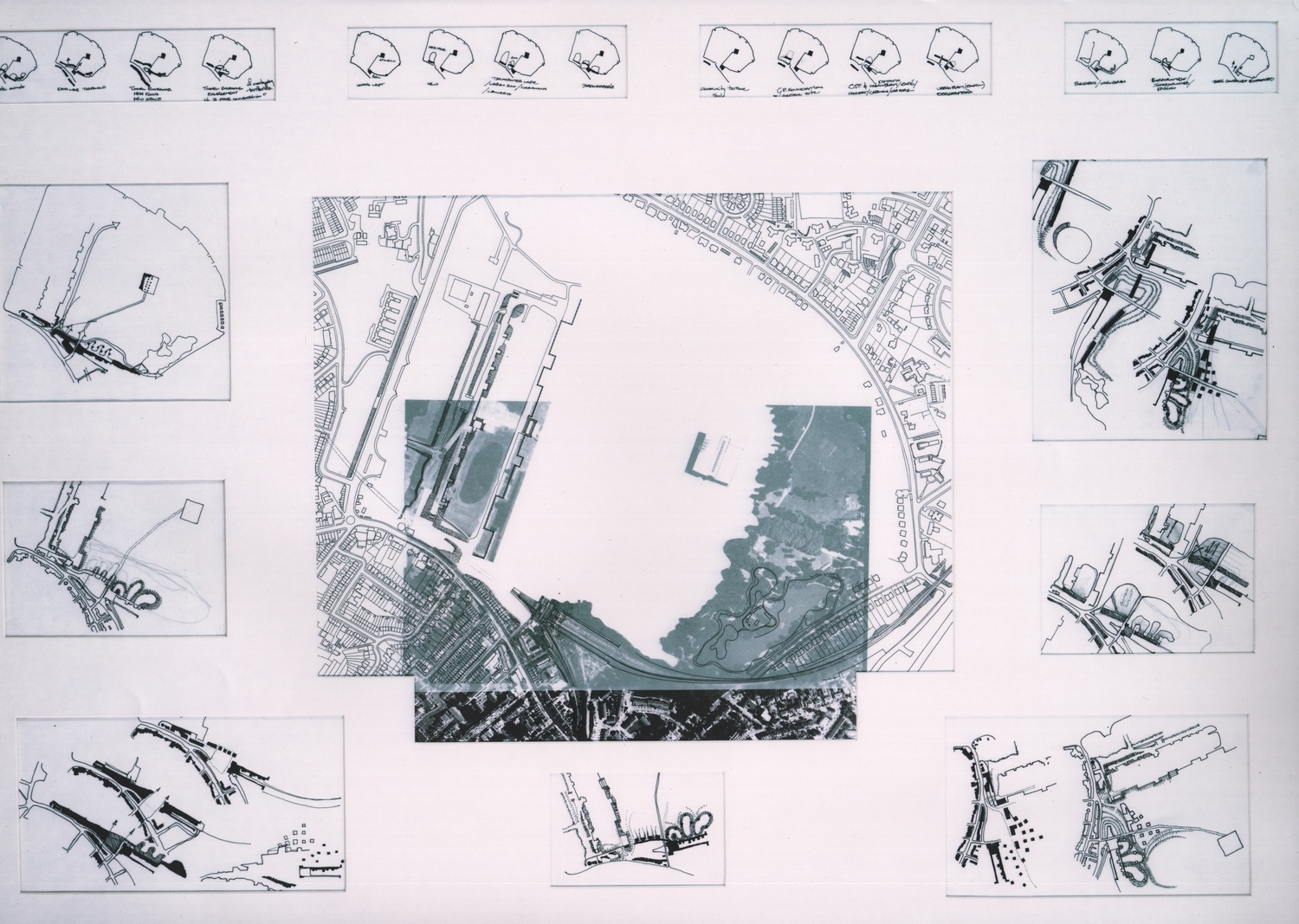
Series of Sketches exploring the placement of building mass along the community edge;
As can be shown in the sketches to the right, the community edge (the long east west wall that retains the landfill) is engaged by separate building masses along it's length. This approach was aborted after several other sketch studies included the landfill masses (the plateaus) and used the chasm between these plateaus as a linear progression instead of the retaining wall.
Progress Sketch:
Once the sketch began to break up the massing along the edges of the plateau and deployed them for the purpose of slope stabilization, the strategy of rules began to take form and the design unfolded after a series of additional sketches.
Progress Sketch:
The buildings and the topography remained separate studies in early sketches, divorcing the two design elements so that it was difficult to synthesize a coherent strategic diagram. This sketch is one example. By using the satellite photos and topographical plans together with the massing sketches, it was clear what was required to move forward.
Progress Sketch:
This "destination building" is filtered by the access through the Beekeeper's Institute public walkway. What this sketch begins to uncover is the path into the park can be populated by institutional buildings as a threshold. As will be shown below, accurately scaled topographical information would tune up the diagram and lead toward a schematic plan.
The sketch to the right is of a concept that eventually evolved into the final concept. The buildings would follow a progressively public to private series of structures and spaces that one would encounter on the way into the newly landscaped park. These buildings would provide a marketplace of information about bees, their care and living conditions, and their surviv
Progress Sketch:
Prior to informing the building concept plan with the more accurate contours and scale, this sketch radiates the more private buildings out into the park, away from the community edge while the larger more public buildings draw upon the strength and size of the retaining wall that is introduced to hold back the landfill along the same edge.
Progress Sketch:
This was the last of the quick and dirty 1:500 sketched that started the direction of the concept toward more resolved, larger scale models and sketches. As will be shown below, much of the subsequent decision making was developed using models as well as larger scale plans.
Progress Model:
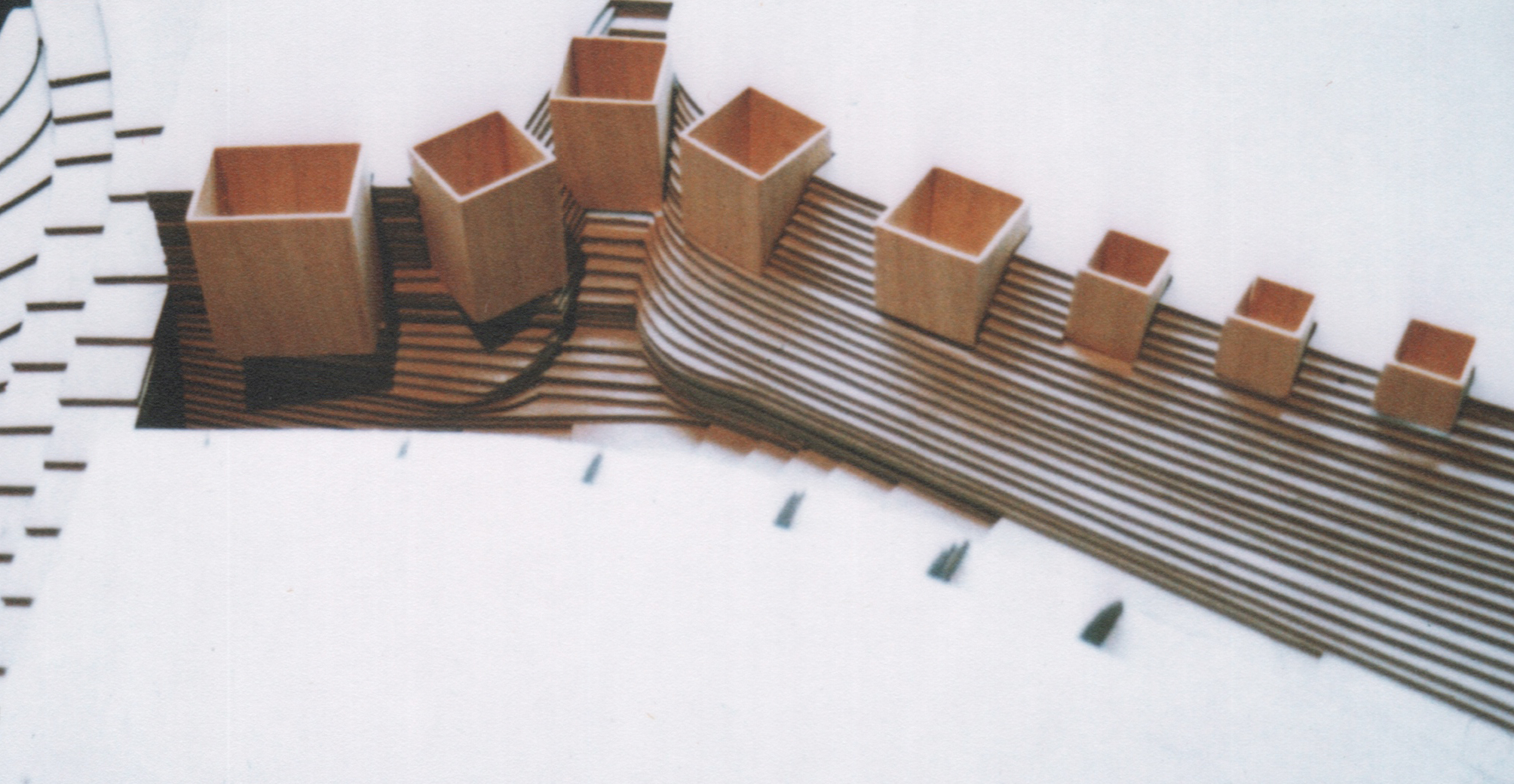
By using the construction to stabilize the slope and retain the landfill, these rectangular boxes also sit inside the landfill mound. This reduces the amount of mass that is presented in elevation to the plateau despite the fact that they are multistory buildings that have relationships with the public space on the top of the plateau as well as a relationship with the interior functions of the institute below.
Progress Sketch:
(Re-Iteration)
"The red contour lines in the plan highlight the existing contours that are caused by "dumping" by previous deposition of debris and therefore define a precedent location for current "dumping" or deposition of debris from the current proposal to demolish the 22 buildings scheduled to be buried above. By comparing the existing and proposed contour plans (based on 25,200 cubic yards of demolition debris) one can see the evolution of the proposed landforms compared to the current grade."
Progress Sketch:
(Re-Iteration)
"The addition of more landfill to these existing mounds from the Victorian Era is an exercise that has attracted a great deal of attention to the proposed grading plan by constructing 1:500 scale topographical models, These models, themselves the result of contour sketch investigations, are then transposed into larger scale topographical models as will be shown below. The objective of these studies is to evolve the proposed site plan as carefully as the development of the geometry of the building that will be accommodated using the rules described above.
Progress Sketch:
(Re-Iteration)
"The plateaus (shown in the site section to the right) step down with the slope of the park and rise to a height above the existing grade that will provide views across the park landscape. From atop these plateaus, it will also be possible to comprehend activities on the downhill plateaus. The activities that occur on each of these will not, as discussed above, involve the construction of any permanent structures."
"In plan, these plateau shapes are the result of careful building up of the contours from lower levels that have public footpaths predetermining the shape of the base. Therefore, the plan shapes are further registration of movement systems between the park and the community that survive the very same debris that once formed buildings in the park that these paths delivered visitors to."
Preliminary Topographical Model:
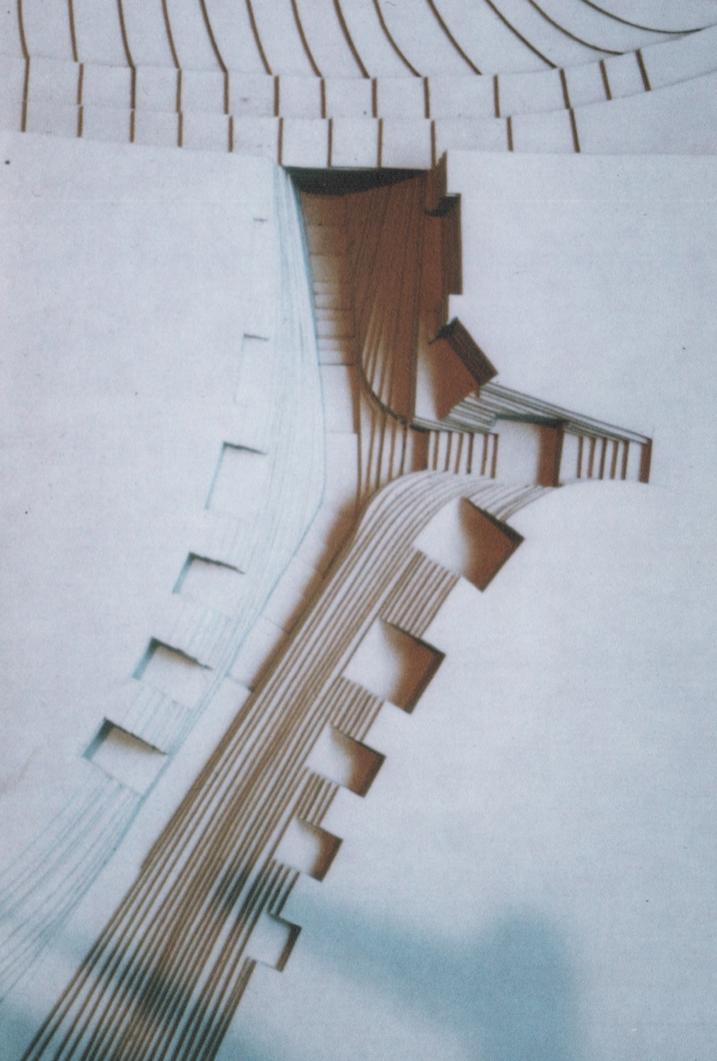
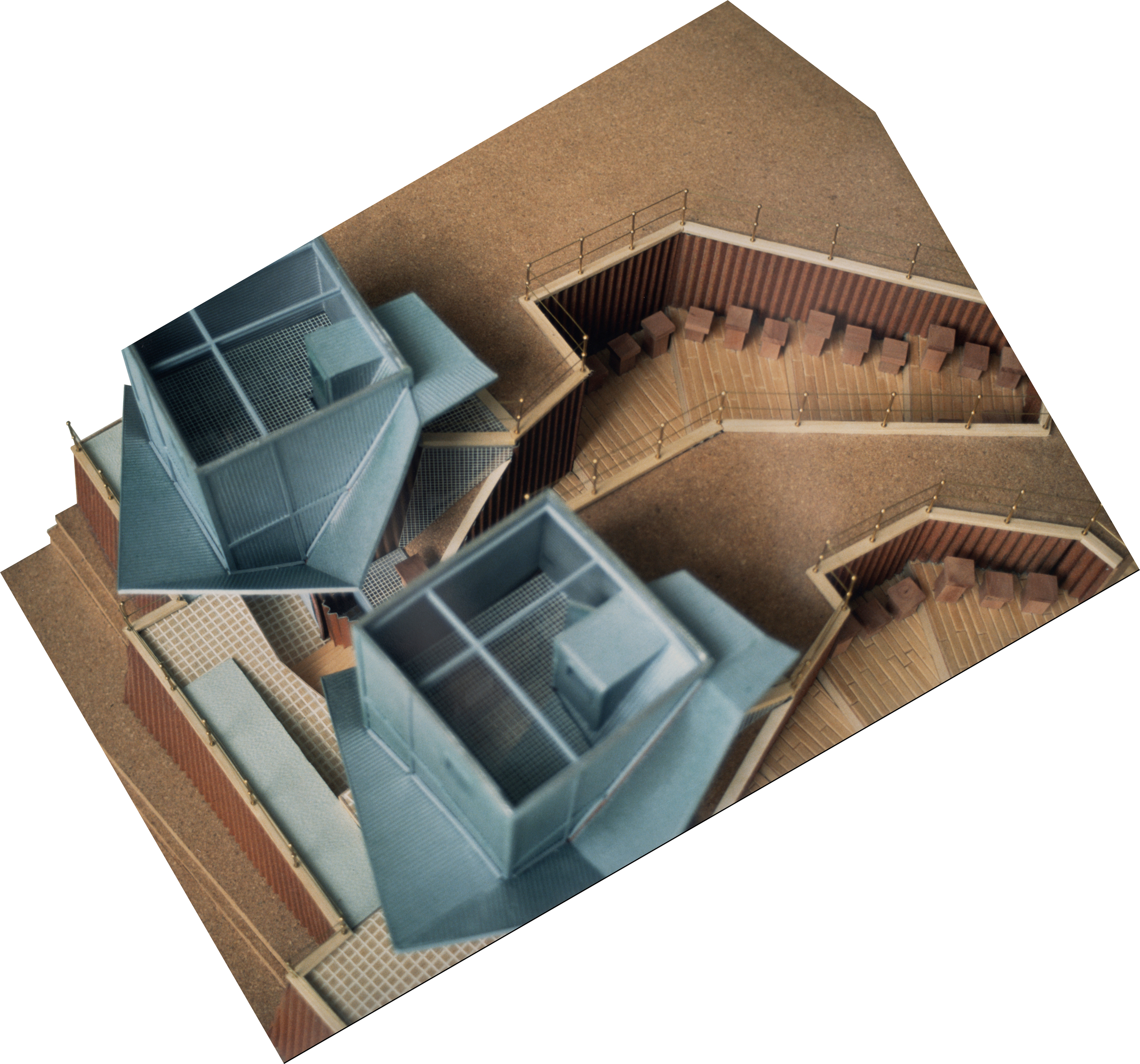
The settlement of little beekeepers' buildings into the chasm that separates the uphill plateau from the downhill plateau is the opportunity that best demonstrates the previously stated rules of design intent. By excavating retaining walls into the plateau, and incrementally stepping these foundation forms down into the landfill, these allow gaps between the little building forms for further opportunity to echo the same strategy but at a smaller scale. By introducing this gap between the buildings, a new cutting, into the plateau allows for access to the top of the plateau through a stepped farm yard where the beekeepers can stage their bee hives for positioning on the top of the plateau.
Study Model:
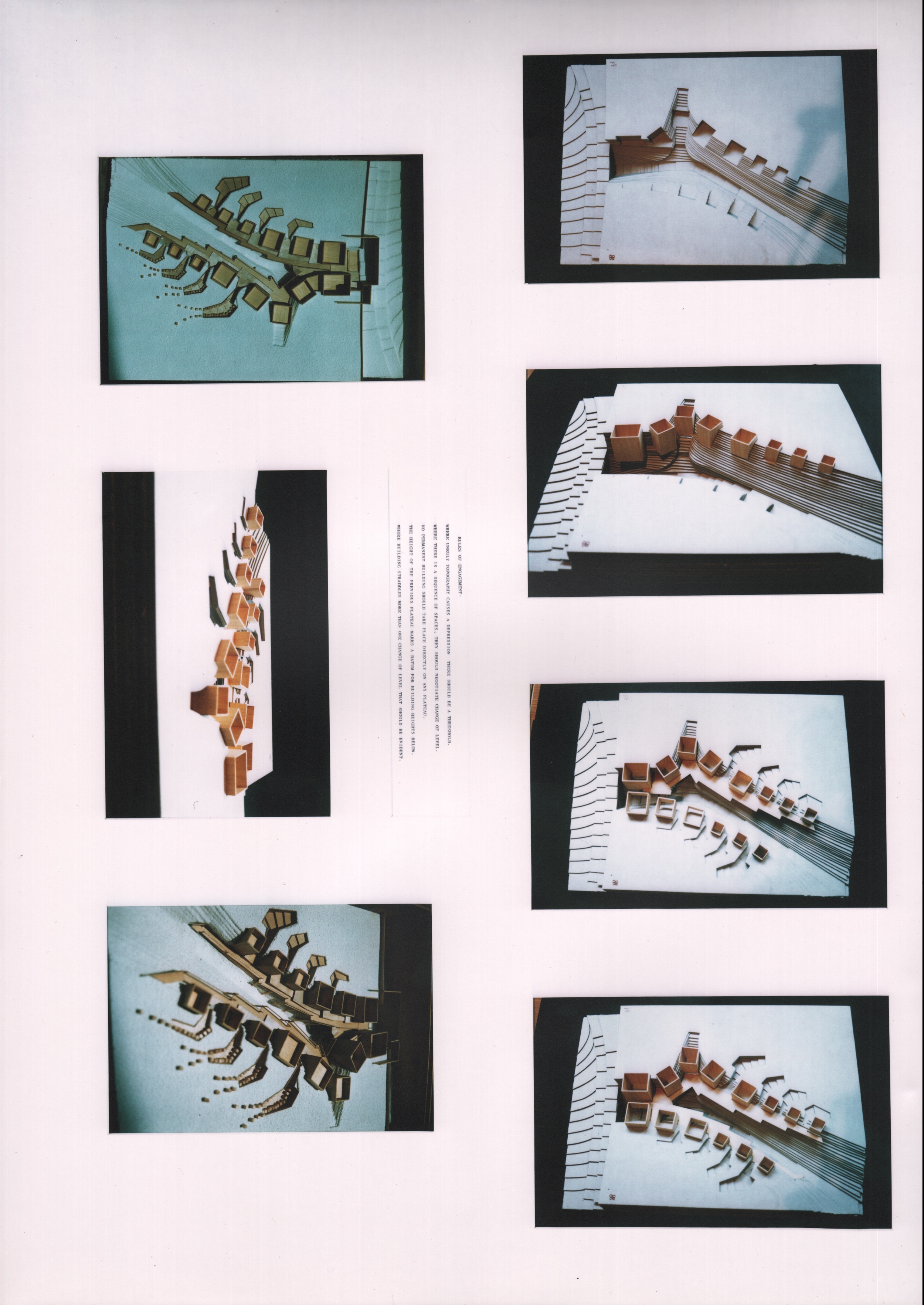
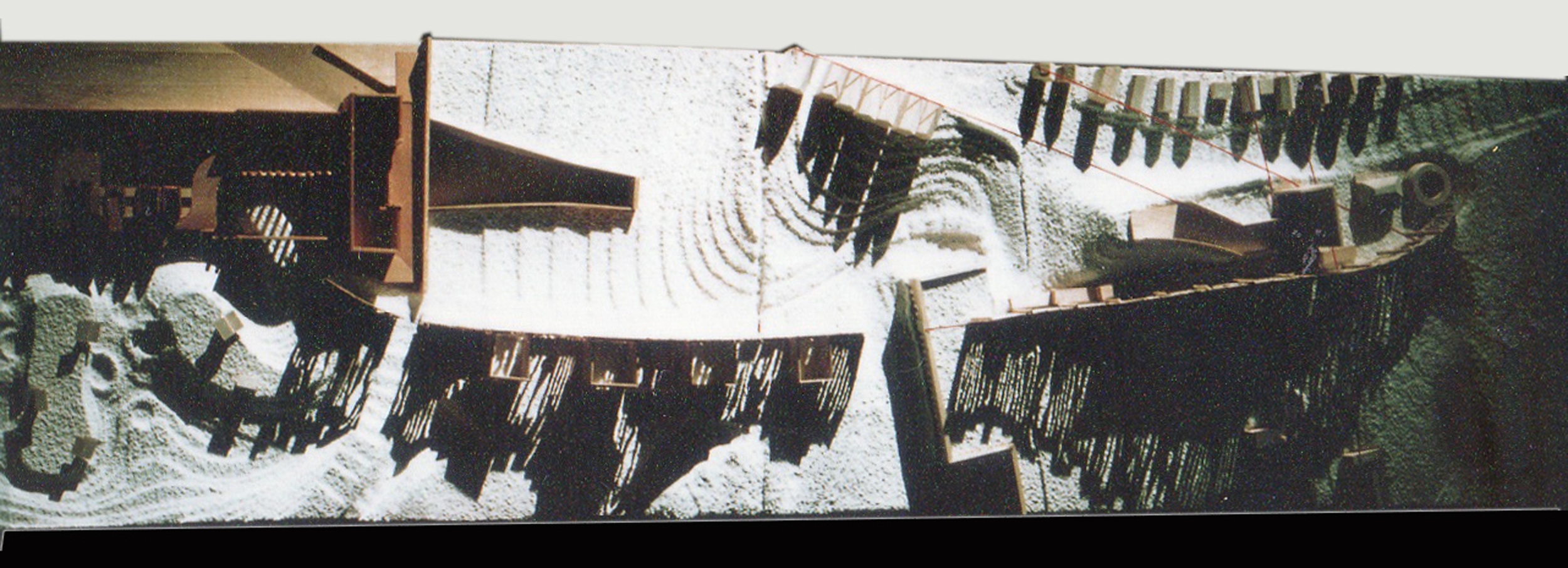
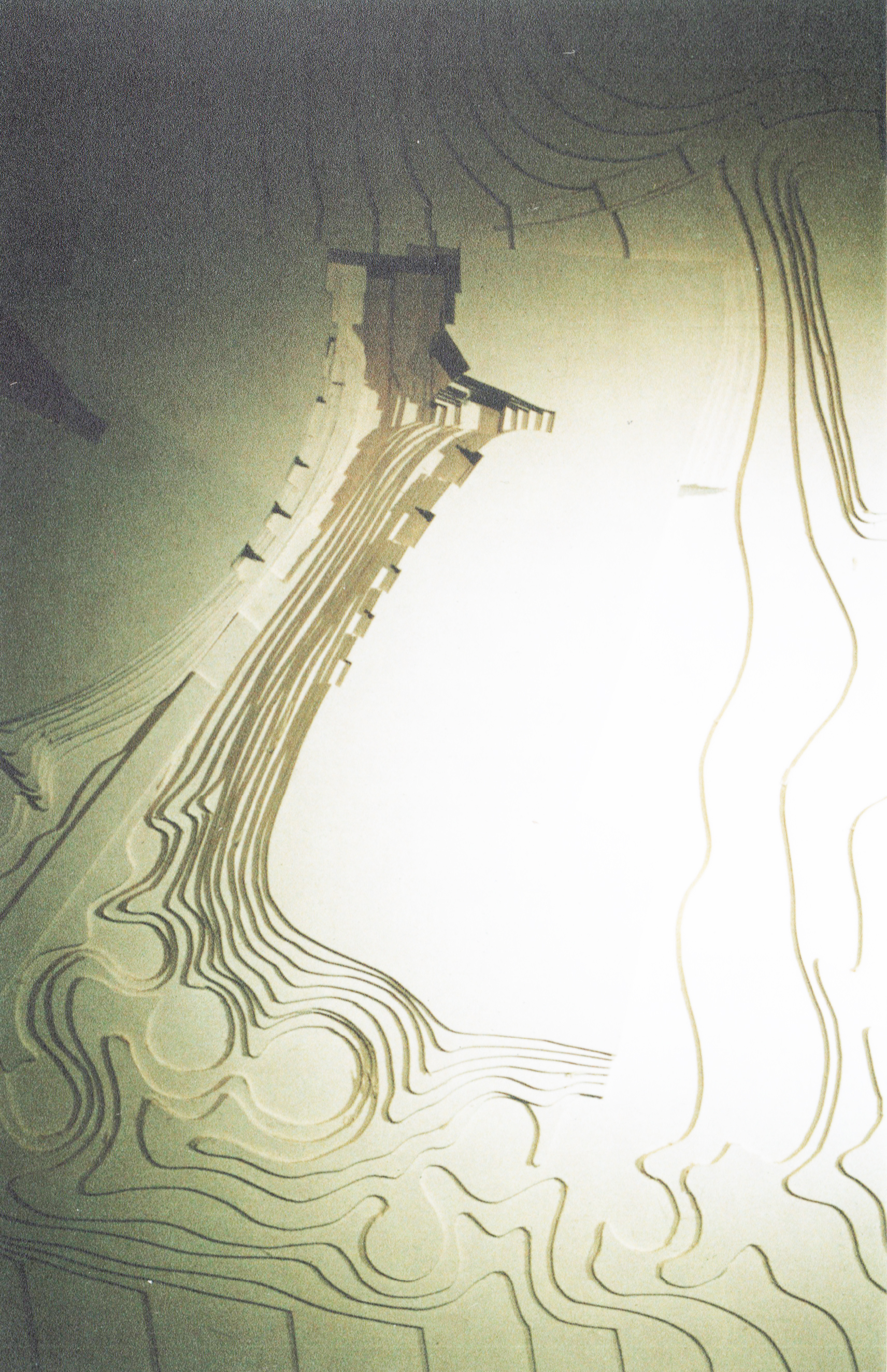
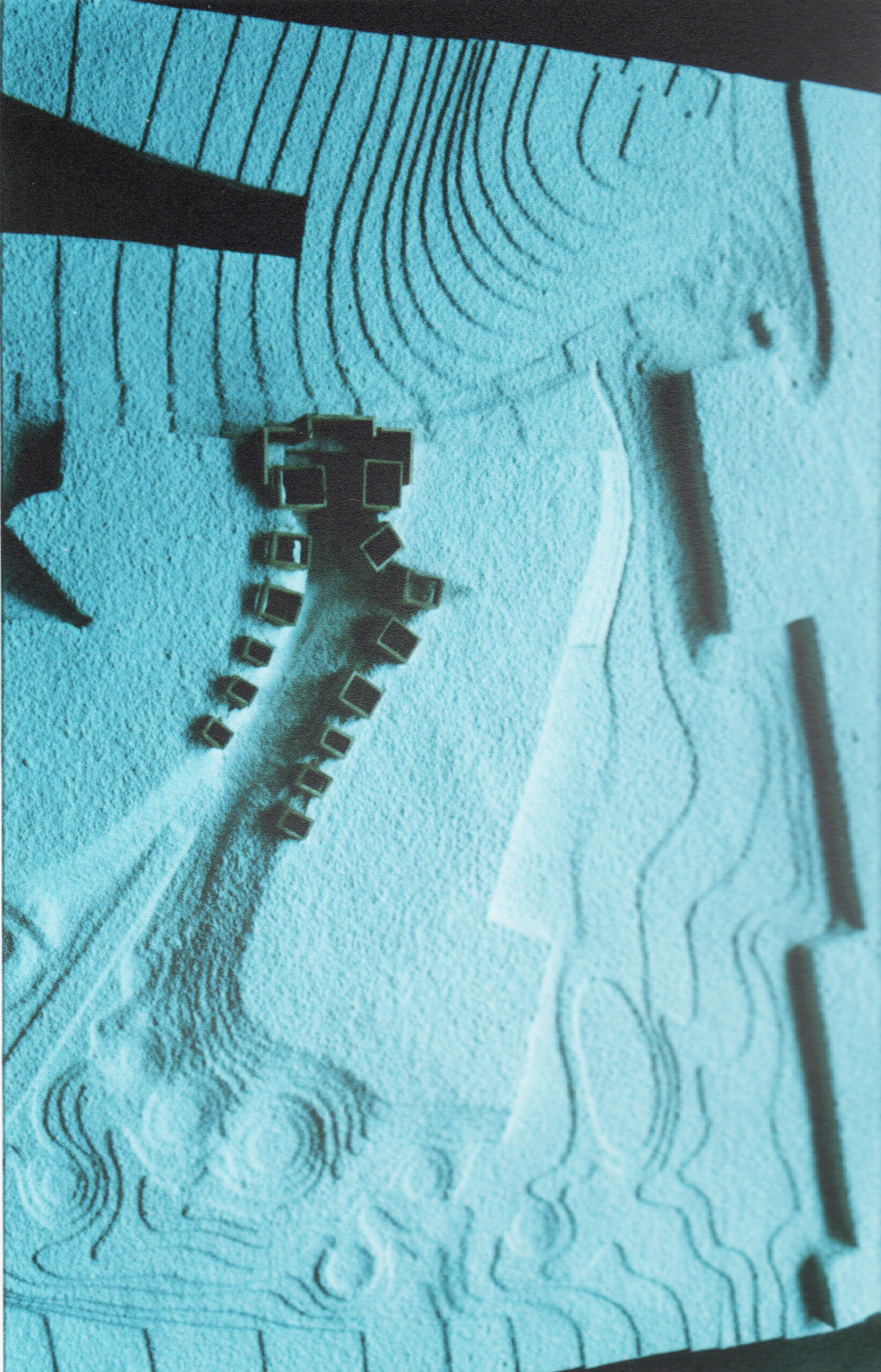
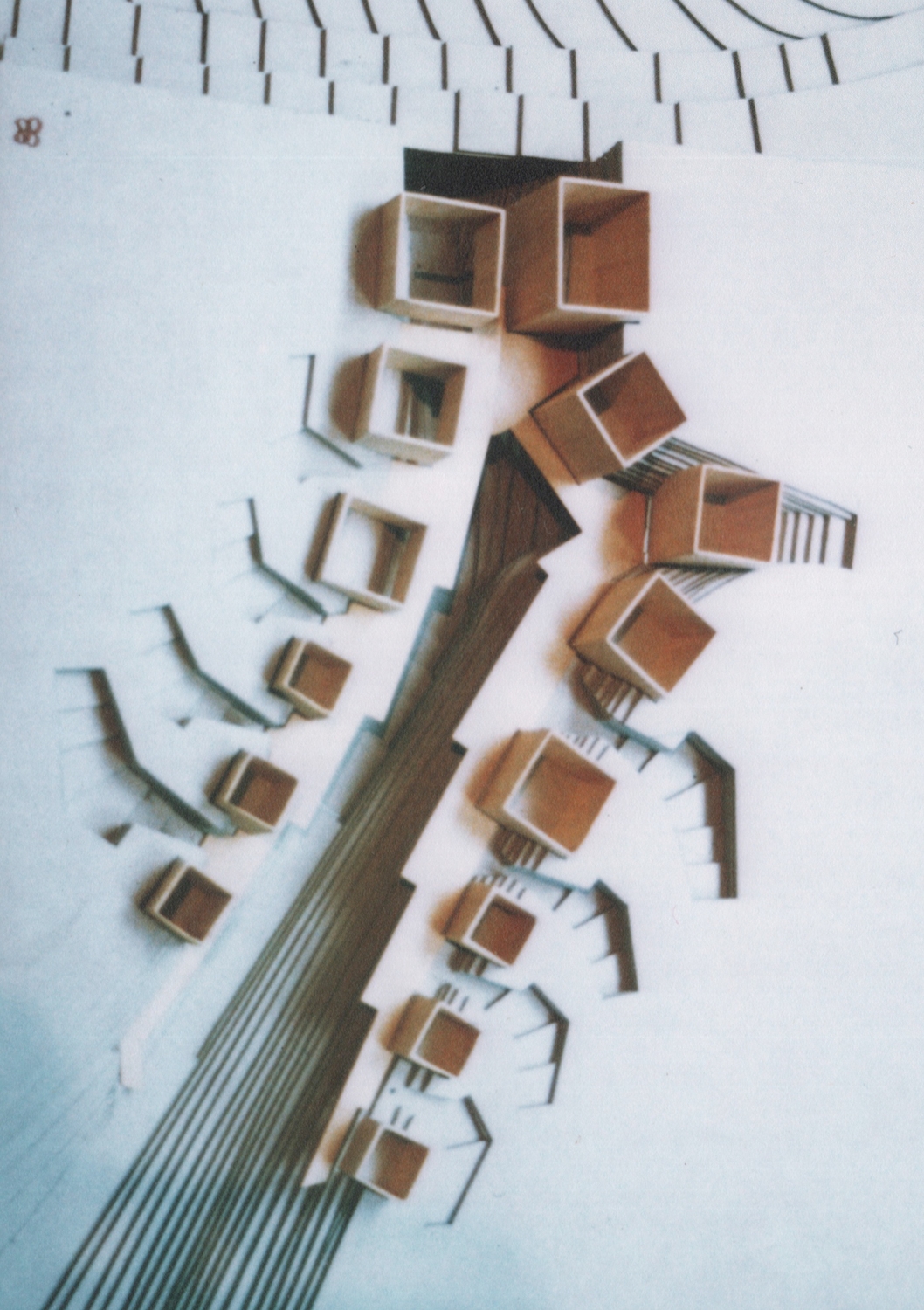
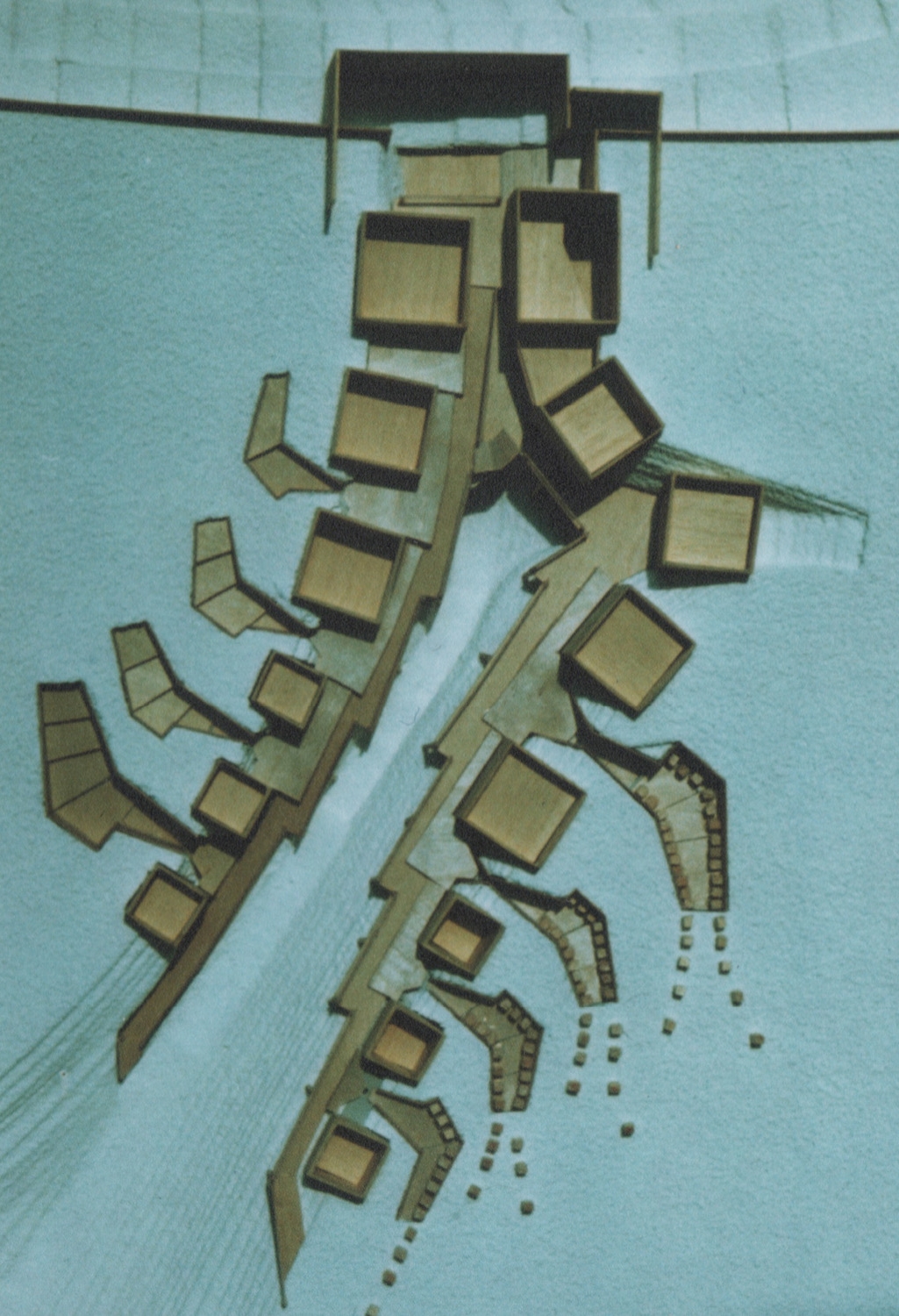
This 1:500 study model followed the sketches above. The extent of the landfill to create each plateau is estimated to be over 22,000 cubic yards (based the on the 22 building schedule of demolition). This model clearly shows the three thresholds into the park that are created by the topography. It also incorporates the community edge as discussed and the rudimentary building volumes are placed along the slope in a progression from public, larger spaces to private, smaller spaces.
Study Model:
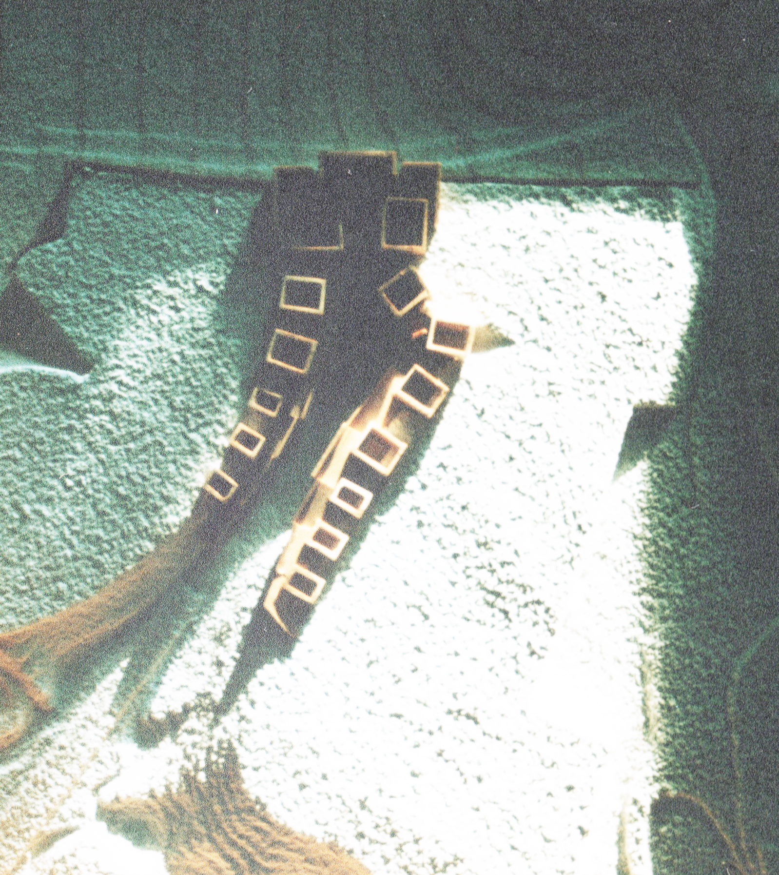
Close inspection of this model reveals the introduction of a series of ramps that connect the Bee buildings together on the chasm side of the buildings. This ramp will evolve to become a semi-public footpath that navigates the travel distance from the egress to the park, up to the lecture hall past several BeeMaster Cabins, past the manufacturing buildings and the exhibition hall at the crux of the institute, under the slide library and past the retail store, the bottling plant and past three Bee Masters Cabins and up onto the top of the uphill plateau.
The Chasm-
In the deepest, darkest depths of the topographical depression between the plateaus lies a sloping ramp that leads down into the historical rail tunnel and the Crystal Palace Low Level Rail Station Crypt where, as institutional programming would have it, a Trainspotter's Cafe would exist using space above the tracks that are disused on the north side of the station. This ramp will also provide access to the suburban rail platforms for BeeKeepers commuting into the Institute from Victoria or from Kent. Access to the uphill plateau from the bottom of the chasm directly to the uphill plateau is possible with a transition into and out of the retail shop that sells honey and other bee products and apparel. The plateau is at the top of the stairs and has hundreds of bee hives situated in clusters on the edges of the bee farm.
Farmyard Fractal-
With the introduction of the farm yards between the buildings, a much needed outdoor space for the beekeepers to work with bees, swarms, hive transfers and other activities (that result in congested airspace), the paradigm of using topography to create a threshold space is repeated on a smaller scale within the same project where the site strategy deploys the same concept but at a larger scale.
Model Mock-up-
Prior to building the final model, it was determined that the method of supporting the ramps using treated timber posts was going to be superceded by a new support system that created a retaining wall as the structure and the ramps themselves would sit ontop of landfill. The retaining walls would rise out of the chasm and support the ramps at an angle.
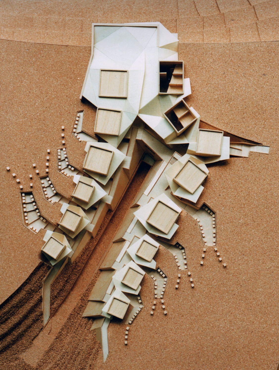
Final Site Model- but still evolves design
The change to the walkway ramps described above, specific changes to the roof structures, and discovery of spaces where articulation of the purpose was enhanced were all additional changes that were incorporated in the final model. As a planning exercise, the landscape, the topography and the building geometry were all significantly improved over the mock-up models. The ability to visualize the building and the spaces was invaluable in fostering the process of planning larger scale planning issues with interactive alterations that delivered a rigorous, yet intuitive project.
Final Model of Bee Master's Cabin and Farmyard-
As discussed above, the paradigm of using topography to create a threshold space is repeated on a smaller scale within the same project where the site strategy deploys the same concept but at a larger scale. This is evident in the Farmyard which represents another topographical feature that is carved out of the mound of landfill whose shape and height are determined by movement systems in and out of the park. In the case of the Farm Yard, the shape and depth of this feature is the result of movement of beekeepers in and out of their Bee Master Cabins.
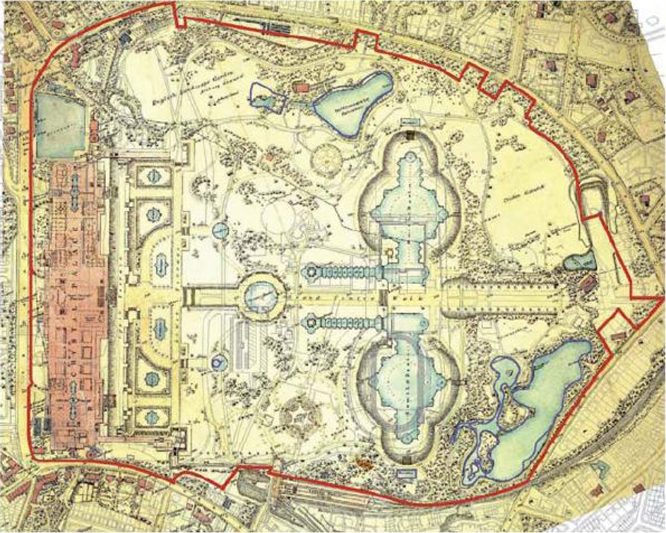
The path that led from historical colonization of this sub-urban hilltop with a Crystal Palace at the precipice to a Beekeepers Institute nestled in the rubble created by decades of deterioration is simple- The beekeepers have the opportunity to return the site to a landscape of buried artifice and rubble capped by sandy soil mounds. Marine Pines will indicate acreage that has been backfilled with deteriorated historical refuse while deciduous trees populate the remaining unaffected landscape.
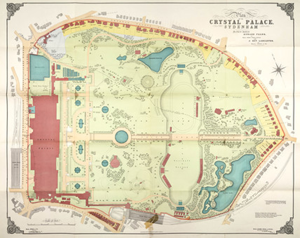
After the relocation of the palace from Hyde Park in 1864, the grounds saw an accumulation of additional buildings over time. This process of accumulation began after 1911 when the various interest groups in the park started to populate the hillside with buildings that were indiscriminately located. Slowly, the majestic palace's commanding presence over the terraced landscape became subjugated by mediocre brick buildings.
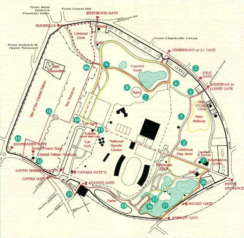
Eventually, the Crystal Palace caught fire and burned to the ground in 1936. The debris from the fire was extensive. By this time, many of the auxiliary brick buildings had fallen into disrepair also. And so, nearly fifty years after the extensive grading that fashioned the terraced parkland was started, a second phase of earth moving and debris burial had commenced.
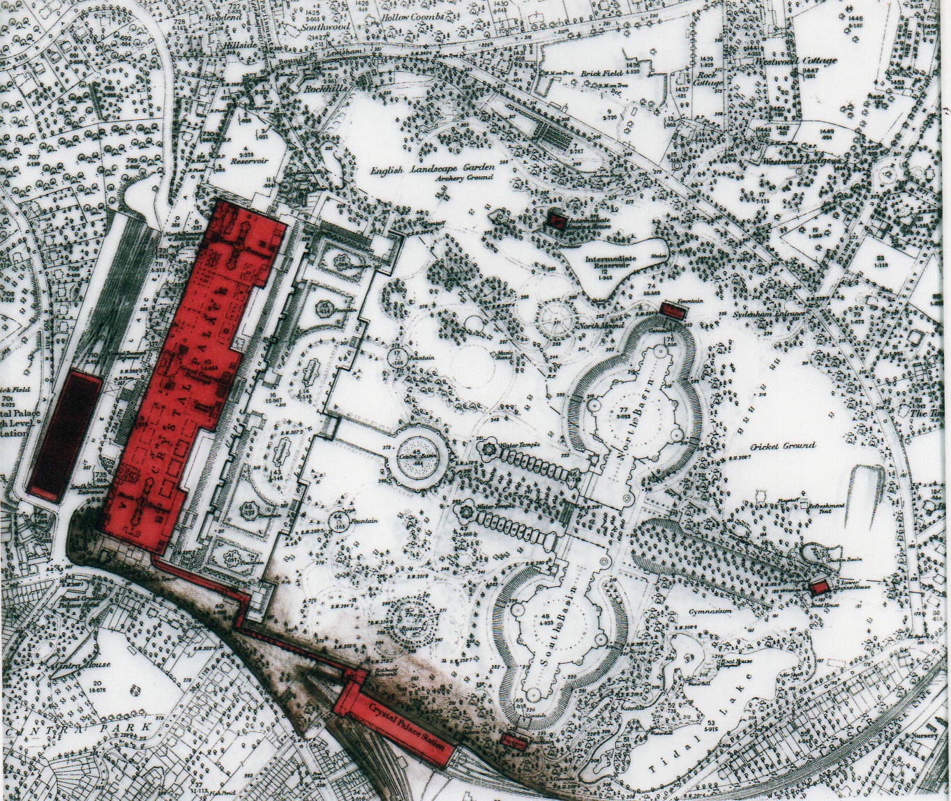
The brown shading on this sketch, and the subsequent series of sketches shows the iterative accumulation of landfill, backfill, and debris over a period of fifty years. The competing interests who wish to recolonize the park after such a long period of deterioration are learning that there is synergy with the unruly topography of yesterday.




Beekeepers' Institute Programming and Schematics
Beekeepers in South East England are more numerous than beekeeping populations in other countries. And why is this? Beekeepers in Southeast England have day jobs. By maintaining a day job, these beekeepers can devote themselves to their income by day and to their bees by night and on the weekends. Many beekeepers take personal time off in order to improve the lot of their bees.
Gven this level of passion and devotion, Londoners who are beekeepers have very specific requirements for their beekeepers Institute. Owing to the fact that many beekeepers time is so scarce, many beekeepers elect to stay at the Institute during week long periods of personal time off from their day jobs in order to make a meaningful effort of maintaining their bees.
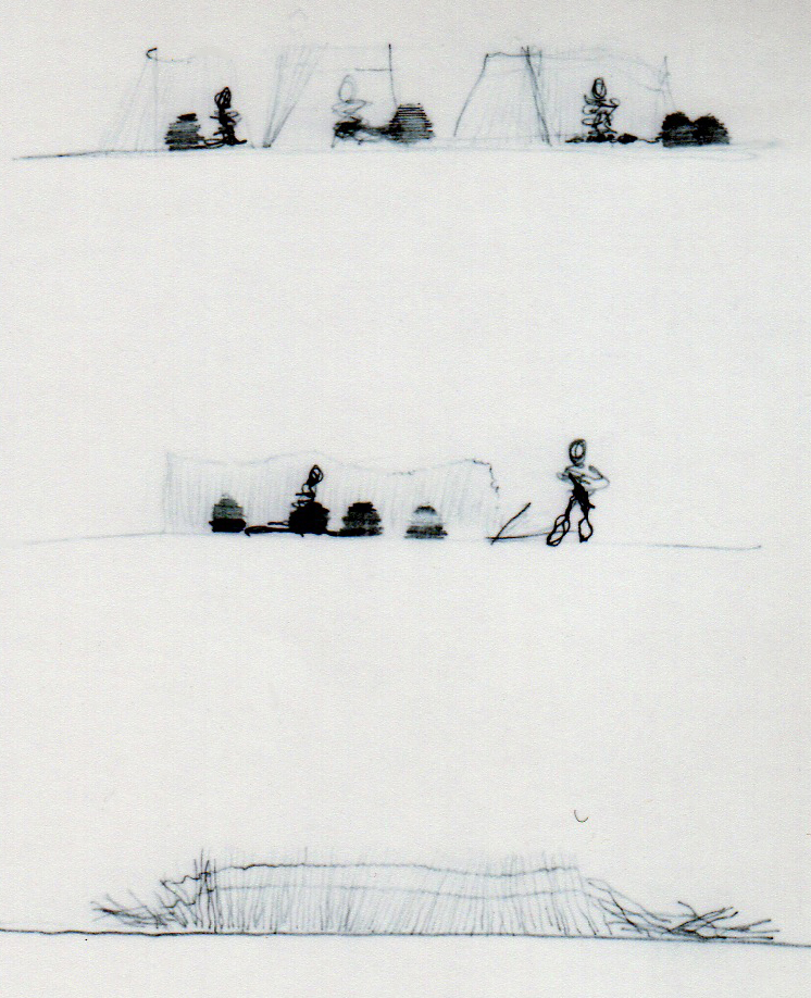
Skep Maker's Retractable Shelter- a place where straw matts may be woven and dried- out of the rain.
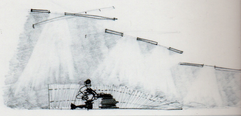
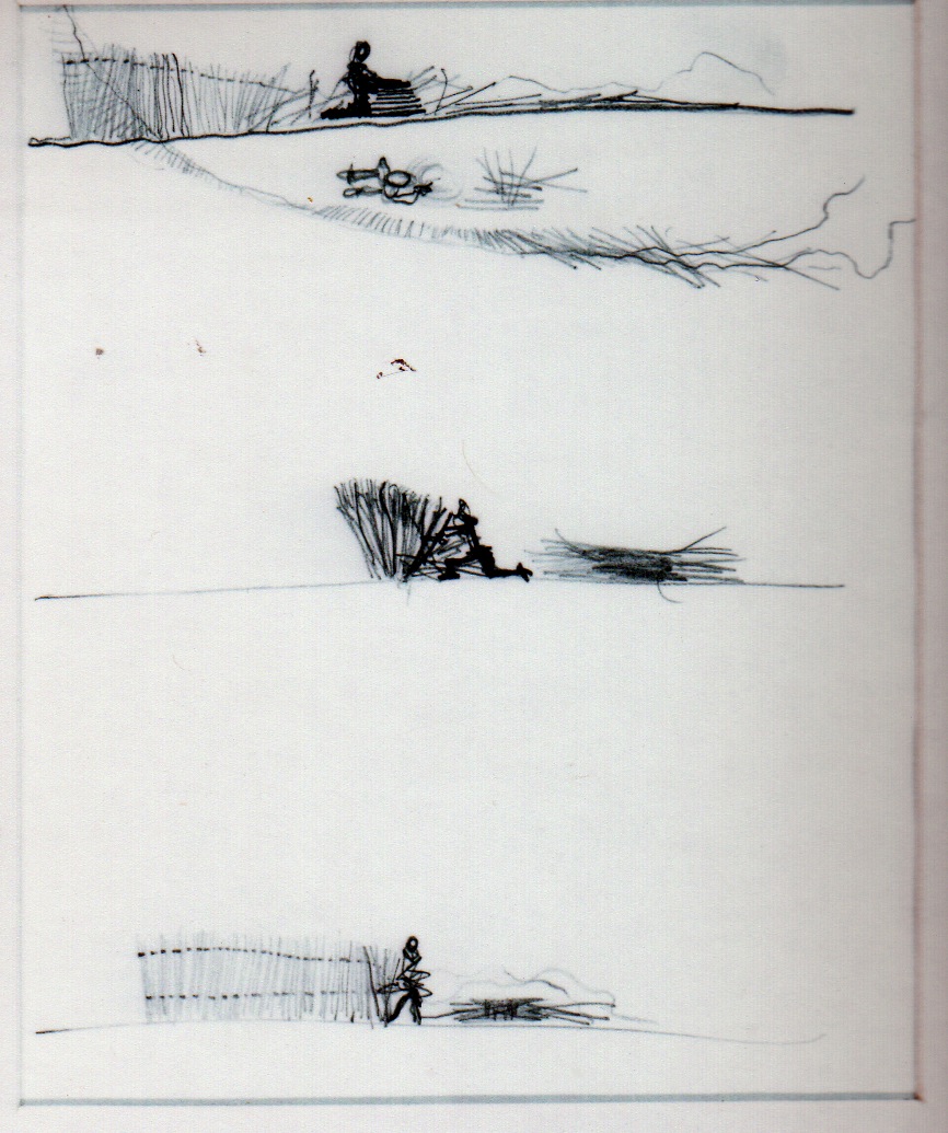
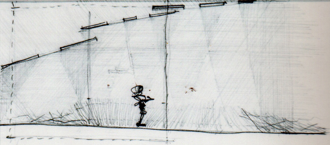
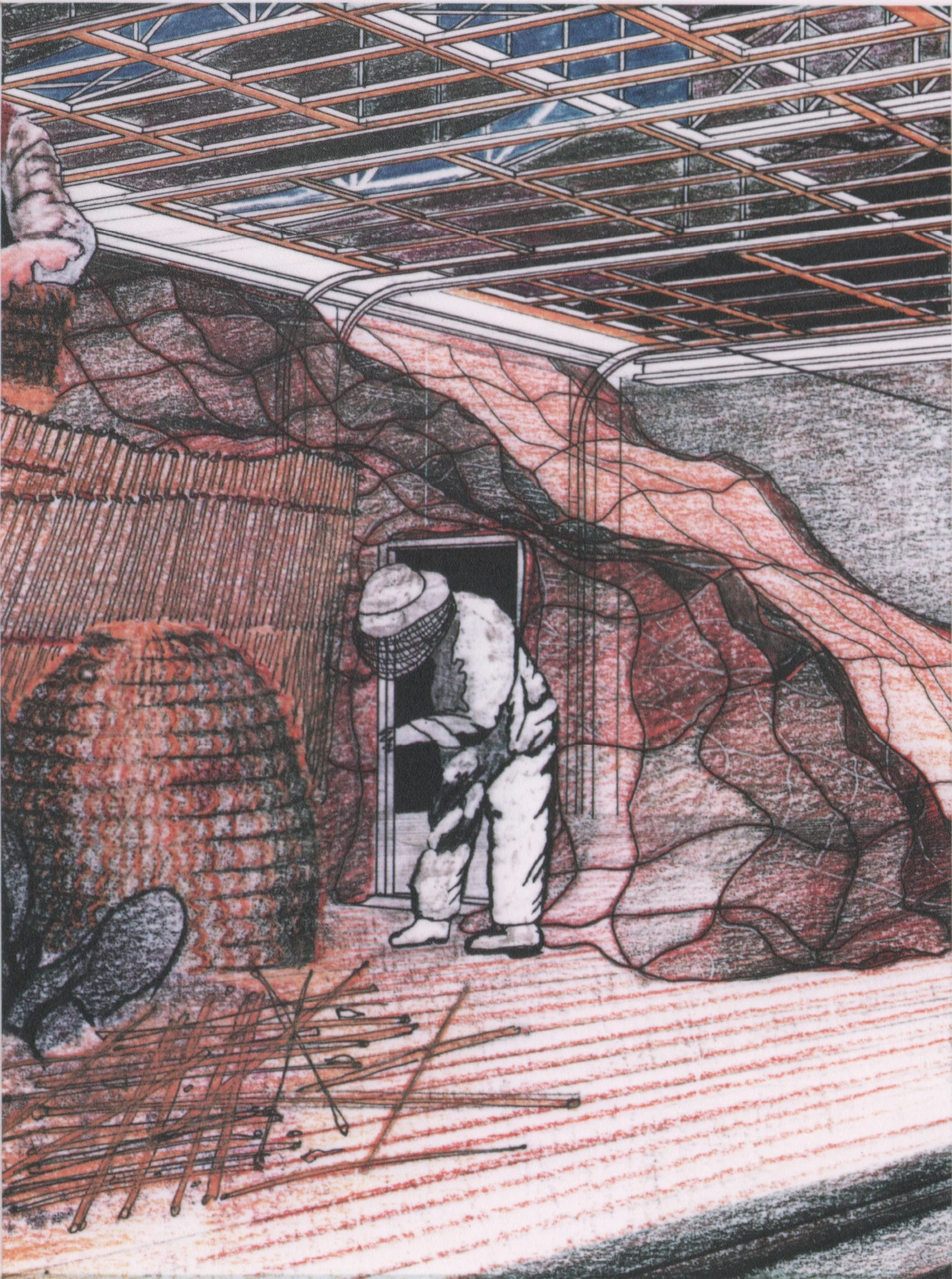
One of the programmatic functions of the Beekeeper's Institute is the creation of an indoor/ outdoor space that will serve as an activity space that can provide shelter from the rain at times, and provide access to sky for the bees that may be part of that activity when the weather is fair. This space became formally known as "The Farmyard" in the proposal. The Farmyards occur as stepped thresholds that can be covered with retractable canvas aprons during the winter months to store dry goods such as Skeps and wooden bee boxes and straw material used by the SkepMakers to make Skeps. There is also a thought that these farmyards can serve as shelter for bees in the winter and that these spaces will provide for protection against parasites and predators by maintaining a clear floor surface that is impregnable to intruders. Each BeeMaster has his / her own thoughts on winter care for their bees.
The activity of making skeps is a historical activity that uses straw-dried in vertical matts and then removed from the matts once dried. The dry straw is then woven into basket-like vessels for the introduction of a bee colony. This method of keeping bees is used by beekeepers who want a simple home for their bees and don't plan on extracting the honey from the bees. Often, these skeps are colonies that are used to maintain a more hermetically sealed enclosure that is more disease and parasite resistant place to build a population of bees prior to removal of the queen for queen rearing or for consuming honey on comb, which retains many of the natural antibiotics that bees build in to the hexagonal homes for their young.
The Heart of The Beekeepers Institute- The BeeMaster's Cabins (Farmhouses)
During Evenings and Weekends, Beekeepers take up residence in their cabins where their allotment of bee hives is cared for either in the farm yard, on the plateau or on the teaching platforms of any one of a number of live bee demonstration classrooms. The BeeMaster's Cabins are provided by the Institute for reservations over a period of time determined by the bee keeper's proposal. Most beekeepers stay in the cabins one night per week. If they have a more involved activity to accomplish, they may stay as long as one week. Two of the cabins are dedicated to resident scientists who have parallel foci- one is botanical and the other is entomological.
The BeeMaster's Cabins and the associated Farmyards serve as teaching centers and demonstrations for the public, workshops with tools for the individual BeeMasters where they may assemble their bee boxes and frames, and as a place where the SkepMakers may assemble their skeps out of the rain.
Auto Parts Distributor by Day, Entomologist by Evenings and weekends:
The entomologists who specialize in Honey Bees have a family auto parts business as their income and also are PhD Scientists by degree. Their research relates to the phenomenon of communication between bees. In order to research this, a completely dark room the size of a small garage is required to simulate the interior of a bee hive/ bee colony. It is in this space that a colony of bees are temporarily housed in a space that is large enough to contain the entomologist and his equipment as well as the bees.
The space rendered in the sketch which resembles a large sleeping bag inside a garage is the concept for this space where the entomologist has electronic equipment that simulates the dance of the honey bee. The entomologist's robotic, electronic bee performs a similar dance to the honey bee dance and communicates the distance, direction and type of forage of the location of food that is of interest to the bees. The entomologist then captures video of the same (marked) bees arriving at the where they are rewarded by the presence of the same food (nectar and pollen). There are other experiments that the entomologist performs in this space which evolved in the design of the Beekeepers Institute into the "Farmyard" which is a space that can be covered with canvas to provide shelter from the daylight and rain.
The Farmyard is visible in the plan and sectional views of the 1:50 Model photos at right. The Farmyard is essentially a multi-purpose space that provides the following purposes at a minimum; 1) Bee Hive Winter-proof Locations, 2) Instruction Classroom, 3) Entomologist Laboratory, 4) Nuke Zone- Space for building small young hives, 5) Temporary Outdoor Storage, 6) Decanting Space for BeeMaster's Cabin, 7) Access from the Institute to the Plateau.
The construction of this Farmyard space uses Core-Ten Sheetpile, Chemical Railroad Sleeper Timber Terracing, Galvanized Pipe Guardrail, Ferro-Cement Pavement Lights, Light Gauge Galvanized Corrugated Sheet Metal, Aluminum Framing and Glass. These materials are detailed in such a way as to be consistent with the rest of the design of the Institute which employs all of these materials to enclose spaces that are applicable to other activities in the Program of the Beekeeper's Institute.
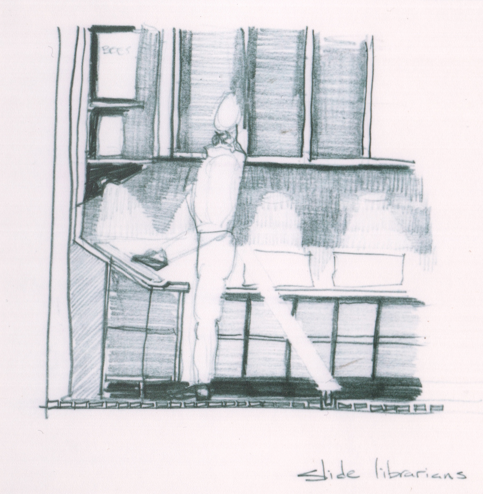
Stationers by Day, Beekeeper's Institute Slide Librarian by Evenings and Weekends:
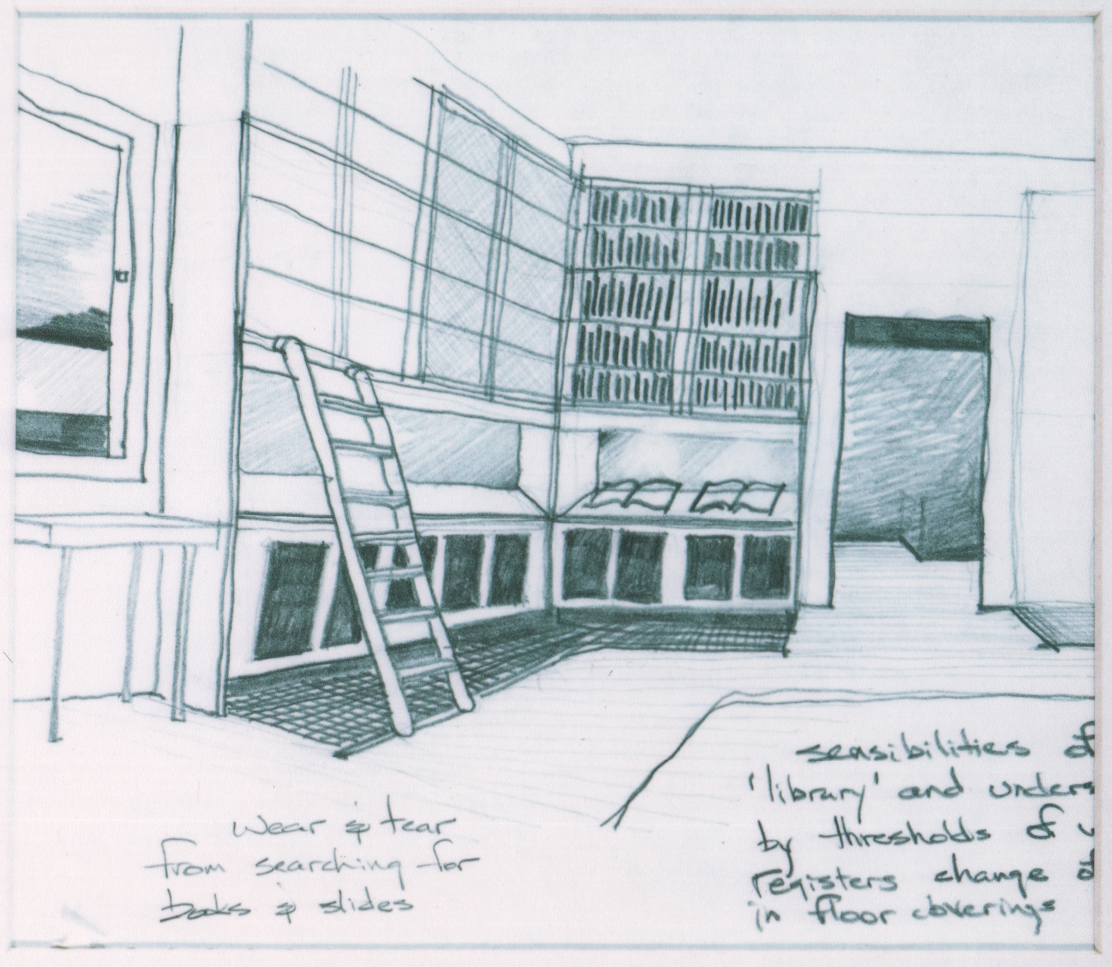
One of the unexpected by-products of the Beekeepers joint efforts is the creation of over one hundred thousand photographic slides (pre-digital age) that require storage and recovery from a library based in the grounds of the Institute. This space is frequented by members of the institute for lectures, as well as research. The activity of scanning these slides for electronic storage is also common in the slide library as is maintenance of the institute's web server.
The Slide Library is one of several spaces in the Beekeeper's Institute that does not require protective clothing in order to access the many drawers of slides in it's casework. The space has a significant amount of natural light and is attached to the Institute's Book Library. It is a double height space with cases full of catalogues that identify the slide location and content. There are views out of this double height space that see out to the park and over the cascade of roofs which increasingly turn themselves up as the roofs become part of the live bee activities and the eaves slope up so as to prevent the bees from getting trapped.
Q: Why do the roofs of the working bee buildings slope up?
A: Bees get trapped under down-turned eaves. This is a common confusion for a bee who believes that the only solution to entrapment is to fly up. Hence, the Institute's buildings, which become more alive with bees as the Institute continues further into the Park- these outpost buildings' roofs become more inverted as a result. This is visible as a curious feature of the design of the institute and also happens to coincide with the increasingly unruly topography of the park which is the result of the landfill component of the planning and site design of the Park's re-design. While standing on either of the two Plateaus, this changing geometry of the Institute's Roofs is evocative of the beating of wings and is also caused by the beating of wings on a much smaller scale.
The long cantilevers that the roofs extend over the teaching spaces are two-directional sandwiches of corrugated, galvanized, sheet metal that have a core of spray-on insulation identical to that of the exterior wall construction.
Q: Why don't the buildings just sit on top of the landfill? Why are they clipped onto the side of the landfill mound?
A: The creation of "rules" that govern the introduction of new buildings in the park involve using new construction to help create park thresholds. These thresholds create more interaction with people entering and leaving the park. The buildings themselves also become more a part of the land at the margins of the park, allowing the park to be about the landscape rather than just a "greenfield site" for architects to reduce the park to a sub-urban subdivision. By contributing to the overall effort of landfill retainage and slope stabilization, the new buildings allow the open spaces of the park be dedicated to temporary structures such as beehives on the plateaus and other natural landscape features such as trees and meadows. There is also a historical precedent and rational for treating the debris removal as did prior generations.
Commuter Train Driver by Day, Beekeeping Lecturer during evenings and weekends- The Lecture Hall is a space that allows observation of Live Bee Demonstrations:
The Lecture Hall is a multipurpose space located on an elevated level just inside the entrance to the Institute and it has an observation portal that allows for visual instruction of live bee demonstrations being performed by instructors with an audio link to speakers inside the lecture hall. This observation portal is hermetically sealed from the environment outside and provides views of the park in the distance, beyond the plateau where the instruction observation takes place.
The lecturer also may depend on a multi-media presentation and darken the room for such presentations. The botanist, who lectures on species of plants that would not exist were it not for bee pollination presents plants in realtime in the lecture hall and maintains them in potted plantings on the plateau adjoining the Farmyards.
BeeMaster's Shed- "A busy Farmhouse", a place where beekeepers can compare notes.
Activities can involve the use of power tools including table saws. Therefore, three phase electrical service is available at each of the farm houses. The only water supply available at each house is for potable water. Showering and sanitary facilities are available in the main part of the Institute in the locker room. The farmhouse is Spartan in nature, each has food preparation and a study table in the sleep space on the upper-level. Members of the public on the plateau can walk over to the farm yard areas and witness the activities going on below from the guard rail. Naturally, the presence of many honeybees will be a deterrent to people with allergies. Discrete signage at the periphery and the entrances to the plateau will warn people of the presence of bees similar to keep off the grass signs. It is possible to descend down into the farmyard from the plateau on retractable stairs not shown in the model. The guard rail at that section of the retaining wall is also removable.
NewsAgent by day, Pollen Collector and Bee By-Products on Evenings and Weekends.
Rajiv works at Brixton Tube Station at a NewsAgent that he owns. At night, he often rides the No. 3 Bus to Crystal Palace where he collects pollen from bee hives at the Beekeepers Institute. Pollen is considered by many eastern cultures to be a sacred substance. Scientists have discovered that pollen contains antibiotic properties. In addition to pollen, royal jelly is also considered to be a substance that contains wellness properties. In order to extract Holland and royal jelly and beeswax from the beehives, Rajiv has to work very hard in cooperation with the other beekeepers. His harvest has to be stored in food grade containers in a dry and cool environment. The sketch shown to right shows vaults that are properly waterproofed with a vapor barrier and a waterproof membrane that are kept at a naturally cool temperature thanks to being below grade. The honey bee by-products are packaged for sale at the Bee Products retail shop shown on the plan above.
The Plateau- single-story buildings protrude above the level of the plateau.
In all cases, single-story extensions of each institutional building rise above the level of the plateau and present a subdued elevation. The presence of guard rails at each farmyard also define the area at the periphery of the plateau. In the case of the farmhouse, there are two doors. One door leads into the sleeping space on the upper level and the other door leads to a stair which goes down to the lower level. These doors are protected from the weather by a continuation of the roof visor. There is a skylight in each roof. In addition, there is a pavement light at the threshold to each pair of doors that allows light into the lower level. Rainwater is collected and scuppered off of the inverted eaves and recycled into rainwater drums.
Enlarged Sketches Below:

The Beekeepers Institute consists of many functions and spaces, some multi-purpose and others dedicated to the study of, exhibits for, discussion and demonstration of bees and bee products, including apiculture and agriculture that depends on the activity of bees.

In England, one honorable occupation is the construction and care of the railways in the realm. The boundary created by railways often results in thick natural buffers that become overgrown with old growth trees and are secluded places where bees are prone to swarm and grow new colonies. Railwaymen have been known to reconnoiter with the bee swarms, facilitate a new home for them and to do that using a bee hive known as a Skep.

In order to allow the Beekeeper to sleep and study and prepare food in her spare time, she must climb up to the horizon level room at the plateau where a manicured landscape forms her front yard. Her front door opens into a skylit space that egresses stray bees through operable glazing. During her workday, there are members of the public who eagerly watch her work with the bees, taming them and teasing out of their hordes a specimen of honey, a queen to be reared, a crop of pollen to be processed, a dose of royal jelly.

Auto Parts Distributor by Day, Entomologist by Evenings and weekends, he communicates with the bees (as seen on National Geographic).

Two hundred years of debris lies beneath the timber floor of the farmyard. The sand, the rip rap from the demolished exhibition buildings, the expansive clay, the excavation of the early Victorian landscaper, and, the London Basin layer itself. Above grade, the ephemeral activity of beekeeping, and the boxes of bees themselves are an attempt to understand why the bees are becoming extinct.

These volunteers, who staff their stationary store by day- also provide librarian expertise at the Beekeeper's Institute during the weekend and evenings. Beekeepers are allowed to trawl through the drawers of slides and borrow images of bees, their parasites and their habitat in order to confer with lecture hall packed crowds as to what may be causing colony collapse disorder and quite possibly their extinction.

The progression of busy bees from the back of the institute where the beekeeper's cabins meet the Crystal Palace Park to the exhibition space at the from of the institute where the public will enjoy air conditioned, bee free, indoor space is visible in the architecture of the roofs. The calm, flat roofs of the exhibition space don't require the animation of the upturned roofs in the active bee keeping areas of the back areas near the park. The increase in flapping wings in the institute as public becomes more private allows the bees to avoid getting caught in the eaves where they are more prevalent.

The Beemasters cabins engage the edge of the landfill plateaus. All of the permanent architecture of the beekeepers institute follows a pattern of engagement of the topography. The temporary structures such as the beehives , The bee skeps and the bee boxes are placed on top of the plateau during the summer months. These are the only structures that are sited on top of the plateau. All other structures engage the edge of the plateau just as the rail station and other surviving structures from the Crystal Palace.

Albert Einstein once said, "If the bee disappeared off the surface of the globe then man would only have four years of life left. No more bees, no more pollination, no more plants, no more animals, no more man."
"If the bee disappears from the surface of the earth, man would have no more than four years to live".

The two buildings at the end of each plateau of the Beekeeper's Institute provide for a total of four resident beemasters. They live in these utilitarian split level metal hermitages that are abuzz with activity all summer. The public who wander onto the plateau can gather around the balustrade and watch the beemaster drive his bees.

One safe place to store honey and pollen products is underground, behind hermetically sealed doors. The ripening halls are designed for this purpose and the indian gentleman who owns a newsagent also provides the institute with collection of pollen and royal jelly for retail sales out of the Honeybee Products Shop next to the slide library.

The edge of the landfill plateau is engaged by all of the permanent buildings of the beekeepers Institute. Here, the Beemasters cabins rise above the edge of the plot and provide access above to the private quarters and below to the resident bee master's workshop and lecture platform.

The Skep Maker's weaving shelter is a purpose built space that allows for the straw to be woven into weaving matts to dry. The shelter is clear of rainfall and allows for the weaving matts to vary in length and location. Once the weaving matt is dry, the Skep Maker unravels the straw and bundles the straw into clutches of rope-like material which is then whirled into a Skep for a small bee colony to store honey and grow brood.
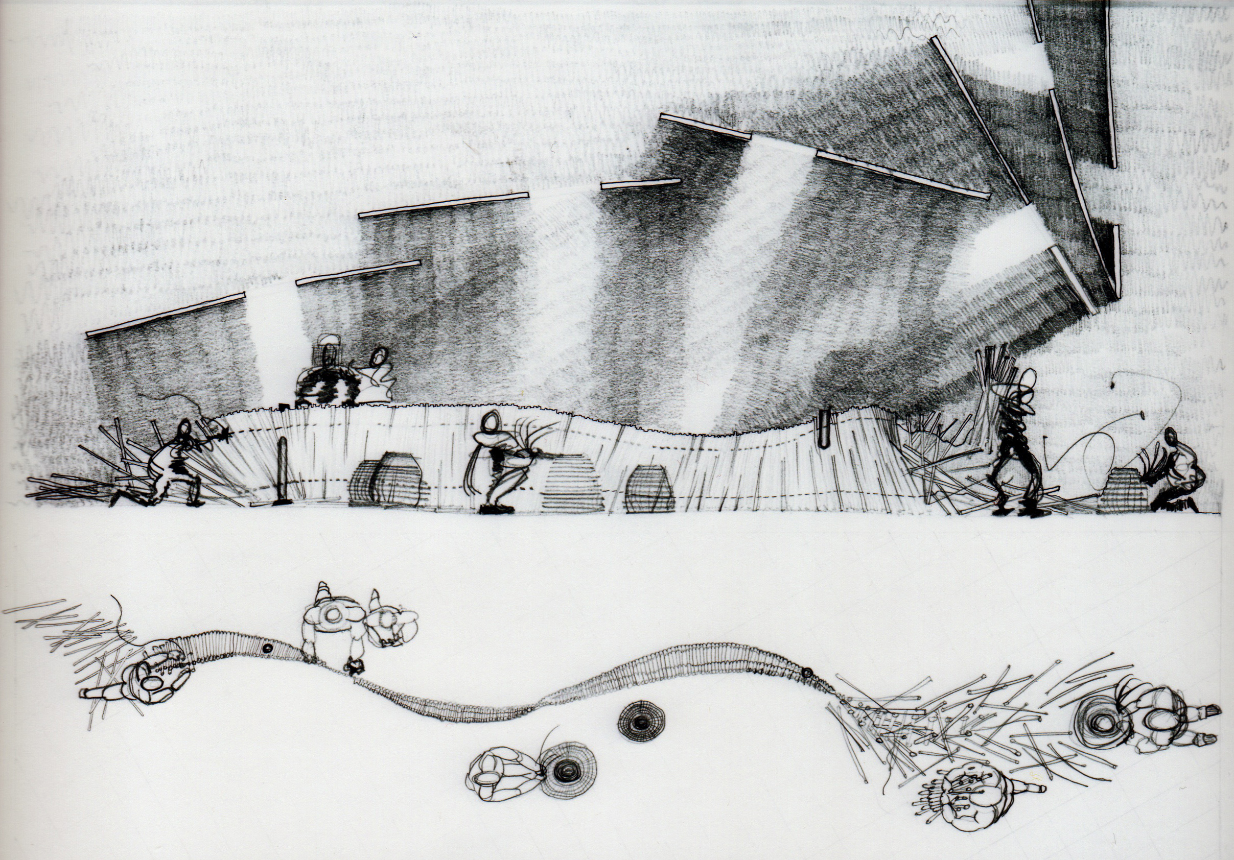
This unusual space, which is able to shelter activity of weaving and the dry straw used for the construction of skeps. The motion of people under the skepmaker's awning is constantly changing, depending on where the dry straw is being unfurled. This space is seasonal and provides storage in the winter as well as a place for the equipment to be kept dry during the rainy season.

One of the activities at the Beekeeper's Institute is Skep Making. This is a historical activity that uses straw-dried in vertical matts and then removed from the matts once dried. The dry straw is then woven into basket like vessels for the introduction of a bee colony.






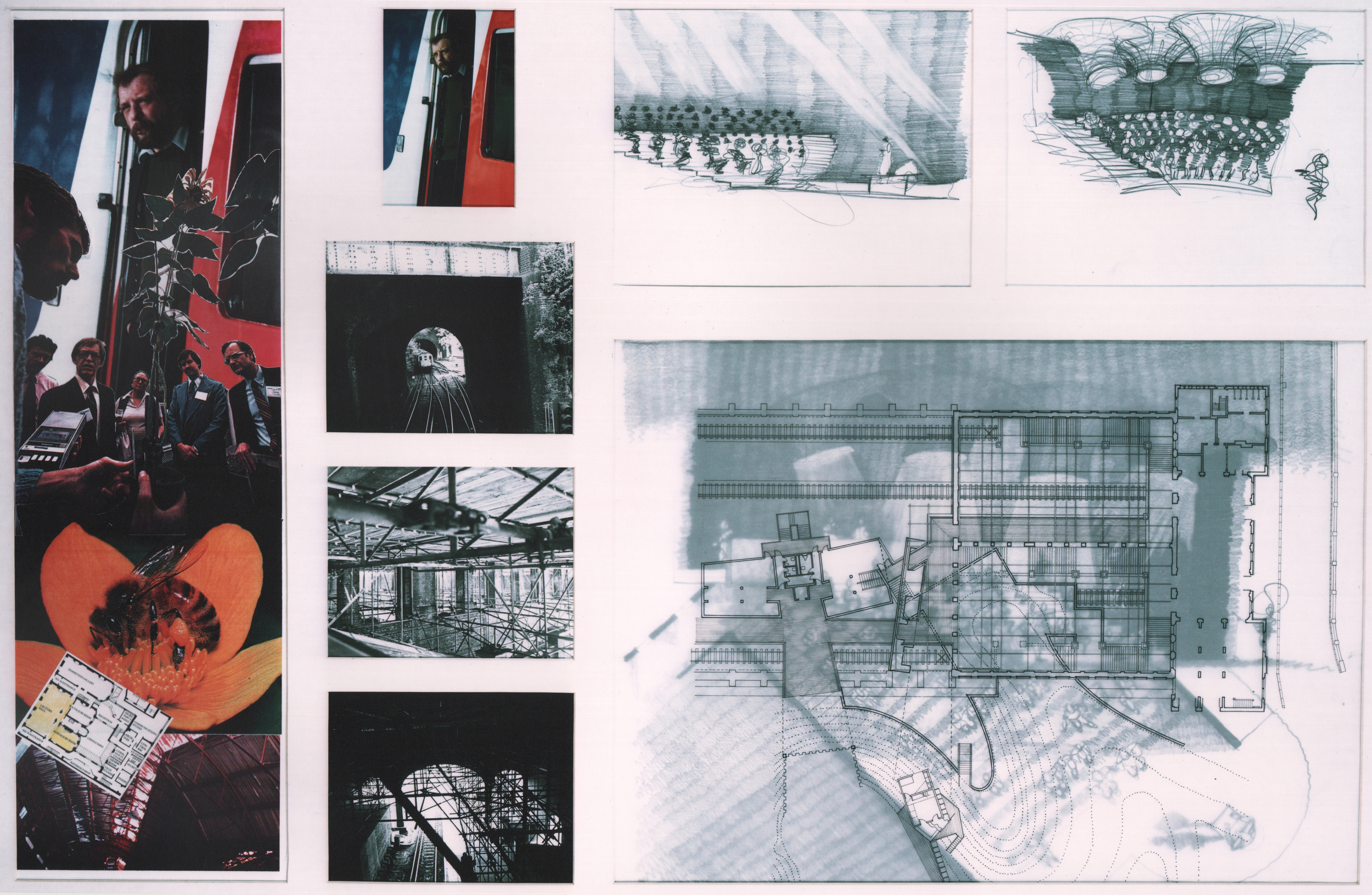






Beekeepers' Institute Design Development and Narrative
Project History
-Started as an academic project in Diploma School of The Architectural Association School of Architecture, London
-Tutors; Peter Salter, Jeanne Sillet, Leon Podlubny
-Project evolved into a live, professional historic preservation project that interrupted the academic work from 1990 until 1991. (see Low-Level Station)
-Work on the Beekeeper's Institute recommenced in 1992.
-Project was completed and submitted (passed) for Royal Institute of British Architects Part Two and the Architectural Association School of Architecture Diploma in June 1993.
Inception-
The Beekeepers Institute project is a 1989 project that started out as a House for a Family Member which happened to be my father-in-law, a life long beekeeper. My father-in-law taught my wife and I how to care for his bees that year. Prior to the completion of the project, my father-in-law would be struck-down by acute myeloid leukemia. His beehives would become my wife's inheritance and we moved the beehives from his home in Leicester, England to London where we had a house with a flat rooftop in Brixton. His death would provoke a visceral response from the effort to design the project. In addition to these four very large beehives, with all of their citizens who would become new members of our family – my wife was with our first child during this time. Therefore, while the inception of the project included the death of my father-in-law, it also coincided with the birth of many tens of thousands of new bees on the roof of our Brixton home as well as the birth of our first born, Daisy Louise Millard.
Prior to his death, initial designs for this "House for a Family Member" were presented to my then tutor, Peter Salter. Peter greeted the project with great enthusiasm and after seeing the culture, technology and history of beekeeping (with all of its eccentricities) he determined that the brief for the project warranted a project of institutional scale rather than residential scale, due largely in part to the rich content that defined the world of the Beekeeper. At that time, in the early 1990s – there was no existential threat to the honey bee as there is today due to colony collapse disorder. England in 1989 was still a safe-haven for honeybees who were being decimated by the Varoa Parasite in Europe, the United States and elsewhere in the world.
My father-in-law agreed that the opportunity to design an entire beekeeper's institute (albeit academic in nature) for my thesis would more comprehensively promote the craft to anyone who would listen and offered to be my technical advisor for the beekeeping subject matter expertise. Therefore the early studies for the BeeKeeper's House became superseded by new studies for a Beekeeper's Institute.
Site Selection-
Therefore, the effort to select a site for the project commenced in earnest. I had just completed two "sandwich years" working as an intern at Arup Associates in Soho Square. There, at Arup, I had carried out extensive studies of a South London Site known as The Crystal Palace Park. A wealthy Kuwaiti client of Arup was contemplating an investment in The Crystal Palace Park by constructing a replica of the Crystal Palace and occupying the new building with profitable activities similar to a Disney Theme. Therefore, the Crystal Palace Park became a target of my site search.
Within the Crystal Palace Park were many of the suburban / urban edges that I had explored with my Public Footpath Folly from an earlier Diploma School Project at the Architectural Association. The geology of Sydenham Hill itself was characteristic of the London Basin (discussed in "Public FootPath Folly Strategy") since the hill was the last of the "Great South Downs" which rippled up from the south coast of England from Brighton. This hill that once overlooked the whole of the London Basin with a Crystal Palace was now echoing many of the properties of the Lea Valley discovered on the Public Footpath Folly. Therefore, I settled on this site knowing that I would be able to express many of the same goals from the Folly Project in a "serious" piece of architecture, rather than a folly.
While working on the site development of the Crystal Palace Park for Arup's client, the resources of the firm came to bear upon the project with aerial photos, topographical maps, literature, historical research, multi modal transportation studies and other collateral consultant material was accrued for the benefit of due diligence on the project. Sufficeth it to say, I learned a great deal about the Crystal Palace Park from this material and was about to borrow from this reservoir of information to facilitate my thesis project, the Beekeepers Institute.
Site Strategy Takes Shape-
I quickly focused my efforts on the southern edge of the Crystal Palace Park largely due to the pre-existing artificial edge created by the Crystal Palace Low Level Station, the rail cutting itself and the cut and fill excavation that resulted in the unruly topography of backfilled retaining wall of the rail station. It may have been this initial excavation for the reconstruction of the Crystal Palace that relegated this southern boundary of the Park as the "dumping grounds" of the Park. For after the initial cut of the rail station in 1874, debris from all kinds of demolition and deterioration was deposited here, resulting in high strangeness of topography. This is how the design of the project became such a landscape emphasis, owing most of the plateau creation to the tradition of demolition. As for the idea of establishing rules of engagement for constructing buildings in this context, these came from the Public Footpath Folly (a metaphor for London basin).
The Crystal Palace Low Level Station itself was very deteriorated and derelict. It was very fashionable in certain architecture schools to "intervene" within the context of a derelict building so that the proposed new construction can "inhabit" that derelict structure and resonate with it in some way. I initially fell prey to this concept, preparing many sketches and models of possible "interventions" within the Crystal Palace Low Level Station for discussion with Peter Slater, my tutor at the Architectural Association School of Architecture. Peter expressed skepticism initially of this approach, concerned that the Victorian context of the Rail Construction could disproportionately dilute my proposal with brick arches, cast iron tension rods, timber roof framing and Ruskinian filigree. At the next tutorial with Peter, he declared that I might have taken his hint that intervening within the rail station would be frowned upon, and as usual, he had to spell it out for me- "move your project out of the rail station for progress toward a proposal fitting for a thesis project".
Tennant of Rail Station requests professional architectural services –
Nevertheless, while I had been discovering the Low Level Station, sketching it's elevations, photographing the retaining walls and taking some as-built measurements- I was discovered by some tenants of the Low Level Station's booking hall (the only habitable space in the building) to have expended more effort on my pro-bono student work than had their architect whom that had paid handsomely to prepare a development proposal for planning review. These tenants were two ex-Southeby's Art Auctioneer types who regularly held estate auctions inside the booking hall of the Low Level Station. They seemed interested in my work and they fired their architect. I would later (in 1995) be accused by RIBA Part III examiners of a breach of Royal Institute of British Architects Code of Conduct Violation because, technically, even though I was a student working on my thesis project at the time. The examiners told me that I should have made sure that the pre-eminent architect was paid his fees and I should have confirmed this directly with him. Being as I was not licensed yet as an architect, nor cognizant or subject to RIBA Codes, there was no chance of that happening and so they failed me at my first RIBA Part III Certification Hearing in September 1995. One month later in October 1995, my previous boss at Arup, Richard Frewer who was also Dean of the School of Architecture at the University of Bath admitted me to the Bath Chapter of the RIBA Part III Examination Course which resulted in a positive certification result for me after re-taking their exam, resubmitting my case study and re-interviewing with the Examiners in Bath.
So, back to the 1989 time frame- my tutor had just aborted my proposed thesis design which intervened within an English Heritage Grade 2 Listed Historical Rail Station by Joseph Paxton and by exploring this option managed to piss off the establishment London Chapter of the RIBA by attracting clients who fired their architect (who waited six years to falsely accuse me to the RIBA of an ethical violation). I then returned to my student proposal in 1990 after preparing some as-built drawings of the Crystal Palace Low Level Station for British Rail and English Heritage, a labor of love and a not good deed gone unpunished. For a view of these drawings, see Historic Preservation Project at Crystal Palace Low Level Station elsewhere on this web site.
More on Site Strategy-
The southern boundary of the Crystal Palace Park became an intrigue because of the history of landfill using debris from the demolition of the Crystal Palace in 1936. Extensive discussion about this aspect of this site is thoroughly presented under the "Beekeepers Institute Strategy". In addition to this narrative it is important to point out that the situation of the Beekeepers Institute within the modified grounds of the Crystal Palace Park is not only a metaphor for the London Basin, (with many of the attributes of the Public Footpath Folly), but also has attributes accretion or those qualities that are indicative of a growth or a tumor that has grown (not plopped down) into an existing context with the self locating specificity of a hand into a glove or a glacier into a valley (or a swarm into a hollow).
The Beekeeper's Institute is a building that has achieved many of the site objectives of the "Institutional Edge" that are desired to be created along the southern Boundary of the Crystal Palace Park. This "Institutional Edge" is comprised of a dozen or more Park institutions that are resurrected from the rubble of demolition that has occurred in order to implement a site strategy that creates thresholds into the park using these new institutional buildings such as the Beekeepers Institute. The threshold that is created by the Beekeepers Institute is defined by two plateaus that have been created from landfill and conform to the footprints of existing historical debris deposition dating back to the Victorian era. A more lengthy description of this "unruly" topography is found in "Beekeepers Institute Strategy". These two plateaus which step down with the natural grade of Sydenham Hill, form a chasm that contains a path which leads down to the subterranean world of the Crystal Palace Low Level Rail Station where additional institutions such as the Train Spotters Institute and the National Railway Museum have their homes in a newly renovated section of the Low Level Station. These institutions gain visibility from their location at the railway platform where visitors to the park arrive to the site from Victoria Station in Central London.
Public Face of the Beekeepers Institute-
Aboveground, the Beekeeper's Institute forms an east-west edge with the community where a sheer face of heavy gauge "Core 10" steel sheet pile forms a retaining wall that retains the debris that has been strategically placed behind this wall in order to create the plateaus and the chasm into which the Beekeepers Institute has been situated. This aboveground manifestation of the institute appears in the form of a public entrance to the Institute. At the point in this large steel retaining wall where the chasm occurs, the public face of the Institute projects itself using a large opening that defines the entrance using glass and the lighter gauge corrugated metals that make up the building language of the rest of the institution's buildings behind the wall. All of these Beekeepers Institute buildings are designed to act as retaining structures for the landfill debris in order to create the chasm. This threshold, through which passengers who wish to enter the park directly from the rail platform- allows them to experience the bowels of the Beekeepers Institute from within the chasm approach into the landscape of the Crystal Palace Park.
Public Entrance to the landscape of the park from above and below –
It is quite safe to enter the park from the rail platform through this underground approach. The vast majority of live bee activity occurs at the plateaus above and within the farm yards and instructional spaces of the Institute above and there is little chance of getting stung by a bee by entering the park through the chasm. If one enters the Beekeeper's Institute through the public entrance above, then there is explicit signage that indicates the threshold beyond which the hermetically sealed public spaces of the Institute will no longer protect one from the congested environment of bee traffic in the teaching spaces of the Institute. These teaching spaces become more congested with bees as one progresses further into the semi private areas of the Beekeepers Institute. These semi private areas of the Institute are the spaces which are occupied by the Bee Masters and Resident Bee Keepers who reserve these spaces at various times during the year and have a permanent waiting list of determined members who wish to occupy the Institute in order to advance their agenda. Airspace within these areas are so congested with bees that the roofs begin to "turn up" so that that down sloping eaves do not entrap the bees. This phenomenon of enabling the bees to escape from under the building roof explains the odd configuration of the roof canopies as one progresses further back into the Institute where the Bee Masters' Farm Houses have the highest concentration of air-traffic.
Nevertheless, the public spaces of the Institute have a number of opportunities for the members of the public to safely view the exhibition of honeybee history, technology, care and cultivation. There are also observation areas where members of the public can witness the manipulation of entire honey bee colonies by beekeepers in real-time from within the hermetically sealed spaces of the institute's live bee lecture halls. These lecture halls also contain observation hives which are hermetically sealed from the climatologically controlled spaces of the lecture halls. Here, a visitor to the Institute can witness the movement of bees across their brood comb, where the queen bee is laying eggs and worker bees and nurse bees are cooperating together to build a veritable civilization. Several of these observation hives are built into the wall section of the institution. The use of metal as a cladding strategy enables the tight tolerances of construction to keep the bees out of the public space.
Project Design-
The design is nearly as much about the design for a land fill project as it is for a Beekeepers project. Why is this? Well, history of landfill in the Park is a strong reason...but that is not the only historical reason. The primary historical reason for:
- demolishing all of the buildings in the Crystal Palace Park, (except for the National Sports Center),
- pulverizing the remaining building fragments an depositing the debris on traditional dumping locations in the park,
- and siting new institutional buildings on the edges of those debris mounds where thresholds can be framed of the entrance to the park,
...is that the Crystal Palace Park was an oasis of civilization (surrounded by countryside) as opposed to suburbia in the 1870s in what then was far south of London. We often



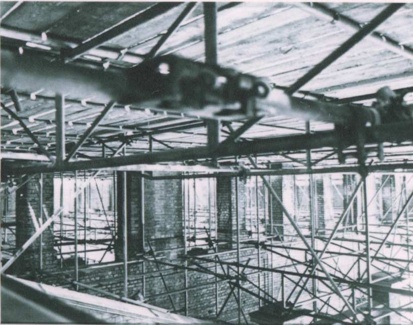
Mounds of landfill have been caused by a century of demolition of building remnants from The Great Exhibition of 1854. The rules of constructing new buildings have to do with retaining the fragments of yesterday by engaging the edges of these unruly topographical aberrations. Man-made mounds have been aggravated by addingcontemporary demolition of all superstructure on the site except for the National Sports Center.







Folly for a Fence: Public Footpath from Suburb to City
A folly for a fence-
Public footpaths in England often can be found following the rivers. It's easy to forget that our city was conceived from the need for water. The London river basin is comprised of several rivers, The Thames, with it's tributaries The Rivers Lea, Colne, Crane, and the River Brent, and Right Bank Tributaries including the Rivers Mole, Wandle and the Ravensbourne. Many suburbs of London derive their names from the rivers. People's addresses are water-based place names. This goes on without people being cognizant of how the impact of water has affected their identities and their origins.
What's interesting about a Folly for a Footpath is that the edges of The Basin are where the great reservoirs of water are located and the infrastructure created to contain these artifices are the first evidence of city as one approaches the city from the country side. Invariably, suburbs are formed around these reservoirs. Large residential concentrations of people to feed the industrial 'plant' with humans to work. It is the collision of people and 'plant' that essentially defines the edge of the city. The materials used to construct the infrastructure for these water worlds and how it affects the built environment in the London Basin come together in Folly for a Footpath.
The materials used to manage the water are impervious and utilitarian. The materials used to house the people are impervious and domestic. This is the Metaphor; crossing a fence that is the divide between the domestic, residential suburb and the utilitarian, industrial cityscape occurs as a public footpath stile/ folly located on the fence/ edge between these two worlds and celebrates the edge with cheerful laughter.
What is a public footpath stile?
The most ancient network of travel ways in England are the public footpaths. Landowners are required by ancient law to "refer to your responsibilities as the occupier for the provision and maintenance of gaps, gates and stiles on public rights of way where they cross your land. Remember:
as the landowner you are responsible for maintaining stiles and gates in a safe condition
poorly maintained stiles and gates may leave you liable for any injury sustained by the public attempting to use them
well maintained and clearly waymarked stiles and gates will help prevent people becoming lost and will mean less damage to boundary fences and walls.
Lawful stiles and gates
A stile or gate, although on a public right of way, is not a part of it. Such structures are for the advantage of the landowner, to permit enclosure of the land and to control the movement of livestock, rather than for the benefit of the public.
Therefore, stiles and gates cannot be erected on a public right of way at a landowner's or occupier's discretion. The public's free passage can only be interrupted by such structures certain circumstances:
where a stile or gate traditionally existed in a held boundary for many years and pre-dates recording the right of way
where we can authorise a new stile or gate. Under the Highways Act 1980, section 147, our powers as a county council are limited to authorising stiles and gates only where they are necessary for preventing the ingress or egress of animals on land that is used, or being brought into use, for agriculture or forestry.
note under s147ZA we have to have regard to the needs of people with disabilities when authorising structures
All gaps, gates, kissing gates and stiles should conform with British Standard 5709 where possible
Please note: agriculture includes horticulture, fruit growing, keeping livestock, grazing land, meadow land, market gardens and woodlands.
Existing stiles and gates
Do I have to maintain the stiles and gates on my land?
Yes. The landowner/occupier is responsible for maintaining all such structures on public rights of way in a safe and usable condition (Highways Act 1980, s.146). If you are a tenant the landowner may have passed the practical responsibility to you. If in doubt you should contact your landlord.
Can I replace an existing gate on a public footpath with a stile?
No, as this would normally result in undue inconvenience for the public. Generally the replacement of a gate with a stile will be more inconvenient because people will have to climb over a stile as opposed to opening a gate. If you are experiencing particular problems with people leaving gates open please contact your field officer (see help and advice at the bottom of this page).
Remember: You can replace a normal stile with a gate. Gates give much better access for the public and can be made stockproof.
If I remove a gate or stile and leave a gap instead do I retain the option to restore it at a later date?
Yes, the county council encourages the removal of stiles and gates where they are no longer needed for controlling animals.
Will the county council contribute towards the cost of maintaining existing stiles and gates?
Yes, a landowner is entitled to recover 25 per cent of reasonable costs incurred, but the work must be agreed beforehand. The county council's contribution may be in the form of labour to carry out the work using your materials.
Remember: Before you carry out any work you must contact your field officer (see help and advice at the bottom of this page) to discuss your plans.
Can I lock a gate on a right of way?
In most circumstances a locked gate would be an obstruction on a right of way and therefore cannot be permitted. However, if you are experiencing a particular problem then please contact your field officer (see help and advice at the bottom of this page).
Can I put a new gate or stile next to an existing gate?
You can do so, but it is an additional facility for the public. The existing gate remains on the definitive legal line of the path and must therefore be kept unlocked and available for the public at all times.
To what standard should my gates and stiles be maintained?
All stiles and gates must be maintained in a safe condition, so that they are easy for all users to negotiate, this includes the elderly and the less agile. Please read the 'practical tips' section below. The British Standard for public rights of way gaps, gates and stiles is BS5709:
Remember: There are many local variations which form part of the rural fabric of Oxfordshire. As long as they meet the basic criteria we would not expect them to be replaced with a more modern design. Traditional features, such as Cotswolds stone stiles, should be retained whenever possible.
Is there a minimum width for existing gates on public rights of way?
Yes, on a bridleway it is 5 ft and on a restricted byway or byway open to all traffic (BOAT) it is 10 ft. There are no defined widths for gates or stiles on footpaths, however the public must be able to negotiate them easily."
Historically, people have used public footpath stiles as a rest stop, a place to break from the walk for a bowl of soup and sit on the stile like a piece of furniture.
The London Basin Metaphor, incorporated into a stile would have some of the attributes of a piece of outdoor furniture that would also achieve the objective of assisting a person with negotiating the fence that separated the suburban world of the countryside with the utilitarian world of the city. The suburban side of the fence would be comprised of domestic fabrication while the utilitarian side of the stile would be comprised of durable components found in a sluice gate or a manhole. Each flight, the flight out of the suburban territory and the flight into the utilitarian territory would have to synthesize together as a whole in some way that can easily be understood as a folly, or a totem to the collision of two worlds.
Walking routes
Ware to Waltham Abbey
Monks and Meadows
Distance: 5 miles
A picturesque route from the town centre into the surrounding countryside. Discover the history of the Abbey, the wildlife of the Dragonfly Sanctuary and the beauty of the River Lee Country Park. From Waltham Abbey Gardens, the route heads north through Cornmill Meadows, returning along Waltons Walk.
Dragonfly Discovery Trail
Distance: 2 miles
A circular route that takes in the beauty of Cornmill Meadows and picturesque Tree Park. This trail helps you to discover the many species of dragonfly that inhabit this beautiful sanctuary. From Cornmill Meadows car park, the route travels into the Tree Park, before circling the meadows.[Grebes and Gravel] Grebes and GravelDistance: 2 miles
A circular wildlife and wildflower route exploring Bowyers Water and its natural inhabitants.
Lakes of the River Lee
Distance: 7.5 miles
A scenic circular route with stunning views across the Lee Valley. The route heads north past Bowyers Water then follows the railway to Wharf Road. It turns south down the towpath passing the east side of Seventy Acres Lake and continuing along the Flood Relief Channel.
River Lee Trail
Distance: 4 miles
A circular walk on the Hertfordshire and Essex borders. Discover the greenest and bluest spaces, their fascinating history and wonderful wildlife. The route heads north along the New River, turning east at the north end of Admirals Walk Lake, before returning south from Dobbs Weir along the River Lee Navigation towpath.[Orchid Discovery Trail] Orchid Discovery TrailDistance: 2 miles
A linear route exploring the stunning North Metropolitan and Bowyers Orchid Meadows.
A Royal Reserve
Distance: 4 miles
A circular route through town and country discovering the history and wildlife of the north of the park. The route heads east passing the RSPB Rye Meads Nature Reserve before turning north under the A414. It then turns east into Stanstead Innings, joins the main road through Stanstead Abbotts before returning south along the towpath.
Winged Wonders
Distance: 2 miles
A circular walk taking in a variety of wildlife habitats. Discover a wealth of wildlife including dragonflies, waders and wildfowl. The route travels along the west side of Hooks Marsh Lake and Hall Marsh Scrape, returning along Walton’s Walk.
Water Vole Trail
Distance: 1 mile
A circular wetland route around Silvermeade. Discover our ‘Wind in the Willows’, home of the Lee Valley Water Vole.
Waterbird Discovery Trail
Distance: 4 miles
A linear route linking Cheshunt station to the wetlands of River Lee Country Park. Discover more about the waterbirds of the Lee Valley including their habitats, feeding behaviours and the amazing journeys they have made. From Cheshunt Station the route heads north past Seventy Acres to the Grebe Hide overlooking Holyfield Lake.
Grasshopper Walk
Distance: 0.5 miles
A circular route through Turnershill and Thistly Marshes. Experience the wonderful sights and sounds of crickets and grasshoppers during the summer months. Particularly suitable for disabled people and pushchairs.
Locks and Lakes
Distance: 4 miles
A circular river walk full of rural magic and historical charm. The route travels north along the towpath to Cheshunt before following the river south along Waltons Walk.
Waders and Waterfowl
Distance: 2 miles
A scenic route exploring the southern habitats and spectacles of River Lee Country Park. The route travels north along the Flood Relief Channel, passing the north of Hall Marsh Scrape, returning via the western edge of Bowyers Water.[Weirs to Woods] Weirs to Woods
Rambling Rivers
Distance: 3 miles
A picturesque route visiting the four main rivers that wind their way through River Lee Country Park. The route travels north along the Flood Relief Channel past Seventy Acres Lake before heading south past Cheshunt Lake and Bowyers Water.
Water-Lily Wander
Distance: 2 miles
A circular route around beautiful Bowyers Water. Experience the wonderful views of White and Yellow Water-lilies alongside other water plants such as Yellow Flag Iris in early summer. Particularly suitable for disabled people and pushchairs.
Otter Discovery Trail
Distance: 1¾ miles
A circular route around the glorious Seventy Acres Lake. Discover the habitat and behaviour of one of England’s best loved mammals.
Valley Views
Distance: 8 miles
A scenic circular route with stunning views across the Lee Valley. The route follows the pathway north to the viewpoint at Clayton Hill. It continues onto Meadgate Road before returning south along the towpath to Wharf Road. The route then follows the railway south before turning east at Turnford Brook back across River Lee Country Park.
Wonderful Wet Meadows
Distance: 1.5 miles
A circular river route around Cornmill Meadows. Experience and discover the wealth of wildlife that feed on the wetland meadows.
Faba to Fieldes
Distance: 2 miles
A circular route through tranquil surroundings, with beautiful views, weirs and wildlife. The route travels north past Glen Faba to Fieldes Weir, returning south on the towpath.
Lake and Riverside Trail
Distance: 4 miles
A spectacular wildlife route through the heart of River Lee Country Park. The route travels south, circling Hooks Marsh Lake before heading north on the towpath to Holyfield Weir and returning along the Flood Relief Channel.
Farm and Wetland Trail
Distance: 3 miles
A circular route linking the Lee Valley Park Farms to the wetlands of River Lee Country Park. An ideal route for all ages and abilities throughout the year. The route travels west across the three waterways before turning south around North Metropolitan Pit and returning along the east side of Seventy Acres Lake.
Waltham Abbey to Tottenham
Rockets to Woodland
Distance: 3 miles
A circular valley route discovering the explosive history of Sewardstone Marsh’s wet woodland. The route travels west, following the perimeter of Gunpowder Park down to Sewardstone Marsh, looping around the woodland area before heading north back through the centre of Gunpowder Park.
Marshes and Meadows
Distance: 5 miles
A circular route discovering the rich grasslands and wildflowers of this historical site. The route travels south through Gunpowder Park and Sewardstone Marsh, following Section 18 of the London Loop to Swan and Pike Pool. It continues north through Rammey Marsh to Highbridge Street before turning south back to Gunpowder Park.
Art on the Marshes
Distance: 1.5 miles
A circular route highlighting the community art of Clendish Marsh. The route heads south towards Ferry Lane, turning west at the allotments and circling the perimeter of the marsh.
Gunpowder Woodland Trail
Distance: 1.3 miles
A circular route exploring the wet woodland and wildlife of Gunpowder Park. The route heads west along the high path before turning south through the woodland boardwalk and returning along Sewardstone Road.
Rammey Ramble
Distance: 1 mile
A circular route that explores the Bee Orchids of Rammey Marsh.[Walk on the Wild Side] Walk on the Wild SideDistance: 1.5 miles
A circular route discovering the ‘wilds’ of Tottenham Marshes. The route heads north around the perimeter of Wild Marsh West before crossing the river and returning along the towpath.
Urban Oasis
Distance: 3.5 miles
A figure-of-eight route through Tottenham Marshes discovering the diverse wildlife of this urban jewel. The route loops north around Wild Marsh West and over the river before heading south through Clendish Marsh returning back along the towpath.
Tottenham to River Thames
Nature’s Magic
Distance: 2 Miles
A route to discover a magical secret garden packed with history. The route follows the pathways through the Waterworks and Middlesex Filter Beds Nature Reserves.
Filtering Back in Time
Distance: 5 miles
An intriguing historical circular route exploring the urban and rural diversity of the area. The route heads north, circling Springfield Park before returning south to Hackney Marshes along the Lee Valley Pathway and west through the Middlesex Filter Beds.
Planes and Trains
Distance: 1 mile
A circular wildlife and heritage route around Walthamstow and Leyton Marshes.
Walthamstow Wonders
Distance: 2 miles
A circular route exploring the wildlife and heritage of this spectacular nature reserve. The route heads north through Horseshoe Thicket to Coppermill Fields, returning south along the Lee Valley Pathway and Leyton Marsh.
Three Hidden Gems
Distance: 2.5 miles
This linear route discovers three hidden wonders steeped with history and wildlife. The route heads south on the road to Bow Creek Ecology Park. Following the pathway through and back, the route then continues south, crossing the road towards the river and Trinity Buoy Wharf (off Orchard Place) before doubling back to East India Dock Basin.
Mills and Thrills
Distance: 4 miles
This circular route explores London through time offering a taste of the old and the new. The route follows the paths around Three Mills Island linking to the Greenway and the River Lee returning back to Three Mills.
In England and Wales a public footpath is a path on which the public have a legally protected right to travel on foot. Public footpaths often form a dense network of short paths, offering a choice of routes to many different destinations. It is probable that most footpaths in the countryside are hundreds of years old or more.
Footpaths are shown as dashed green lines on Ordnance Survey 1:25,000 (Explorer) maps, or dashed red lines on 1:50,000 (Landranger) maps.
Ordnance Survey maps carry a disclaimer indicating that, besides those routes which have been added on the basis of local highway authority records, 'the representation on this map of any other road, track or path is no evidence of the existence of a right of way'. The exact wording varies from one map series to another. Official changes to the path network may take some years to appear on published mapping.
Local highways authorities (usually county councils or unitary authorities) are required to maintain the definitive map of all public rights of way in their areas and these can be inspected at council offices. If a path is shown on the definitive map and no subsequent order (e.g. a stopping up) exists then the right of way is conclusive in law. But just because a path is not on that map does not mean that it is not a public path, as the rights may not have been recorded. The Countryside Agency estimated that over 10% of public paths were not yet listed on the definitive map. The Countryside and Rights of Way Act 2000 provides that paths that are not recorded on the definitive map by 2026 and that were in use prior to 1949 will automatically be deemed stopped-up on 1 January 2026.
A public footpath is sometimes waymarked using a yellow arrow on a metal or plastic disc or more informally by coloured paint dots on posts and trees.
The right of access on a public footpath normally only extends to walking (there may be other unrecorded rights as well), so there is usually no right to cycle or ride a horse on a public footpath. However, it is not a criminal offence to do so, unless there is a traffic order or bylaw in place specifically - instead it is a civil wrong to ride abicycle or a horse on a public footpath, and action could be taken by the landowner for trespass or nuisance by the user.[1]
The highway right to use right of way is restricted to passing and re-passing, associated activities, and the taking of 'usual accompanyments'. Bedford Borough Council mentions that walkers may:
take a pram, pushchair or wheelchair, where possibletake a dog as long as on a lead or under close controladmire the view, stop for a rest, have a small picnic on the vergetake a short alternative route to get round an obstruction.
Ordnance Survey Footpaths
Ordnance Survey shows public footpaths on all of its mapping in order to educate people about their right to access any given area of land. If you are planning to explore the countryside on foot then you should be aware of where you can and cannot venture legally.
Although many people think that access is determined by Ordnance Survey, footpaths are established by the owner who in turn informs Ordnance Survey. Local authorities are required to maintain a ‘definitive map’ showing all public footpaths. However, if a footpath doesn’t appear on that map it doesn’t necessarily mean it isn’t a public path.
Normally, the right to access a footpath only extends to walkers, however, it is not illegal to cycle or ride a horse on such a path. It is only unlawful if there is a traffic order or a bylaw in place which states that it is illegal to cycle or horse ride. Landowners can take action against people misusing public footpaths on their land.
Most of the land in Great Britain is owned by someone, be it the local authorities or private landowners but most of the countryside can be accessed safely and legally with the help of Ordnance Survey. Public footpaths are easy to identify when you know what to look for.
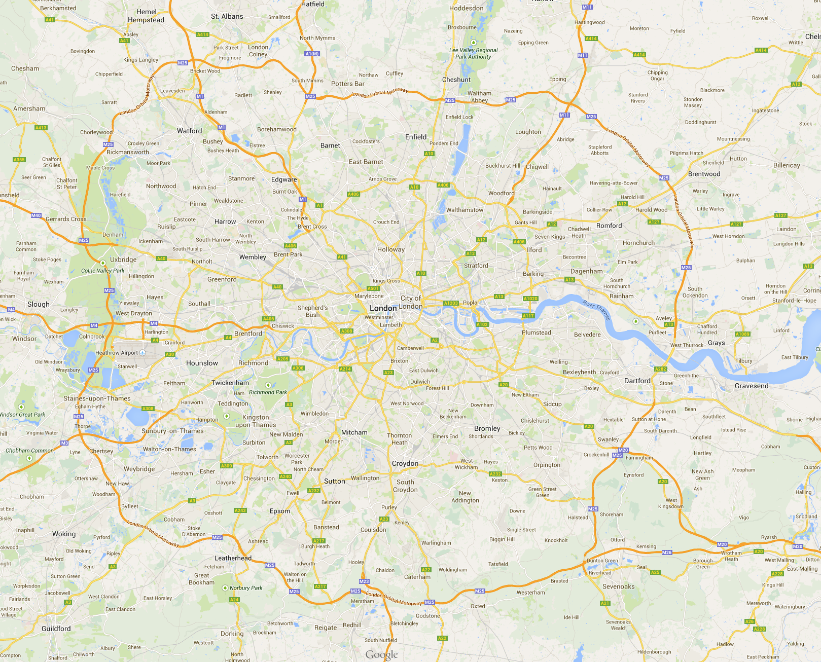
The convergence of these rivers just adds water. The more water, the more people that can live there. This phenomenon of the city has a co-dependency- more water, more people, larger reservoirs, larger industries, larger industries, more city, more city, more people need more water. This phenomenon begins to define traffic in the city with canals and major roads following the flow of water.
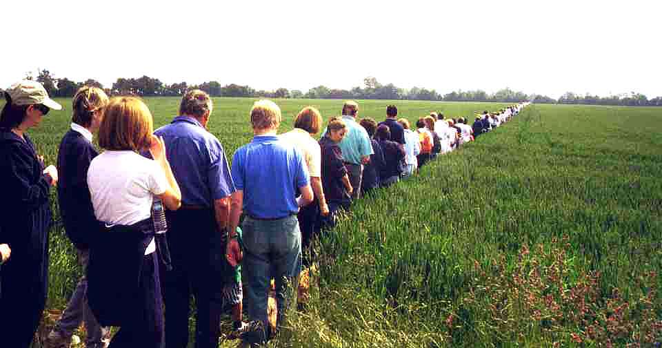
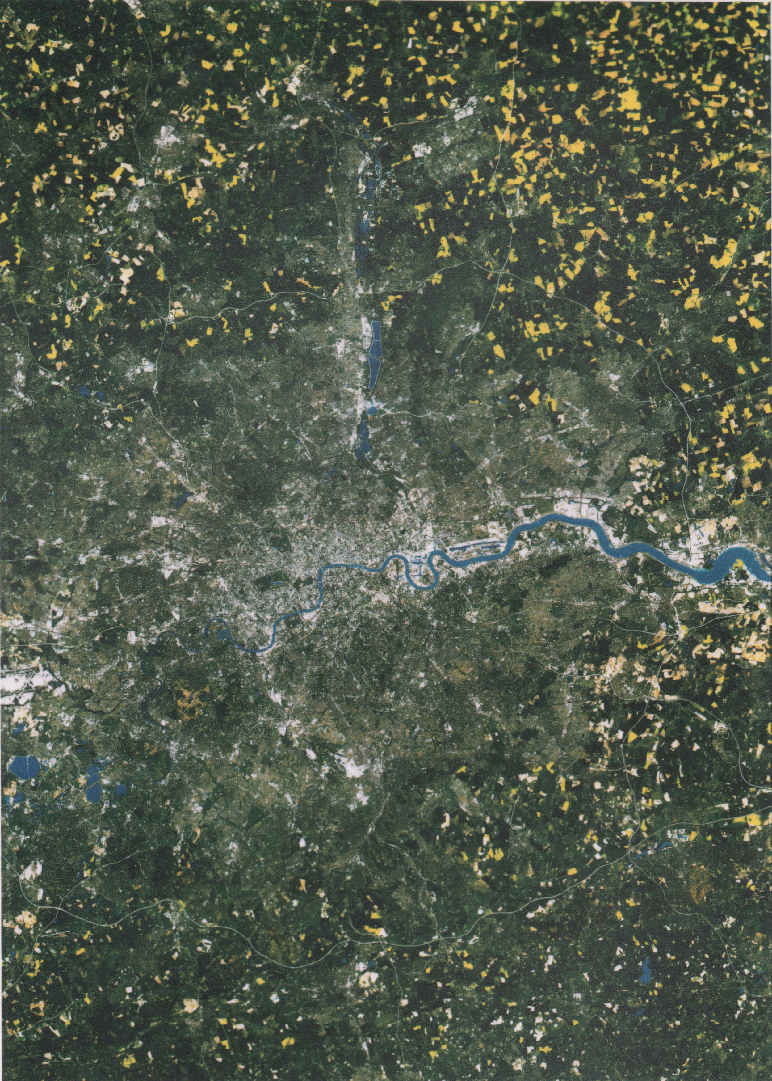
Public footpaths in England have preeminence over many other land uses. If a land owner has purchased a piece of land that has an established public footpath, then the land owner may not erect an obstruction to that public footpath unless an approved method of allowing a foot traveller to surmount that obstacle is constructed in conjunction with that obstacle. That method of surmounting is call a stile. Stiles are common on public footpaths in England. Public footpaths which once traversed the countryside in ancient times are now enshrined in the urban context as pedestrian only walkways that predated the ancient buildings that now conjoin their boundaries.
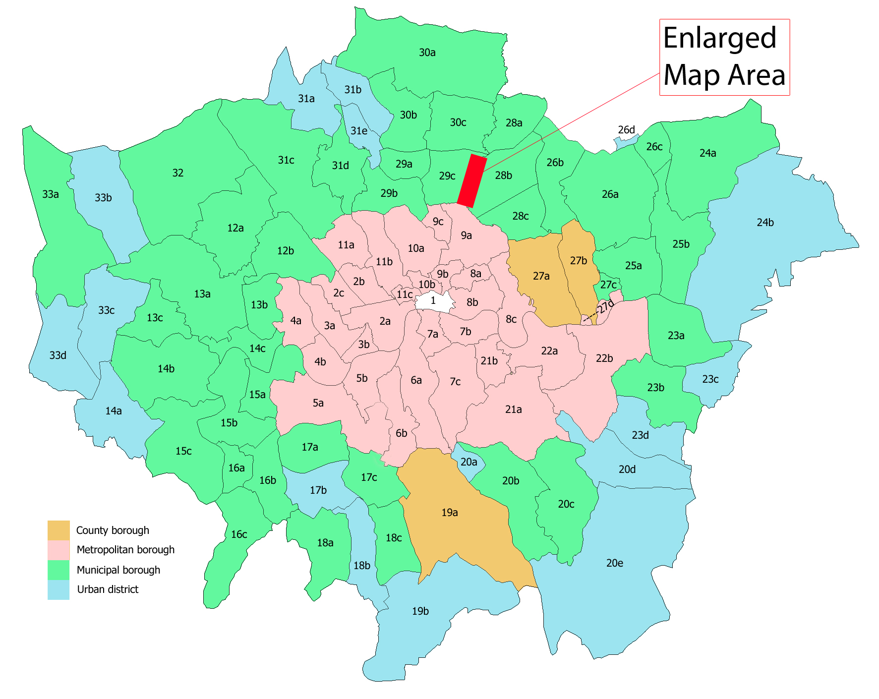
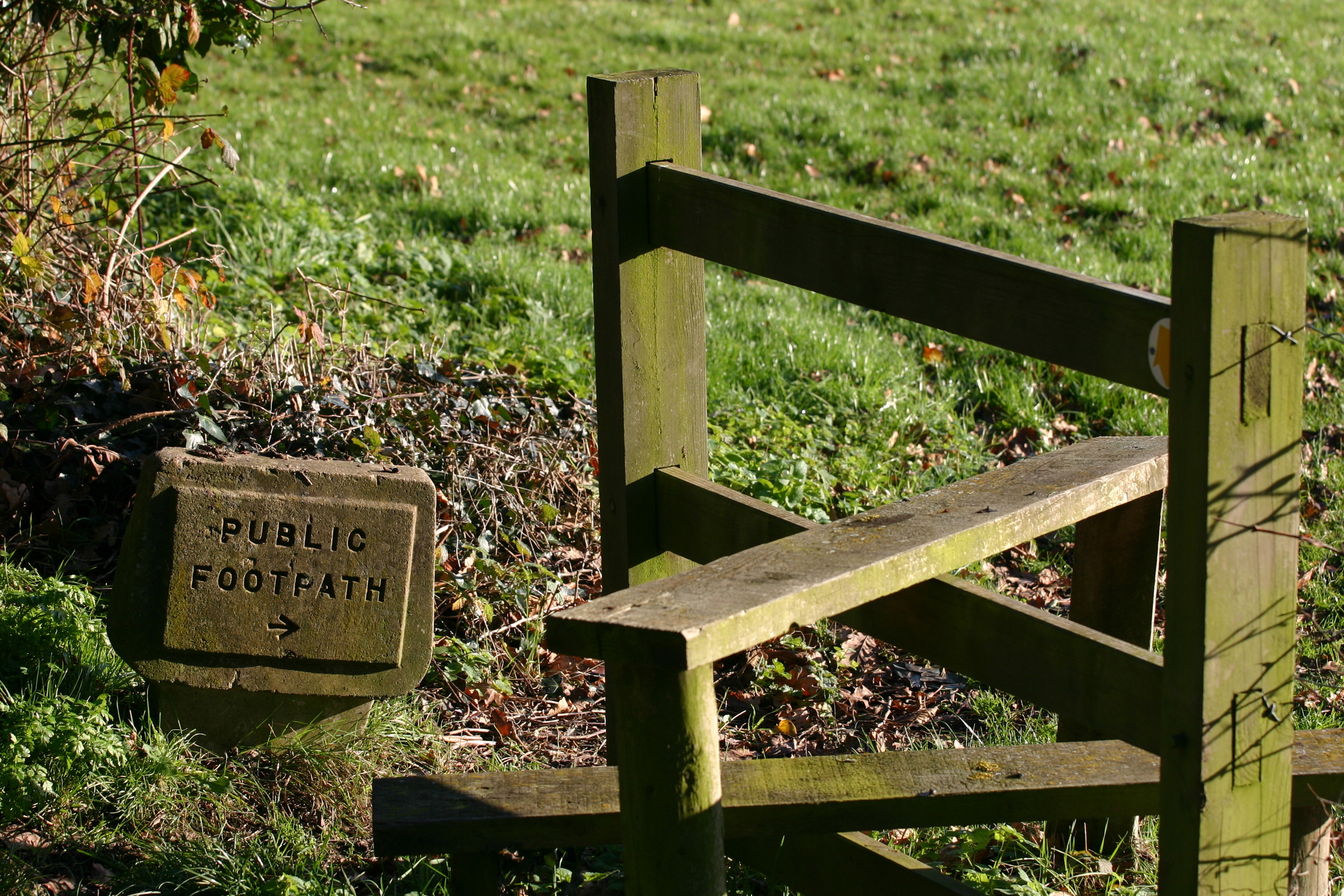
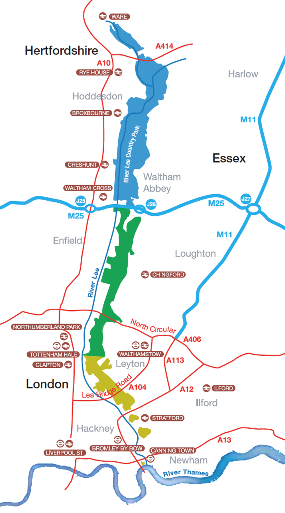
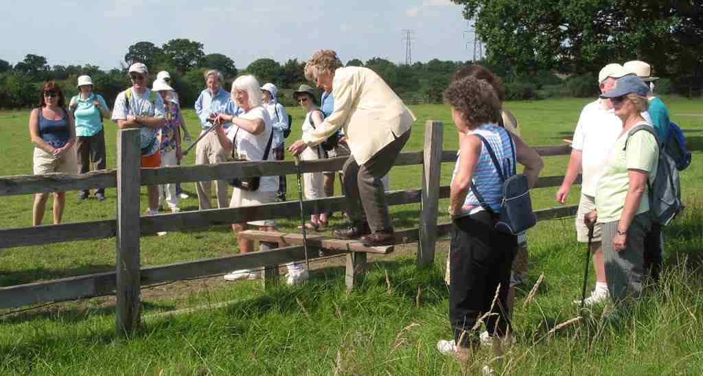
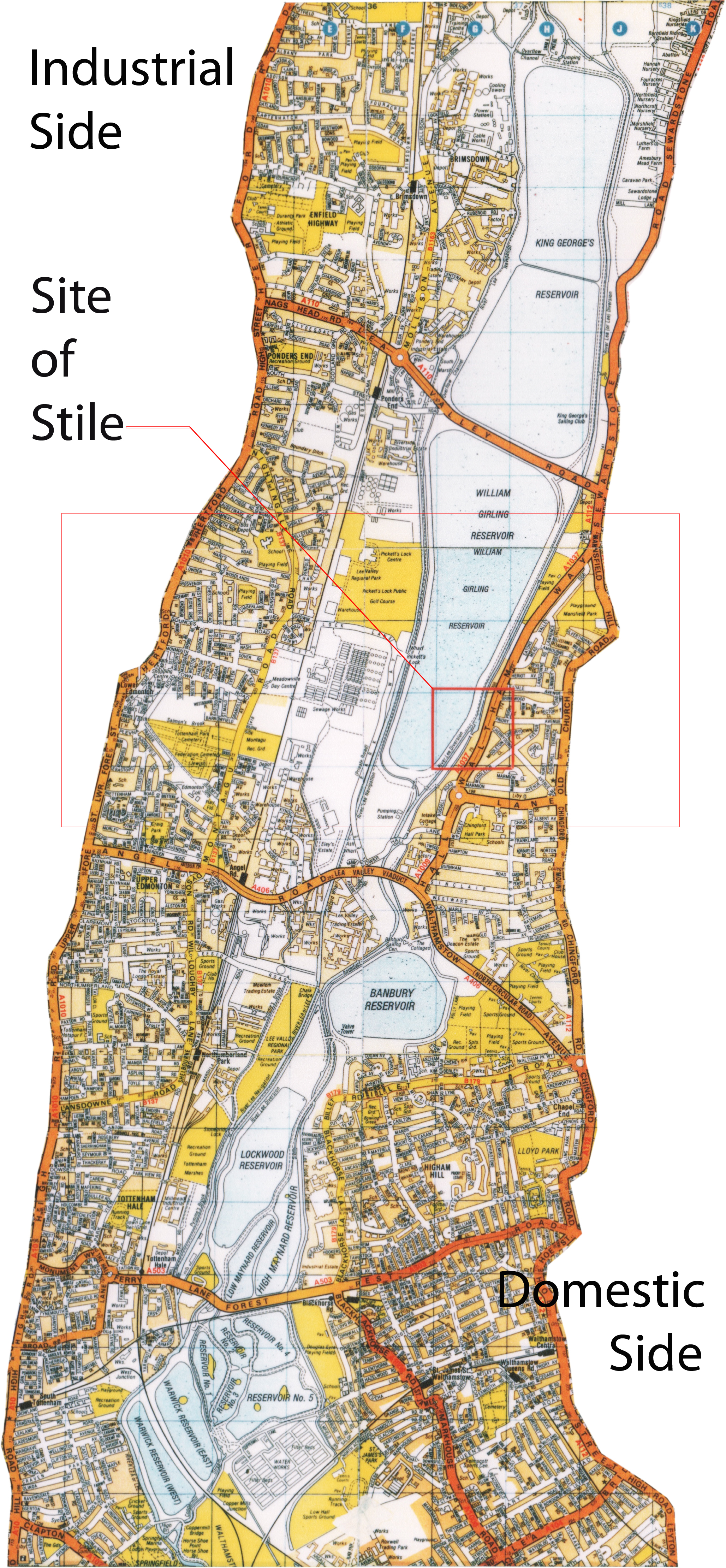
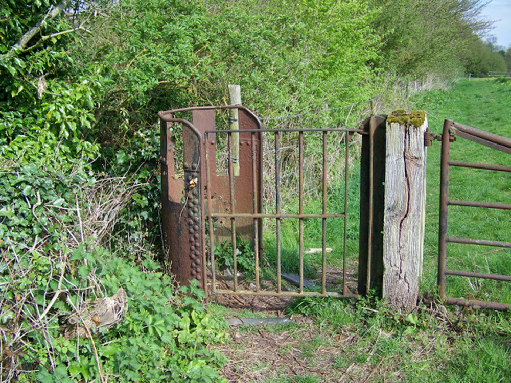

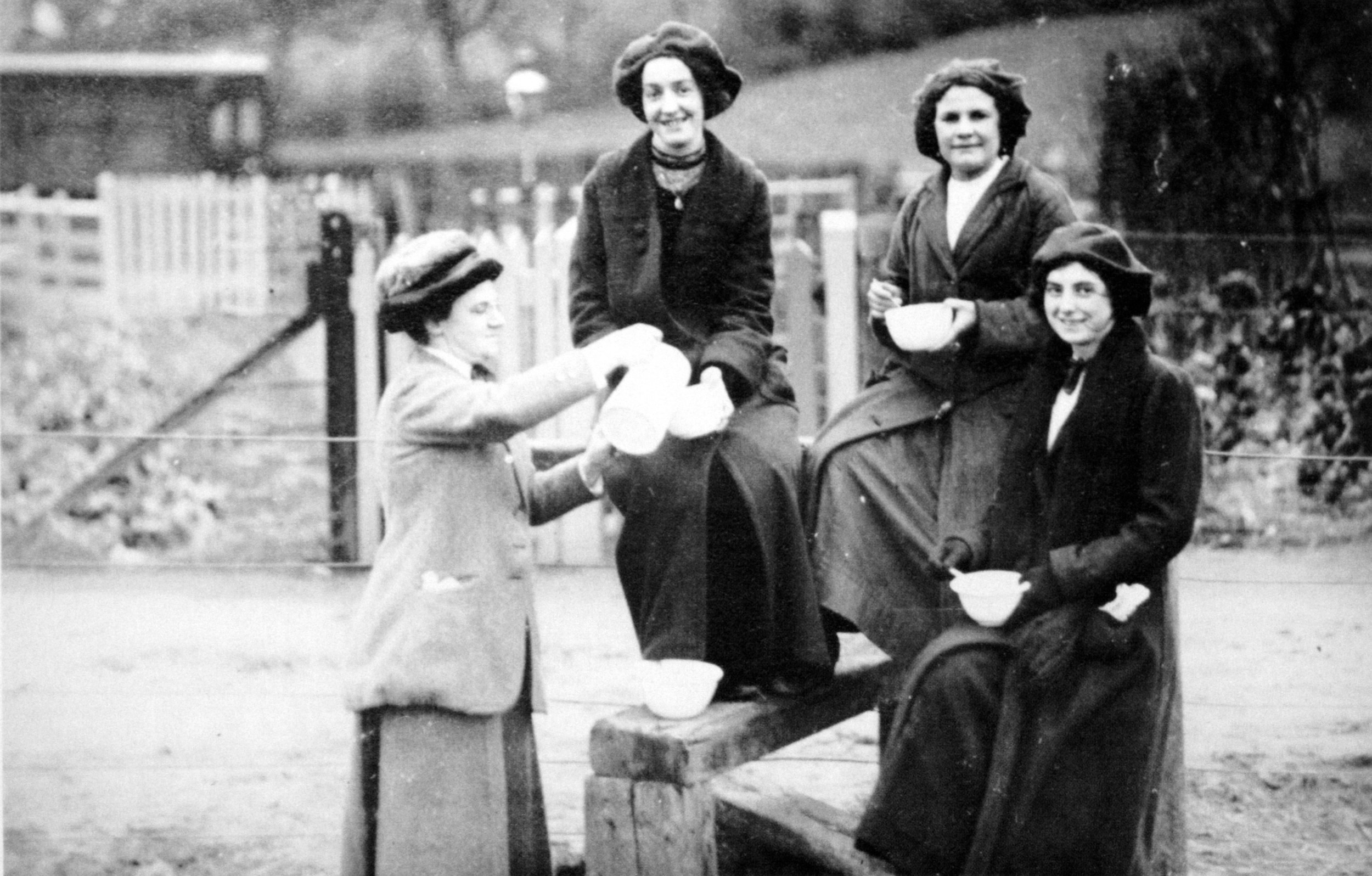

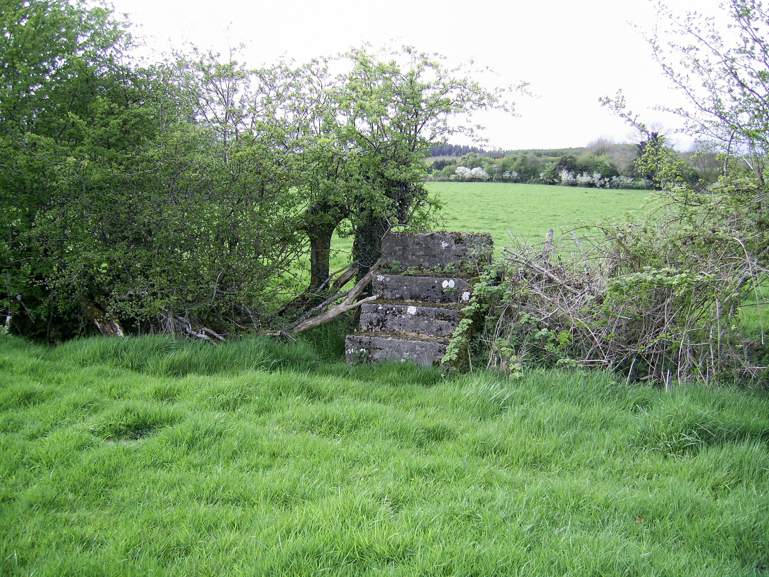
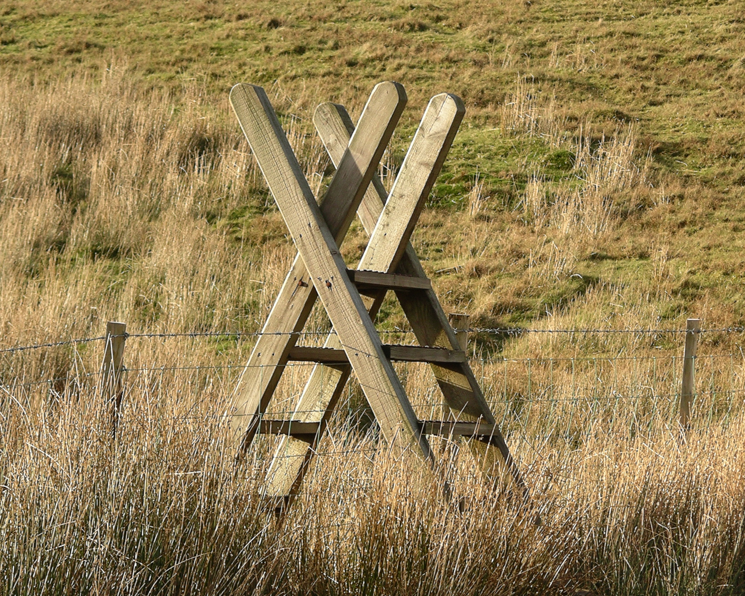
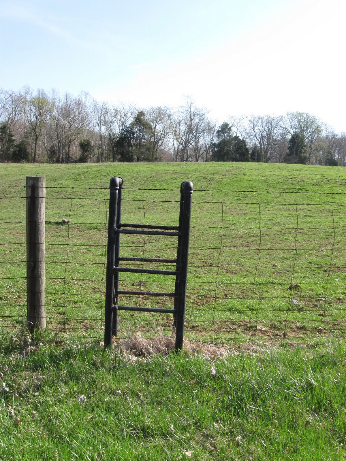
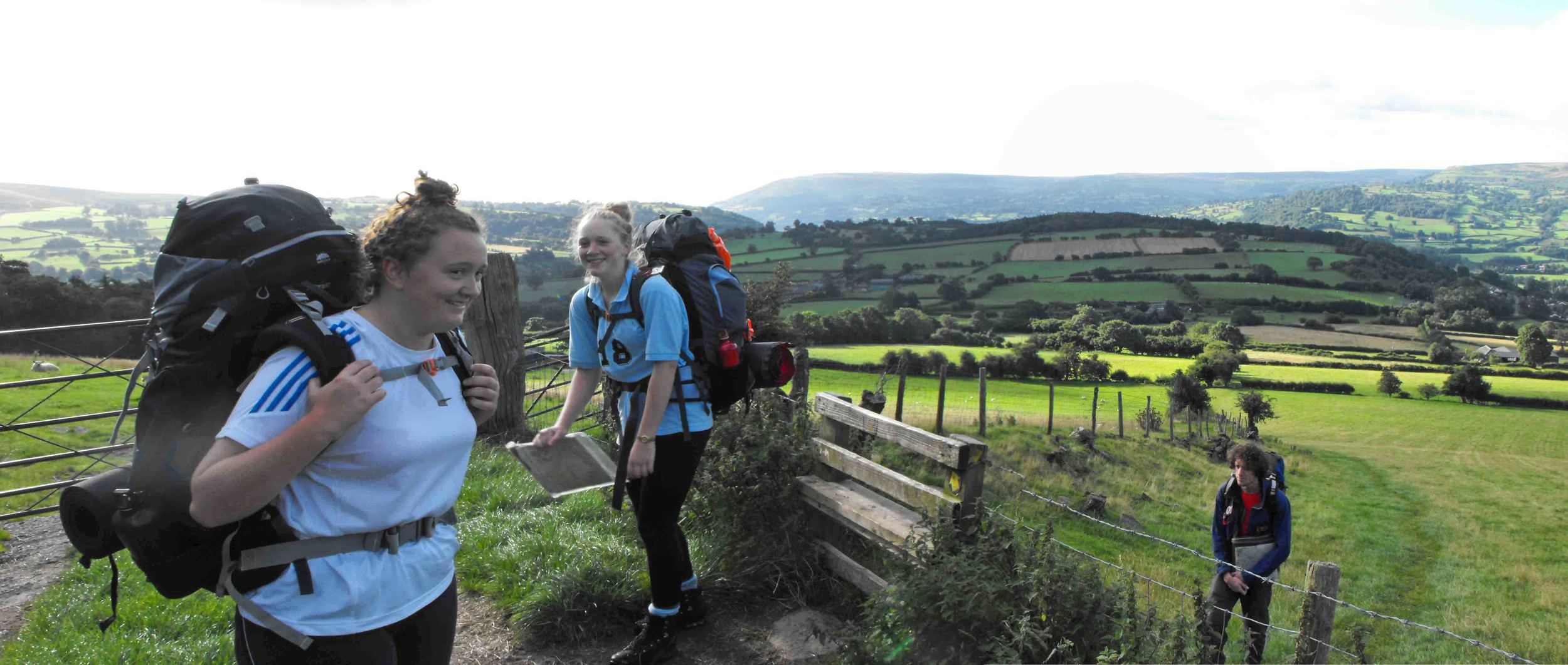
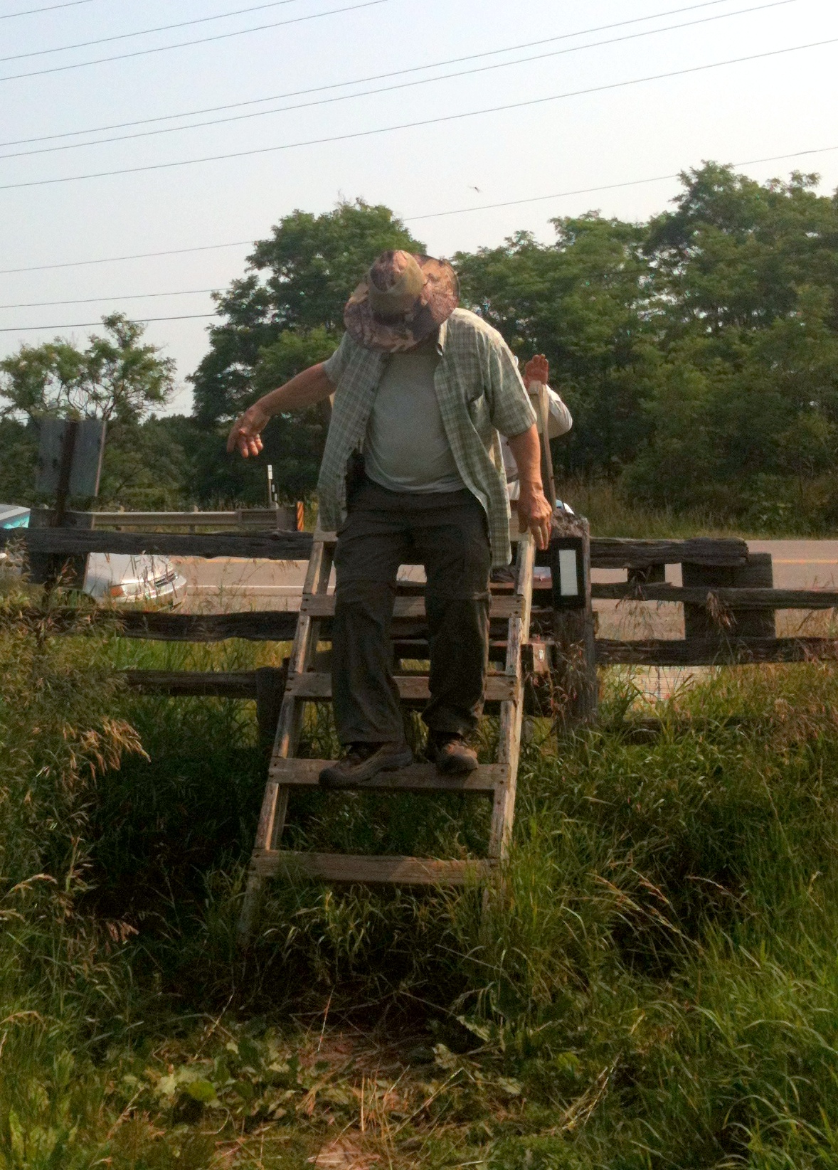
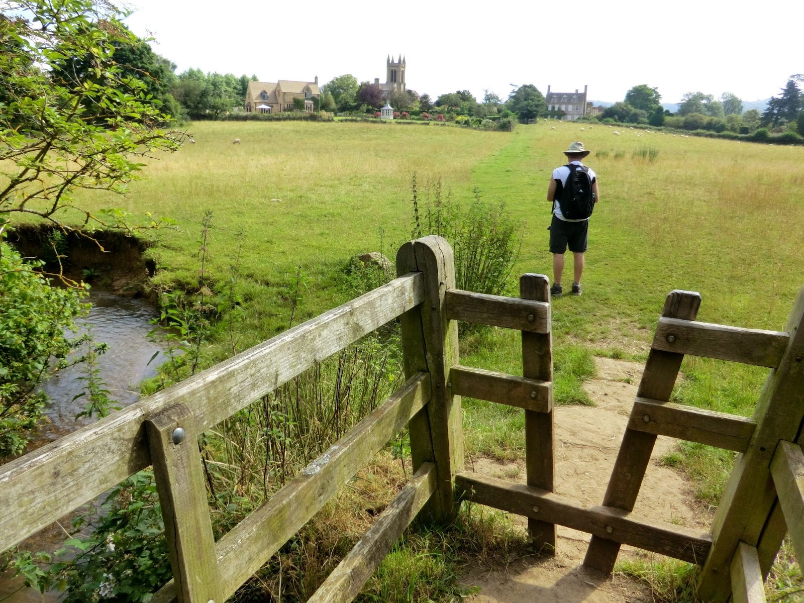
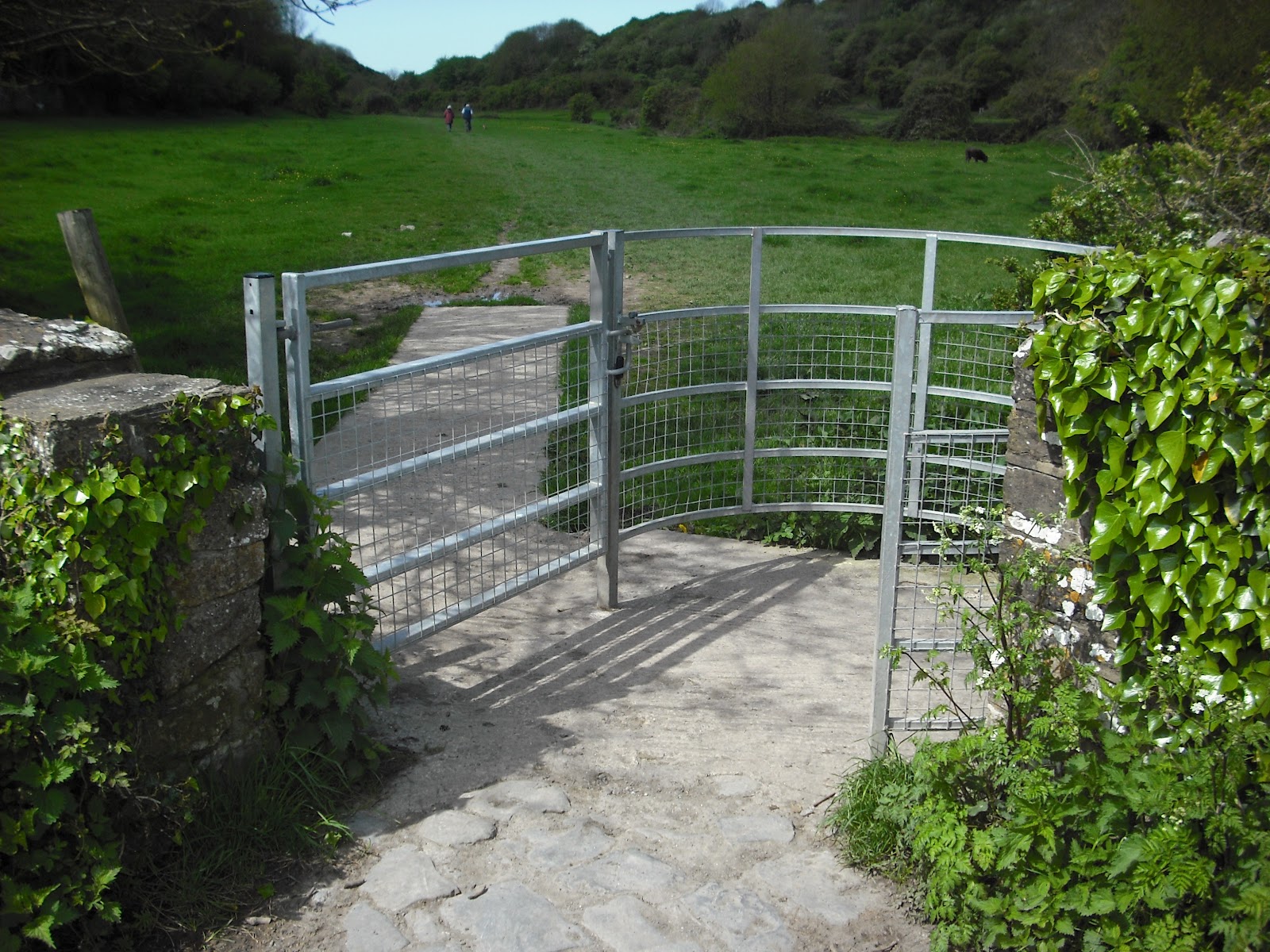
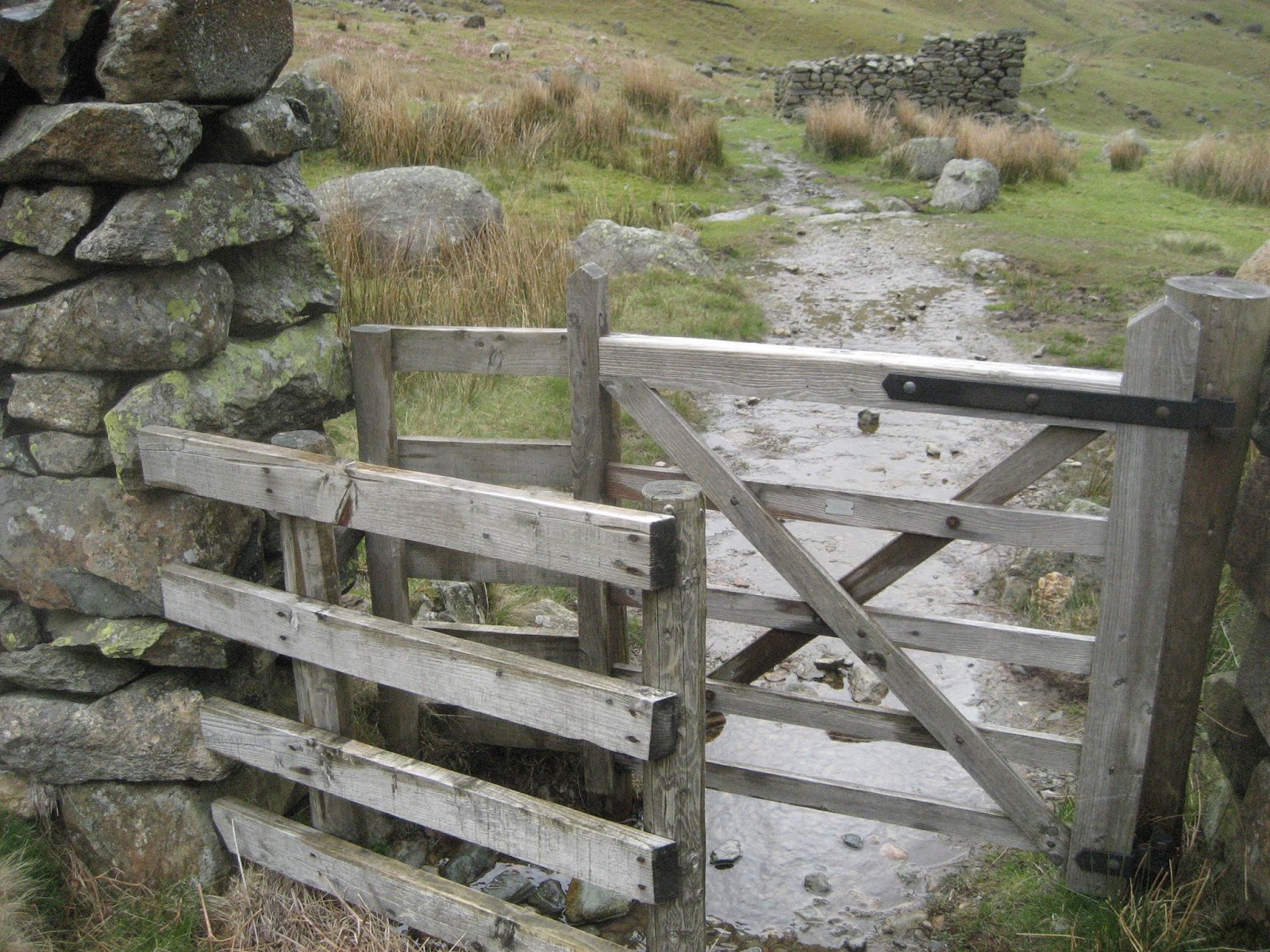
Public Footpath Folly Schematics Industrial/ Suburban Ingredients
The ingredients that go into the design of a stile are selected in this schematic process. The domestic messages of the suburban world shout "Modern Conveniences!" while the utilitarian messages of the industrial world say, "Built to last!". Both worlds are traversed everyday by you and I in our relentless quest to find harmony with the city- this place that dictates where we live and where we work based on ancient geography and the decisions of our fore bearers to settle in this basin, plentiful of water to build with. The water that is available for human consumption in The London Basin was the driver for human settlement of London, a city that celebrated its Millenium in 2012. Water for transportation, water for energy, water for washing, water for drinking, bathing, swimming, cleaning, plumbing, and cooling made London a metropolis. Where there is water, there are public footpaths. The movement of people to the water is the most basic form of human work. The pattern of movement of people from their homes to the city to employ themselves is an extension of activity that follows on from having succeeded in finding and consuming water. After the most basic human need of water has been satisfied, then the other needs, food, then shelter, then money and profit from work all follow on from the primary task of finding water.
This footpath folly is a ladder. When a fence that is constructed for the purpose of containing livestock is erected, and a public footpath encounters that fence, a ladder to traverse that fence is erected called a style. The ladder, or style that traverses the fence that separates the city from the subdivision has a flight that touches down in the residential/ suburban side of the fence. This side of the ladder is comprised of materials/ components that are recognizable as domestic in nature. The flight that touches down on the urban side of the fence is comprised of industrial/ urban materials/ components such as step irons, corrugated metal, checker plate stainless steel and welded fabrication such as "off the shelf" wall papering ladder with plastic friction boots, aluminum handles, ergonomic, spring loaded garage door mechanisms and stowaway attic stairs. The union of these two families of building components are what define the footpath folly so that the meeting of the suburban and the urban can be expressed by touching and stepping and relying on the durability of a bridge between the two worlds with reminders that the nature of each world departed from and each world alighted upon are each registered in the make and model of the very rungs of slip-proof tactile surfaces that are made necessary by the very presence of the edge of the city where there is water.
Given the metaphor of the public footpath, and the elements that define it as discussed above, this bridge between the two worlds would become a technically challenging assembly. The suburban flight and the urban flight each a separate "ladder" would have to be united by an enabling mechanism that would be utilitarian in character, but also whimsically acrobatic and eccentric, creating more curiosity from the joining of the two flights than the sum of the three parts put together- that is because the utilitarian mechanism would not only provide the stability and the durability necessary for the passage of people over the five foot high fence, but the movement necessary for the entire assembly to act like a draw bridge that drew down when in use by people and retracted up when not in use by people so that automobile traffic can pass by the draw bridge which alights upon a communal access drive used by residents whose garages line the single track road which doubles as a footpath.
When the drawbridge is up, automobiles are able to pass by, un hindered by the protrusion of the suburban flight into the travel way because the spring loaded utilitarian platform has retracted the obstacle up into the air, far out of the way, and into the sky. When viewed from afar, the retracted drawbridge is un recognizable as a functional infrastructure, like many draw bridges, when drawn- appear to suspend very recognizable hardware aimlessly up in the air. In order to understand the purpose for this marvel, one has to imagine the objects retracted down to the functional position where they can complete some railway or roadway or even some walkway. So it is with this conjoined marriage of two very odd ladders in the air- the suburban components and the urban, together, in the air, over the driveway, on the fence that separates the city from the suburb. What you see is what you get- no sign explaining the artistic meaning, no plaque defining the purpose of this. When you need to cross the fence on the public footpath you simply pull down on the retracted flight and plant the ladder on the ground, step up to the platform using the wallpapering ladder rungs and slip resistant surfaces with red plastic telescoping segments and avail yourself to the view from the top of the fence.
From here, it is possible to see the water in the sluice gate. This concrete viaduct that redirects the River Lea from its normal course, into the reservoir of drinking water for East London- it lurks invisible from ground level and is only discernible from the slightly elevated position there at the top of the fence approximately five feet higher than normal eye level. Once the suburban flight is retracted back up into the air, it locks into position, forming a durable, checker plate metal bench that allows a canopy to unfurl over your head creating a shelter from the rain and a bird hide to conceal you from above. This industrial strength umbrella is constructed of leaves of corrugated metal that, when manually extended out toward the reservoir beyond- form a shelter from the sun or rain that make it possible to alight upon this bench for a period of time that will enable the observation of the birds that are witnessed by so many bird watchers in this area. Many of the bird watchers traverse this fence to access the bird sanctuaries that separate the reservoir from the city. Now, thanks to the style that has been installed at this well travelled public footpath, they will be able to preview the bird life, camouflaged by the industrial umbrella, perched above the fray and reclined upon a flight out of suburbia that doubles as a bird-hide.
Ready to venture down off of this reclusion in the sky? Simply unlock the industrial flight and it descends down into the new territory with the spring loaded ease of a garage door or a garden gate. The cantilevering springs have been tested to a tension that will leave the 150lb industrial flight (which resembles a skeleton of a manhole) unfolding in graceful equilibrium from its stow position in the sky. Then the step irons that adorn the face of the corrugated sheet metal descend down into the urban side of the fence. The industrial umbrella folds neatly into itself and stacks atop the industrial flight. The step irons also have a slip resistant surface, similar to the rungs on the wallpapering ladder from the suburban flight. These step irons however grip your foot with the tactile pattern of rectangular, cast iron bullets that protrude out of the horse shoe-shaped toe holds and provide traction to your foot that is best experienced with shoes on.
These hot dipped galvanized steel castings are not only shaped like a horse shoe, but they also shine with the zinc glimmer of the galvanized, corrugated sheet metal material that the step irons are captured by. This sheet metal is framed rigid by a ladder of aluminum channel and angle that sandwiches the sheet metal with a sinuous flange that exactly profiles the curving surface of the corrugations. This detail transfers the torque of your foot weight from the step iron into the aluminum channel and locks the sinuous flange into the sheet metal with the stability of a masonry detail that the step iron was designed for. The top flange continues through the rectangular opening in the sheet metal and top loads the corrugation cut in plan. This is a very strong edge with which to place the step iron which is through bolted through the top flange of the channel in bolt locations that are coordinated with the undulations of sheet metal under the flange. The stainless hardware that through bolts the step iron to the aluminum channel is chunky enough to blend in with the shiny, tactile surface of the step iron and yet finished looking enough also work with the sheet metal. The common finish being the zinc component of the galvanized sheet metal and the hot dipped step iron unify the finish aesthetically and for durability.
Descend down the step irons and find yourself between the precast concrete fence panels and the shiny galvanized family of components that make up the industrial flight. This space, unlike the suburban side of the draw bridge, has the tough, hardened and industrial feel of the world that characterizes this side of the fence. Exit to the side of the industrial flight and the spring loaded mechanism is ready to stow the industrial flight up into the sky from where it came. Simply lift the assembly with a single hand and it will respond by collapsing upwards until it is locked in position, ready for the next foot traveller to deploy the mechanism. As the industrial flight rejoins the suburban flight in a locked embrace above the fence, they become indistinguishable as before, the apparent collision of two worlds- expressed in terms of the familiar objects and obstacles that we encounter in everyday life. Walk away on the public footpath toward the territory of the city, away from the territory of the suburb, and remember that this transition from one to the other was framed by folly.
Why? The technical studies program at the AA offers students the opportunity to solve for their requirements to achieve a technical understanding by building a fragment of a building, or some derivation of a building design by building a touchstone that mimics the meme of the building in some playful way. This touchstone is one such meme. The project that is the basis of the meme is the Bromley Beekeeper's Institute where the same urban edge, the same materials and the same utilitarian/ urban theme is played off of the suburban and the domestic. The net result of these more targeted technical studies is to integrate the culture of the project design into the technical execution creating continuity of design rather than requiring the student to perform some cut and dried technical requirement that is divorced from the design work. This approach is common at architectural schools where the emphasis is on the technical prowess, on computer aided design and upon drafting symbology is prioritized leaving the student with a fragmented view of design as something that some one upstairs adds to the building with a flick of the wrist. Ultimately, this characterizes the material world in the present culture. Prior generations had a more unified view of technical execution and design such as the craftsmen of the colonial era and the Shakers, who preserved the colonial sensibilities and rejected the expedience of the assembly line and rejected the pretense of design that we saw throughout the 1980s.
The footpath folly also explores the profundity of the style phenom. These "bridges over fences" are best experienced as a simple series of steps over an obstacle rather than the "overblown drawbridge" that the folly celebrates with mischief, guile and conspicuous consumption of cast iron and steel in order to demonstrate good welds, bolted connections and coherence of assembly for technical consideration and a strong sense of the well made object. The folly was also an opportunity to err and to overstep. As an academic project, constructed in the workshop on the premises of the school, it was also that- a clearly orangutanian effort partly a welding lesson and partly a lesson in hand made steel assembly without the use of computers, printers, operating systems, digitizers or other pointing devices. Here, the shop drawings were ink drawn by hand using, in some cases- as built information that preceded the drawings. The utilitarian mechanism was welded with a great deal of help from the teacher's assistant in the shop. The structural calculations that determined the height of the spring load were research and calculated by John Millard and constructed to those specifications, assembled and demonstrated to work. These achievements are not possible on a multiple choice examination where your GPA is you calling card. The freedom that a student of architecture has at the AA School in London is a rare commodity that once enjoyed, is a manner to be accustomed to, and not to be taken away. It is, of course inevitable that such freedom is revoked immediately upon being seated in your cubicle at your first job out of school- what the AA hopes to instill in a student is the power that control of the pencil has over the project. Every opportunity to design rigor into a project is therefore taken, damn the torpedoes.


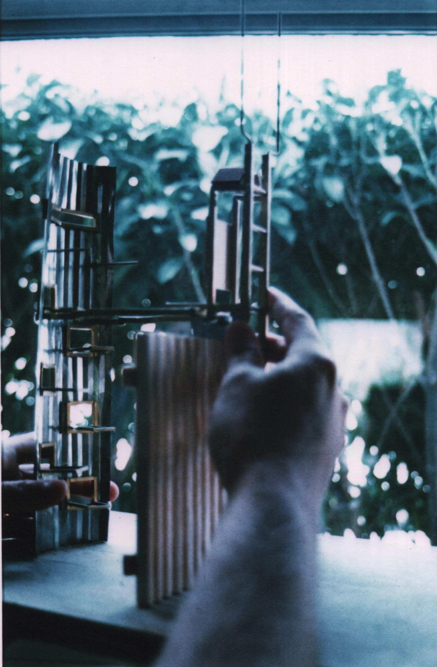


CONSTRUCTION OF A FOLLY FOR A FENCE- A PEDESTRIAN DRAWBRIDGE
The ingredients that go into the design of a stile are selected in this schematic process. The domestic messages of the suburban world shout "Modern Conveniences!" while the utilitarian messages of the industrial world say, "Built to last!". Both worlds are traversed everyday by you and I in our relentless quest to find harmony with the city- this place that dictates where we live and where we work based on ancient geography and the decisions of our fore bearers to settle in this basin, plentiful of water to build with. The water that is available for human consumption in The London Basin was the driver for human settlement of London, a city that celebrated its Millenium in 2012. Water for transportation, water for energy, water for washing, water for drinking, bathing, swimming, cleaning, plumbing, and cooling made London a metropolis. Where there is water, there are public footpaths. The movement of people to the water is the most basic form of human work. The pattern of movement of people from their homes to the city to employ themselves is an extension of activity that follows on from having succeeded in finding and consuming water. After the most basic human need of water has been satisfied, then the other needs, food, then shelter, then money and profit from work all follow on from the primary task of finding water.
This footpath folly is a ladder. When a fence that is constructed for the purpose of containing livestock is erected, and a public footpath encounters that fence, a ladder to traverse that fence is erected called a style. The ladder, or style that traverses the fence that separates the city from the subdivision has a flight that touches down in the residential/ suburban side of the fence. This side of the ladder is comprised of materials/ components that are recognizable as domestic in nature. The flight that touches down on the urban side of the fence is comprised of industrial/ urban materials/ components such as step irons, corrugated metal, checker plate stainless steel and welded fabrication such as "off the shelf" wall papering ladder with plastic friction boots, aluminum handles, ergonomic, spring loaded garage door mechanisms and stowaway attic stairs. The union of these two families of building components are what define the footpath folly so that the meeting of the suburban and the urban can be expressed by touching and stepping and relying on the durability of a bridge between the two worlds with reminders that the nature of each world departed from and each world alighted upon are each registered in the make and model of the very rungs of slip-proof tactile surfaces that are made necessary by the very presence of the edge of the city where there is water.
Given the metaphor of the public footpath, and the elements that define it as discussed above, this bridge between the two worlds would become a technically challenging assembly. The suburban flight and the urban flight each a separate "ladder" would have to be united by an enabling mechanism that would be utilitarian in character, but also whimsically acrobatic and eccentric, creating more curiosity from the joining of the two flights than the sum of the three parts put together- that is because the utilitarian mechanism would not only provide the stability and the durability necessary for the passage of people over the five foot high fence, but the movement necessary for the entire assembly to act like a draw bridge that drew down when in use by people and retracted up when not in use by people so that automobile traffic can pass by the draw bridge which alights upon a communal access drive used by residents whose garages line the single track road which doubles as a footpath.
When the drawbridge is up, automobiles are able to pass by, un hindered by the protrusion of the suburban flight into the travel way because the spring loaded utilitarian platform has retracted the obstacle up into the air, far out of the way, and into the sky. When viewed from afar, the retracted drawbridge is un recognizable as a functional infrastructure, like many draw bridges, when drawn- appear to suspend very recognizable hardware aimlessly up in the air. In order to understand the purpose for this marvel, one has to imagine the objects retracted down to the functional position where they can complete some railway or roadway or even some walkway. So it is with this conjoined marriage of two very odd ladders in the air- the suburban components and the urban, together, in the air, over the driveway, on the fence that separates the city from the suburb. What you see is what you get- no sign explaining the artistic meaning, no plaque defining the purpose of this. When you need to cross the fence on the public footpath you simply pull down on the retracted flight and plant the ladder on the ground, step up to the platform using the wallpapering ladder rungs and slip resistant surfaces with red plastic telescoping segments and avail yourself to the view from the top of the fence.
From here, it is possible to see the water in the sluice gate. This concrete viaduct that redirects the River Lea from its normal course, into the reservoir of drinking water for East London- it lurks invisible from ground level and is only discernible from the slightly elevated position there at the top of the fence approximately five feet higher than normal eye level. Once the suburban flight is retracted back up into the air, it locks into position, forming a durable, checker plate metal bench that allows a canopy to unfurl over your head creating a shelter from the rain and a bird hide to conceal you from above. This industrial strength umbrella is constructed of leaves of corrugated metal that, when manually extended out toward the reservoir beyond- form a shelter from the sun or rain that make it possible to alight upon this bench for a period of time that will enable the observation of the birds that are witnessed by so many bird watchers in this area. Many of the bird watchers traverse this fence to access the bird sanctuaries that separate the reservoir from the city. Now, thanks to the style that has been installed at this well travelled public footpath, they will be able to preview the bird life, camouflaged by the industrial umbrella, perched above the fray and reclined upon a flight out of suburbia that doubles as a bird-hide.
Ready to venture down off of this reclusion in the sky? Simply unlock the industrial flight and it descends down into the new territory with the spring loaded ease of a garage door or a garden gate. The cantilevering springs have been tested to a tension that will leave the 150lb industrial flight (which resembles a skeleton of a manhole) unfolding in graceful equilibrium from its stow position in the sky. Then the step irons that adorn the face of the corrugated sheet metal descend down into the urban side of the fence. The industrial umbrella folds neatly into itself and stacks atop the industrial flight. The step irons also have a slip resistant surface, similar to the rungs on the wallpapering ladder from the suburban flight. These step irons however grip your foot with the tactile pattern of rectangular, cast iron bullets that protrude out of the horse shoe-shaped toe holds and provide traction to your foot that is best experienced with shoes on.
These hot dipped galvanized steel castings are not only shaped like a horse shoe, but they also shine with the zinc glimmer of the galvanized, corrugated sheet metal material that the step irons are captured by. This sheet metal is framed rigid by a ladder of aluminum channel and angle that sandwiches the sheet metal with a sinuous flange that exactly profiles the curving surface of the corrugations. This detail transfers the torque of your foot weight from the step iron into the aluminum channel and locks the sinuous flange into the sheet metal with the stability of a masonry detail that the step iron was designed for. The top flange continues through the rectangular opening in the sheet metal and top loads the corrugation cut in plan. This is a very strong edge with which to place the step iron which is through bolted through the top flange of the channel in bolt locations that are coordinated with the undulations of sheet metal under the flange. The stainless hardware that through bolts the step iron to the aluminum channel is chunky enough to blend in with the shiny, tactile surface of the step iron and yet finished looking enough also work with the sheet metal. The common finish being the zinc component of the galvanized sheet metal and the hot dipped step iron unify the finish aesthetically and for durability.
Descend down the step irons and find yourself between the precast concrete fence panels and the shiny galvanized family of components that make up the industrial flight. This space, unlike the suburban side of the draw bridge, has the tough, hardened and industrial feel of the world that characterizes this side of the fence. Exit to the side of the industrial flight and the spring loaded mechanism is ready to stow the industrial flight up into the sky from where it came. Simply lift the assembly with a single hand and it will respond by collapsing upwards until it is locked in position, ready for the next foot traveller to deploy the mechanism. As the industrial flight rejoins the suburban flight in a locked embrace above the fence, they become indistinguishable as before, the apparent collision of two worlds- expressed in terms of the familiar objects and obstacles that we encounter in everyday life. Walk away on the public footpath toward the territory of the city, away from the territory of the suburb, and remember that this transition from one to the other was framed by folly.
Why? The technical studies program at the AA offers students the opportunity to solve for their requirements to achieve a technical understanding by building a fragment of a building, or some derivation of a building design by building a touchstone that mimics the meme of the building in some playful way. This touchstone is one such meme. The project that is the basis of the meme is the Bromley Beekeeper's Institute where the same urban edge, the same materials and the same utilitarian/ urban theme is played off of the suburban and the domestic. The net result of these more targeted technical studies is to integrate the culture of the project design into the technical execution creating continuity of design rather than requiring the student to perform some cut and dried technical requirement that is divorced from the design work. This approach is common at architectural schools where the emphasis is on the technical prowess, on computer aided design and upon drafting symbology is prioritized leaving the student with a fragmented view of design as something that some one upstairs adds to the building with a flick of the wrist. Ultimately, this characterizes the material world in the present culture. Prior generations had a more unified view of technical execution and design such as the craftsmen of the colonial era and the Shakers, who preserved the colonial sensibilities and rejected the expedience of the assembly line and rejected the pretense of design that we saw throughout the 1980s.
The footpath folly also explores the profundity of the style phenom. These "bridges over fences" are best experienced as a simple series of steps over an obstacle rather than the "overblown drawbridge" that the folly celebrates with mischief, guile and conspicuous consumption of cast iron and steel in order to demonstrate good welds, bolted connections and coherence of assembly for technical consideration and a strong sense of the well made object. The folly was also an opportunity to err and to overstep. As an academic project, constructed in the workshop on the premises of the school, it was also that- a clearly orangutanian effort partly a welding lesson and partly a lesson in hand made steel assembly without the use of computers, printers, operating systems, digitizers or other pointing devices. Here, the shop drawings were ink drawn by hand using, in some cases- as built information that preceded the drawings. The utilitarian mechanism was welded with a great deal of help from the teacher's assistant in the shop. The structural calculations that determined the height of the spring load were research and calculated by John Millard and constructed to those specifications, assembled and demonstrated to work. These achievements are not possible on a multiple choice examination where your GPA is you calling card. The freedom that a student of architecture has at the AA School in London is a rare commodity that once enjoyed, is a manner to be accustomed to, and not to be taken away. It is, of course inevitable that such freedom is revoked immediately upon being seated in your cubicle at your first job out of school- what the AA hopes to instill in a student is the power that control of the pencil has over the project. Every opportunity to design rigor into a project is therefore taken, damn the torpedoes.


RENOVATION, DEMOLITION AND RECONSTRUCTION OF CENTERPOINT
Project Summary: CentrePoint Tower, built in 1971 in Central London is the subject of an assignment by Intermediate Unit 8 of The Architectural Association School of Architecture. The assignment calls for the "remodeling" or "renovation" of the tower into a new landmark that is befitting of the bustling entertainment district that The West End of London has come to be known for. The students in Unit 8 embraced many outrageous concepts, including re skinning the tower with an aluminum cylinder detailed to look exactly like an enormous Coca-Cola Can. The proposal discussed below is a replacement tower- for the original demolished CentrePoint Tower, a re planning of the traffic system and the weather system surrounding the new tower- redesigned after a process of attempting a renovation using fragments of The Queen Mary. The replacement tower design evolved out of rigorous testing of the aerodynamic properties of the replacement. The new building will produce a significant amount of its own electricity from wind baffles that correct the flow of wind from crashing down on cowering tube travelers. These baffles redirect the wind upwards by altering the air pressure at ground level and inducing laminar updraft using the Bernoulli Effect in some 18 Giant Wind Baffles detailed to belong to the family of wind sculpture by Susumu Shingu. The new tower shape, evolved after a dozen wind tunnel tests on differently shaped scale models including a final test at Kingston Polytechnic with Rolls Royce aeronautical engineer William Ross. The West End of London- redefined by a new landmark that employs the sun and the wind to derive its shape, orientation and golden panache.
AA Tutors: Peter Salter, Pascal Schoning, Warren Chalk.
Structural Engineer: Mark Whitby of Whitby and Byrd.
Aeronautical Engineer: Brian Gould of Kingston Polytechnic College of Aerospace Engineering
Aeronautical Engineer: William Ross of Rolls Royce
Work submitted for RIBA Certification: RIBA Part 1 (High Pass)
Date: July 1987
After exploring a steel intervention to the existing tower using fragments of the Queen Mary, and having those drawings displayed prominantly bu my tutor in "The Projects Review", the Architectural Association's yearbook of student projects, my tutors encouraged me to press on with the demolition and redesign of a new replacement tower at the end of my first year in the school.
The new tower would also act as a landmark for the West End of London as the existing tower does. The difference the new tower would bring to the West End would be the weather, alterations to many aspects of the microclimate of St. Giles Circus where the tower would redefine all aspects of travel through this gateway to the West End.
The New Centre Point Tower would defeat significant wind shear that is created by the existing tower. Life in the currently windswept plaza beneath the southwest facade and the circus generally would be ameliorated by a re-oriented, re-shaped, and re-invented tower that manipulates the prevailing south western wind using aeronautical engineering.
Two Aeronautical Engineers named Brian Gould and Willie Ross took an interest in the project and devised a method of testing 1:500 solid wood models in a wind tunnel using unspun wool tethered onto fuse wire. Following their method of attaching these "tell tails" to the sw facade of the various wood model shapes, over 12 different tower shapes were tested in a wind tunnel and mapped for turbulence using long exposure photography. "Tell tails" that moved due to turbulence were out of focus and stationary tell tails were in laminar flowing air and would be in focus. This way, I could map the movement of air across the SW facade and modify the building shape until up-draft was achieved, reversing the current phenomenon of 60 mile per hour winds crashing down onto pedestrians in the plaza below. In addition to the reduced air speed at ground level, temperatures also would stablize to ambient urban ground level temperatures where previously higher altitude cool air forced to the ground by wind shear created lower temperatures.
Several building shapes were modeled through this process, which was led by the aeronautical engineers from Kingston Polytechnic and Rolls Royce. The shape that resulted from this process of wind testing was a tapering, twisting shape that gathered low altitude air and channelled is upwards and around the south edge of the building shape. The effect of this building shape, which tapered and twisted like a plant rising to reorient itself into the sun became the compelling volume for which a structural strategy was conceived and developed with Mark Whitby of Whitby and Byrd Structural Engineers. The resulting building shape also required a modification to the degree of tapering in order to address urban planning issues at the intersection of Tottenham Court Road and Oxford Street. This correction to the tapering shape resulted in the addition of a scaffold of aerodynamic spoilers at ground level to enhance the updraft effect. These spoilers were modeled at a scale of 1:100 (five times larger than the initial massing models) on a 1:100 scale model of the desired building shape which was constructed of shim steel, brass angle, polycarbonate floor shapes and monofilament wire w/ polythene to simulate viscous glass facade with wind bracing. The fully assembled 1:100 scale model was placed in a wind tunnel at Kingston Polytechnic and rigged with scaled up tell tails that achieved similar updraft results as the original building shape at 1:500.

...by Richard Seifert Architects in Central London- This tower became the subject of study by The Architectural Association School of Architecture Intermediate Unit 8 in 1984. The objective of the study was "make it better" by proposing renovation, additions, reskinning, remaking and downright demolishing the empty, relentless pile of precast masonry.

...I was the only student to propose a replacement for the existing Counterpoint Tower. This decision was not made lightly and was an interactive process that started with a "renovation" using fragments of R.M.S. Queen Mary I. After completing a number of anti-rational "additions" and "renovations" using The Queen Mary- the decision to demolish the tower was made in consultation with my tutors and the structural and aeronautical engineers who were co-opted into service on this long term project which spanned from 1984 to 1987.

Q: What are those Susumu Shingu structures doing at the base of your building?
A: These are architectural fabric spoilers that induce the prevailing SW wind into an "updraft" across the SW facade where the current Centrepoint tower induces "downdraft". This updraft was observable in wind tunnel testing at Kingston University. The spoilers cause the air pressure at the lower levels of the building to significantly decrease due to micro-turbulence induced by the Bernoulli Effect as wind enters the orifice of each spoiler and expands from laminar flow to turbulent flow creating a funnel shaped cloud of turbulence that guides laminar flowing wind upwards.

The opportunity to build a 1:100 model of the proposal after three years of progressing this design with my tutors and my pro-bono structural, and aeronautical engineering consultants was a great privilege, particularly as one of the aeronautical engineers took a keen interest in constructing the model and assuring himself that the spoilers would be modeled to scale.

After testing several smaller scale models at 1:500 that determined the shape and contour of the tower, the larger scale model was built at 1:100. Aeronautical engineers counseled that it would produce observable results to repeatedly test the smaller models using long exposure photography while under "wind" load using a hair dryer and un-spun wool tell tails hinged and pinned to each balsa model facade. The tell tails that were in focus despite the long exposure were in laminar flowing wind, the direction of which could be determined by the disposition of the tell-tail in the photo. The tell-tails that were out of focus due to movement from turbulence proved that there was no discernible wind direction (and hence no up-draft). By using this method, wind charts were made for each model resulting in a prototype for the larger model. Upon selection of this prototype, the base was determined to be too wide and my tutor drove a last minute adjustment to the width of the model. This upset the updraft flow when re-tested using the hair dryer and the tell-tails. Aeronautical Engineers introduced the spoilers to improve the creation of a vortex at the base, despite the reduction in width. Testing of the spoilers on the 1:100 scale model was possible using cladding for the model using monofilament fishing wire with polythene sheeting woven between the monofilament cables. The photo above is a still (reversed) from a vhs video take during the wind tunnel test which proved successful use of the spoilers since updraft was measurable on the 1:100 scale model.

The masts which support these spoilers tie into the primary building structure through gasket spandrel panels with the ability to accommodate movement from the pneumatic rams. These rams constrain the rotation of the spoiler to a 30 degree rotation and prevent them from slamming around. The primary structure of the building's shear walls is a bi-directional sandwich of cortex steel sheet pile filled with concrete. The shear walls change shape as the altitude of the structure increases, loading requirements change and the convex base of the envelope morphs into a compound curving/ concave shape determined by the ever changing glazing surface.

Transfer Floors occur every 20m and tie the continuously rising shear walls into the concrete diaphragm that interrupts the wind bracing of the glazing system. The repetition of these transfer floors allows for MEP Distribution to occur locally creating 20m vertical zones. The horizontal Lines shown in the section represent the horizontal sheet pile that will serve as loading points for future buildout of the tenant improvements.

Egress from the tube allows a pedestrian to surface inside the air conditioned space of the semi public "great hall" that is formed by the over-arching structure formed from rusting core-ten steel sheet pile, sandwiched together to form a fireproof core of concrete encased in corrugated steel. These ledges formed by the horizontal sheet pile create loading point for tenant improvements where transfer floors every 20m up are the only constraint to volume. The shell and core of the building are determined in this proposal with the building's fit out the subject of a future intervention.

The horizontal slabs of space are regular and stiffened by elevator cores at opposing ends of the floor plan. This volume of space has proved to be unpopular with the leasing community due to the fact that there was very little flexibility to grow or modify use within the space. For this reason, the existing tower has been empty for several years and the building provides a landmark in the West End (and very little else).

In breaking students of conventional architectural baggage, The Architectural Association School of Architecture often required students to pursue anti-rational drawings in order to convey an embarkation from the forced reality, expediency, pre-requisitism and pre-determinism of conventional commercial real estate. This hybrid ship-building conversion pushed the boundaries of absurdity- laughing out loud at the existing sensibilities and embracing with deadly serious vigor the future of London High Rises with buildings such as "The Gherkin" by Norman Foster which should be built in 20 years from the time of this project.

Perhaps Peter Salter became so compelled by the imaginative schemes that students were embracing at Centrepoint that he had to pick up his pen and crank out this drawing. He had already thrown down the gauntlet, challenging me to return from The Royal Institute of Naval Architects in Belgrave Square with sufficient research to hybridize the high-rise with spacial sequences from the forecastle (pronounced "FOKESAL") to the engine room to interweave within the brittle concrete skeleton of the 1970s existing building around the corner from the AA School. The drawing above was drawn by Peter after the goods were in from the RINA and we were able to make the scale association between the 1000 ft long ship and the 600 foot tall building. Once that scale association was made, Peter was off to the races.

From Top to Bottom, Left to Right: Japanese Tuna Fishing Vessel, R.M.S. Queen Mary, J Class Americas Cup, Japanese Whaling Ship, Japanese Mine Sweeper, Concordia Class Yacht, British Train Ferry. (all sections to same scale)

From Top to Bottom, Left to Right: J Class Americas Cup, British Train Ferry, Japanese Tuna Fishing Vessel, Japanese Mine Sweeper, Japanese Whaling Ship, R.M.S. Queen Mary, Concordia Class Yacht. (all plans to same scale)

Form is function when it comes to ship design- the shape of the hull largely determines the ability of the ship to displace water and to move through the water. While a building doesn't depend on it's form to "float", the thought was that a ship is beautiful and contains a program that conforms to the shape of the hull. The question we asked in our interrogation of ship design was "what shape would a building assume if wind forces largely dictated its form and how would that shape accommodate the program of the building?". (Drawing shows the aft section of R.M.S. Queen Mary I)

One assignment that my tutor handed out to me was to illustrate the spacial sequence from steering gear of the R.M.S. Queen Mary to the cabin class entry lounge. This sequence is a random path of travel within the Queen Marry that demonstrates a highly diverse series of spaces connected together within a highly determined hull shape resulting in functional adjacencies and complex layers of program organization.

Another assignment that my tutor handed out to me was to illustrate the spacial sequence from forecastle of the R.M.S. Queen Mary to the engine room. This sequence is a random path of travel within the Queen Marry that demonstrates a highly diverse series of spaces connected together within a highly determined hull shape resulting in functional adjacencies and complex layers of program organization.

In particular, this Cabin Class Entry Lounge was considered by all (at the time) to be one of the most elegant spaces on a ship (or a building). Yet this space is planned in a volume of space inside the ship that is constrained by exceedingly large mechanical shafts and significant structure. The bulkheads and other appurtenances into the space create a unique, nautical scale to the space that is specific to this ship, which is open to the public in Long Beach, California. (see 1989 photos by John Millard below)


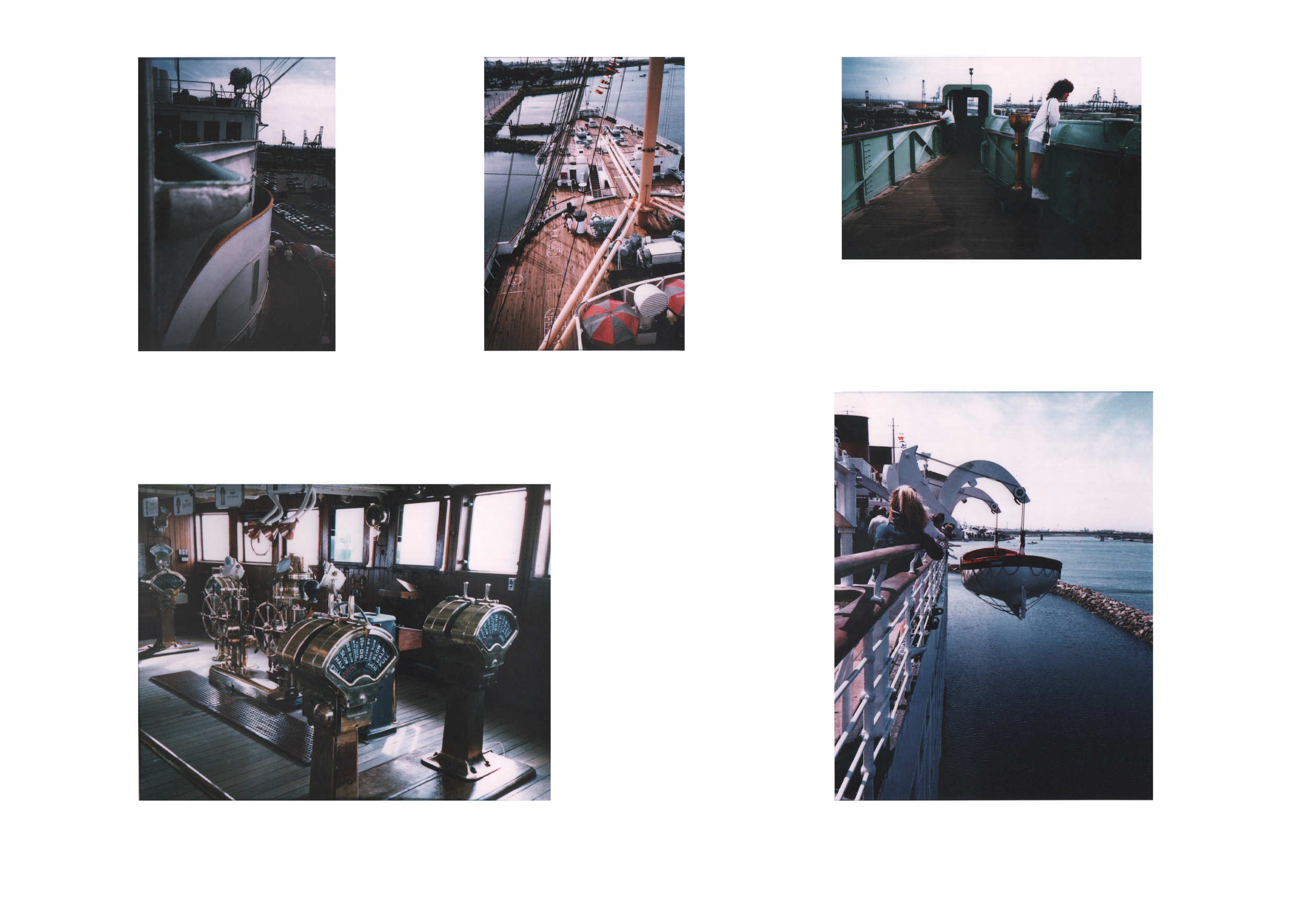
Demolition and Replacement of the Centrepoint Tower by John Millard:

The intersection of Oxford Street, Tottenham Court Road, New Oxford Street and Charing Cross Road is where The CentrePoint Tower is located in St. Giles Circus. The Circus is a large space that requires egress by pedestrians from London Underground Station, Tottenham Ct. Road - one of the most heavily travelled tube stations in London.

This study map formed the sequence of public spaces that the West End of London offers a pedestrian traveling from Trafalgar Square to Euston Center via Leicester Square, Soho Square, Seven Dials, Cambridge Circus, St. Giles Circus, Bedford Square, Fitzroy Square, and Bloomsbury Square. The planning of st. Giles Circus was informed by this experience of travelling across the West End.

This diagram shows how the tower was never meant to exist as an anomalous building on its own. The four, heroic pavilion versions of the tower create a context that make a family of buildings that are related to the tower, oozing with pedestrians. The open space invites St. Giles Church by Hawksmoor to be present, with it's passageways from Covent Garden.

As aeronautical forces began to inform the design of the tower, gargoyle-like aerofoils that move across the lower south western facade to which the prevailing south west wind traditionally had made pedestrian occupation of the outdoor plaza quite windy from wind shear as a result of the geometry of the original Centrepoint Tower.

This plan shows the shear walls that form steel sheet pile shells. These shells of two directional core ten sheet pile (a sandwich of vertical and horizontal sheet pile with an in-situ concrete core) rise out of the foundations as large tubes (with local openings) and read open as the tower increases in height.

Outdoors comes in; The transparent metal canopy that spans over the entrance lobbies of the ground floor seamlessly exfiltrates out through the weather-tight envelope of the lobby to incorporate the metal braces that constrain the movement of the aeronautical gargoyles in the z axis.

This drawing, which was derived from the actual band saw section through the 1:500 balsa model that was wind tunnel tested, is an accurate representation of the contours that successfully induce updraft when air encounters the southwestern facade at thirty kilometres per hour or more. The transfer floors occur every 30 meters and allow for disparate volumes of tenant space to occur inside of these transfer floors.

This drawing is actually based upon the 1:200 model that was tested in the wind tunnel at Kingston Polytechnic. What is not shown is the glazing skin that is supported by wind bracing and forms the weather envelope of the building. The external turbulence system shown in the foreground of the elevation is deigned to address the prevailing winds at the site by inducing updraft by channelling the laminar flowing air into an upward movement along the contours of the southwest facade.

Here in this image, the existing site can be seen with construction activity occurring in 2012 at St. Giles Circus. The context of the photo shows the British Museum in the background, Soho Square in the foreground, Bedford Square near the British Museum and Cambridge Circus to the lower right corner of the photo.

The New Centrepoint Tower, montaged into the photo above is slightly taller than the Existing Centrepoint Tower at 210 meters. The orientation is more southwesterly than the Existing Centrepoint Tower. The entire structure revolves southward as the height of the structure increases. This is similar to a plant straining to receive more sunlight, it twists toward the sun ignored to achieve more photosynthesis for food and growth.
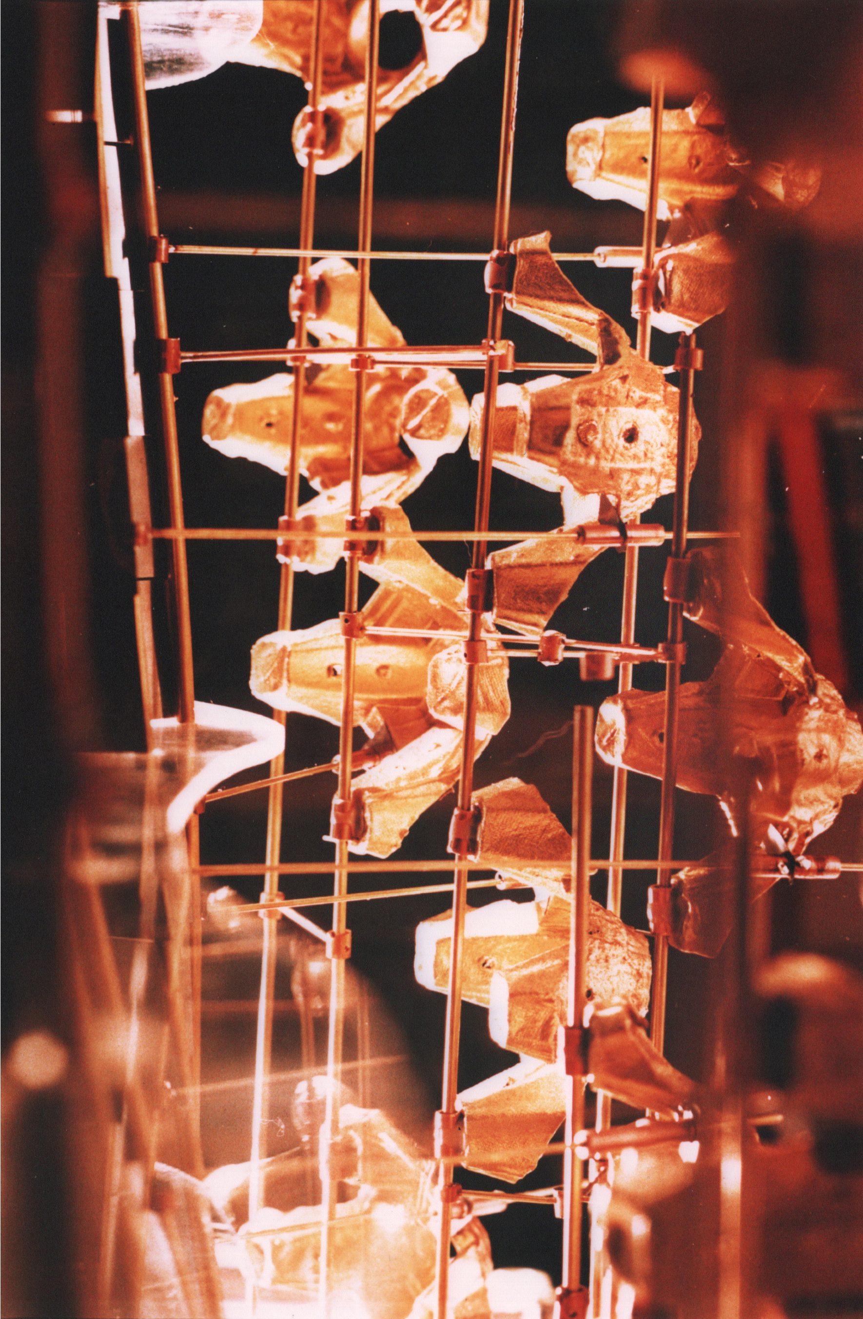
The Gargoyles, which are fabricated from special fabric and metal frames borrowed from certain Susumu Shingu Projects are designed to increase micro turbulence at the lower levels creating a shape that channels the laminar flowing air into a chute that is upward in direction. The facade of the southwest is shaped to induce this updraft. Views out of this wind screen are obstructed by these Susumu Shingu type structures and they also move in a controlled fashion, slowly rotating in the z axis as they self direct themselves into the changing wind direction.

Looking up from the entrance to the Virgin Atlantic Superstore, the New Centrepoint Tower has a curious, oblique view when seen from the north west. The smooth scoop-like shape that the south west facade reveals from this angle is curious and in contrast to the staccato presence of The Gargoyles in the External Turbulence System.

This model was clad using clear plastic by weaving the sheet of plastic in and out of these monofilament wires in order to simulate a smooth surface that accurately represented the exterior envelope of the building for use in the wind tunnel at Kingston Polytechnic. The last has been removed in this photo, but the shape of the exterior can clearly be seen forming the shape of the building.


BERLIN TRAIN HOTEL- YOU SLEEP AND STAY ON THE TRAINHOTEL


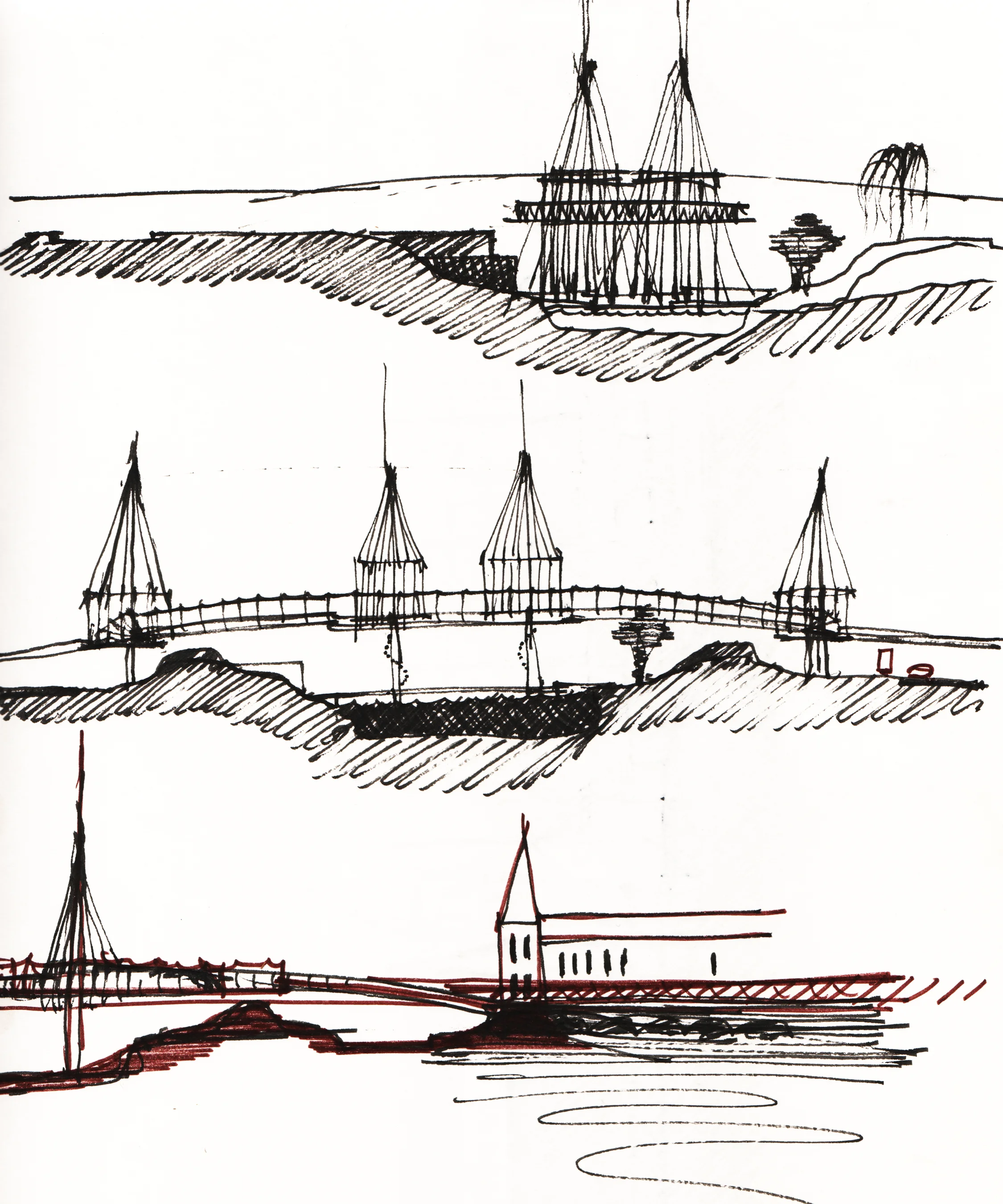


Paternoster Square Concept Development (Bend the Queen Mary around the Cathedral)


Paternoster Square Rain Screen Component Design (Reflect Sunlight onto North Facade)


Paternoster Square Multi-Use Building Schematics (Queen Mary Program Comes Ashore)


