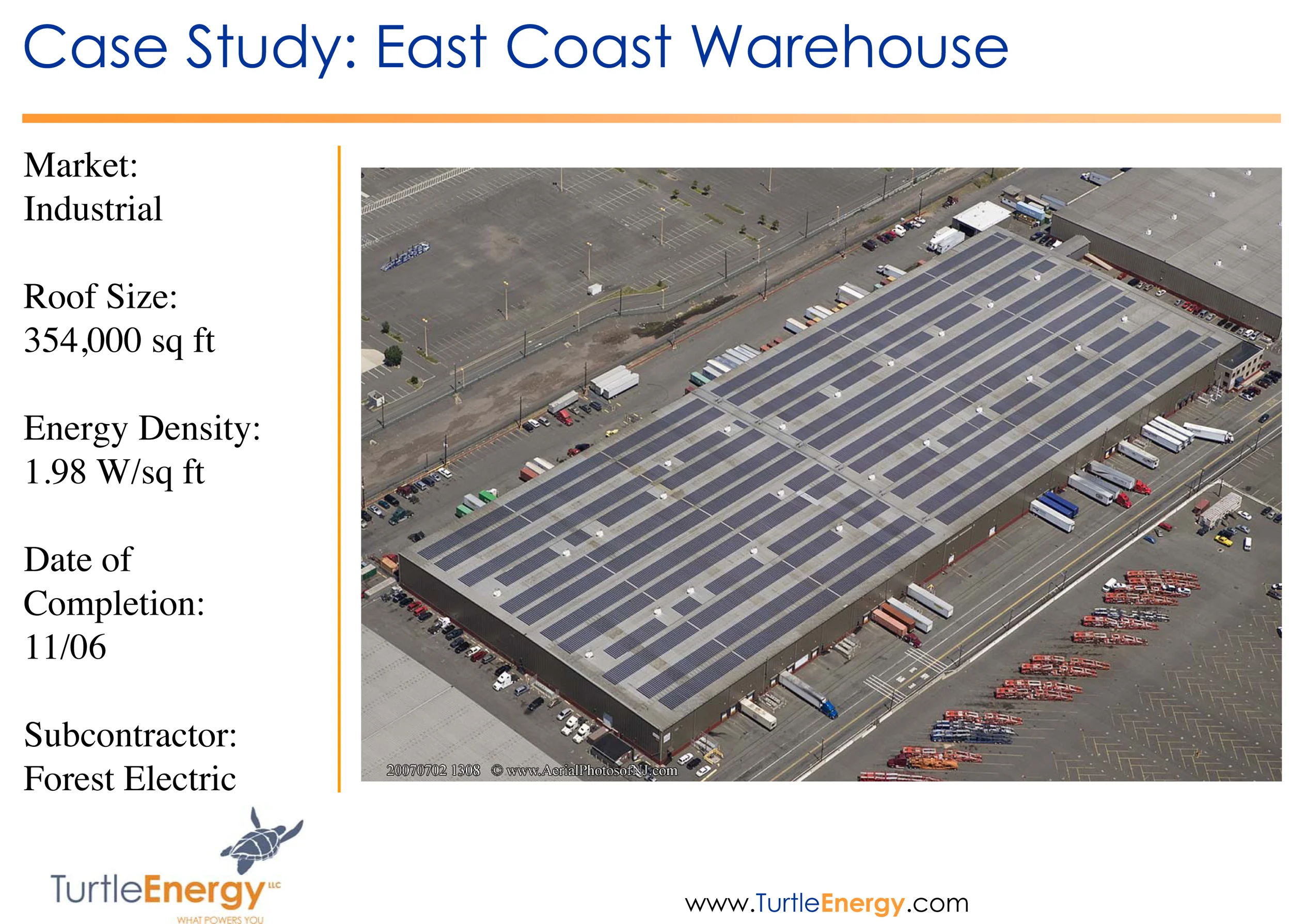
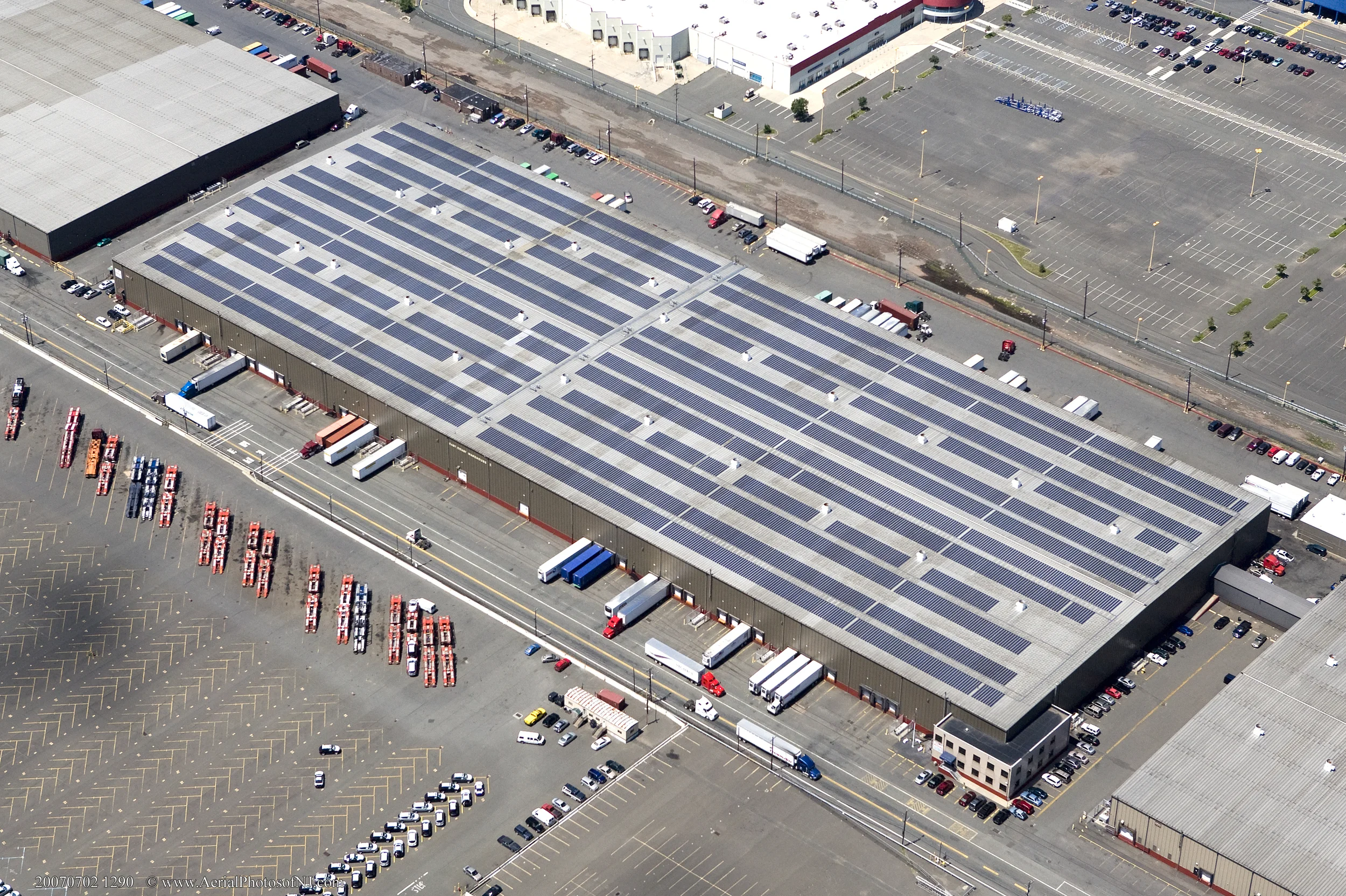
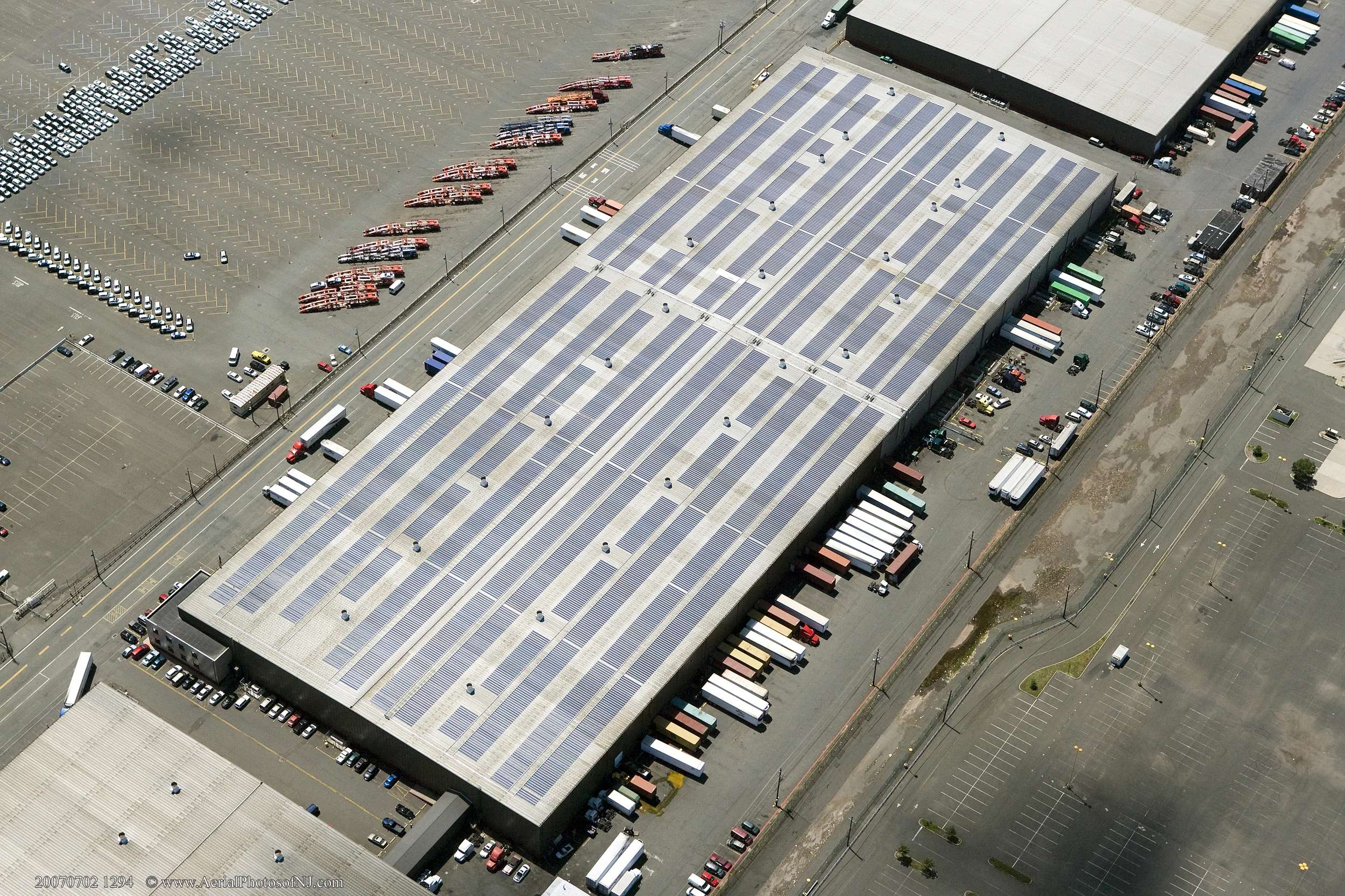
700 kW Solar Project for The Port Authority of New York & New Jersey- Completion Photos
Project Data
End-User: East Coast Warehouse
Installer: Forest Electric
Location: Port Elizabeth, New Jersey
Date of install: September 2006
Size of system in kW: 700kW
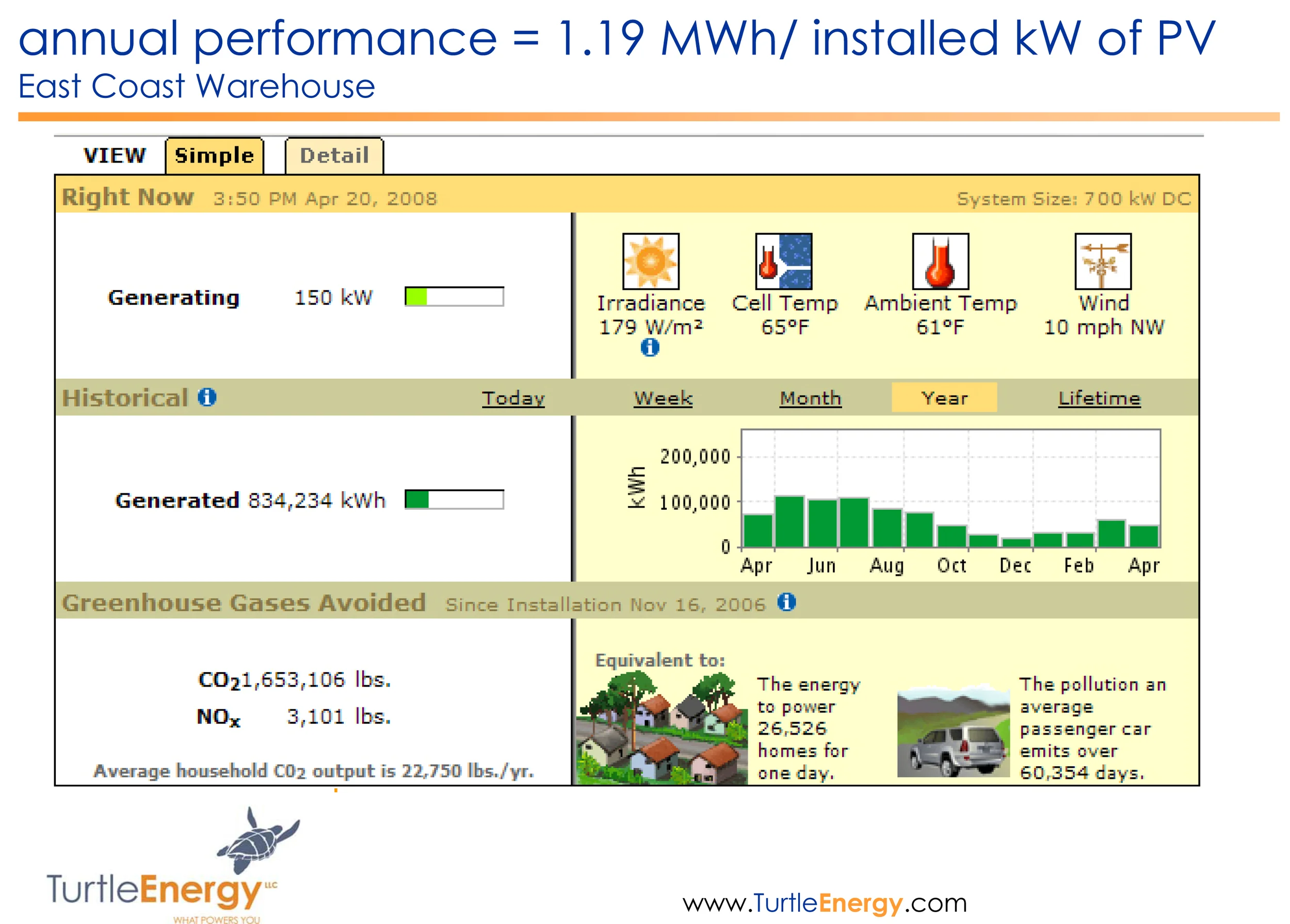
Energy produced since installation: 1.4GWh
Special Challenges Met: Building Integrated Photovoltaics
Project Brief
TEST AND COMMISSIONING PROCEDURE FOR 700KW PHOTOVOLTAIC POWER SYSTEM
East Coast Warehouse, Port Elizabeth, NJ
SECTION #1
1.1 Introduction
1.2 Safety Warnings- PV Laminates
2.3 Safety Warnings – SatCon Inverters (PCS)
SECTION #2
2.1 Initial Test and Commissioning of Solar Arrays
2.2 Inverter System (PCS) Operation and Start-up
SECTION #3
3.1 Maintenance
SECTION #4
4.1 Check lists
COMMISSIONING PROCEDURE
SECTION #1
1.1. Introduction
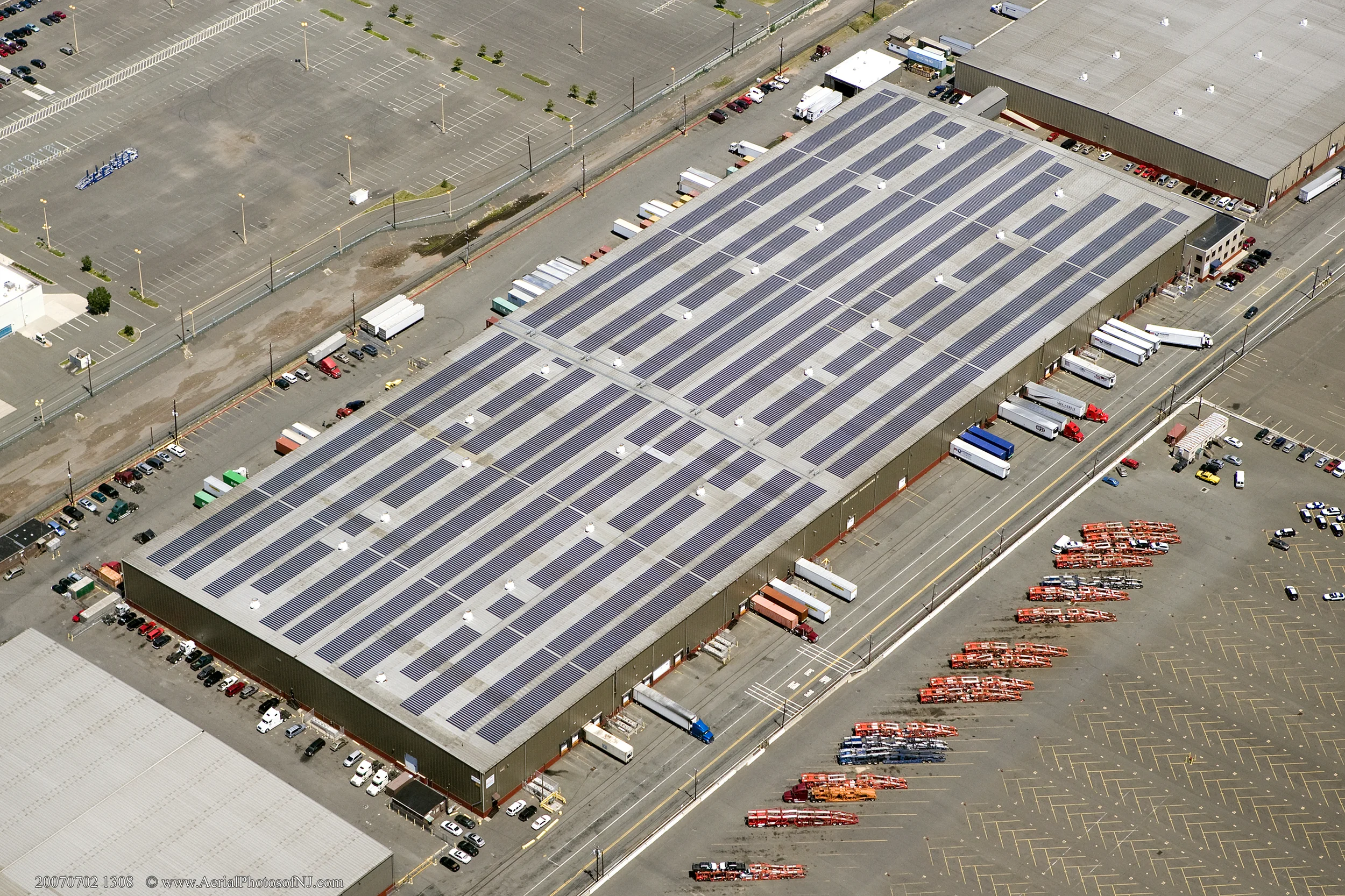
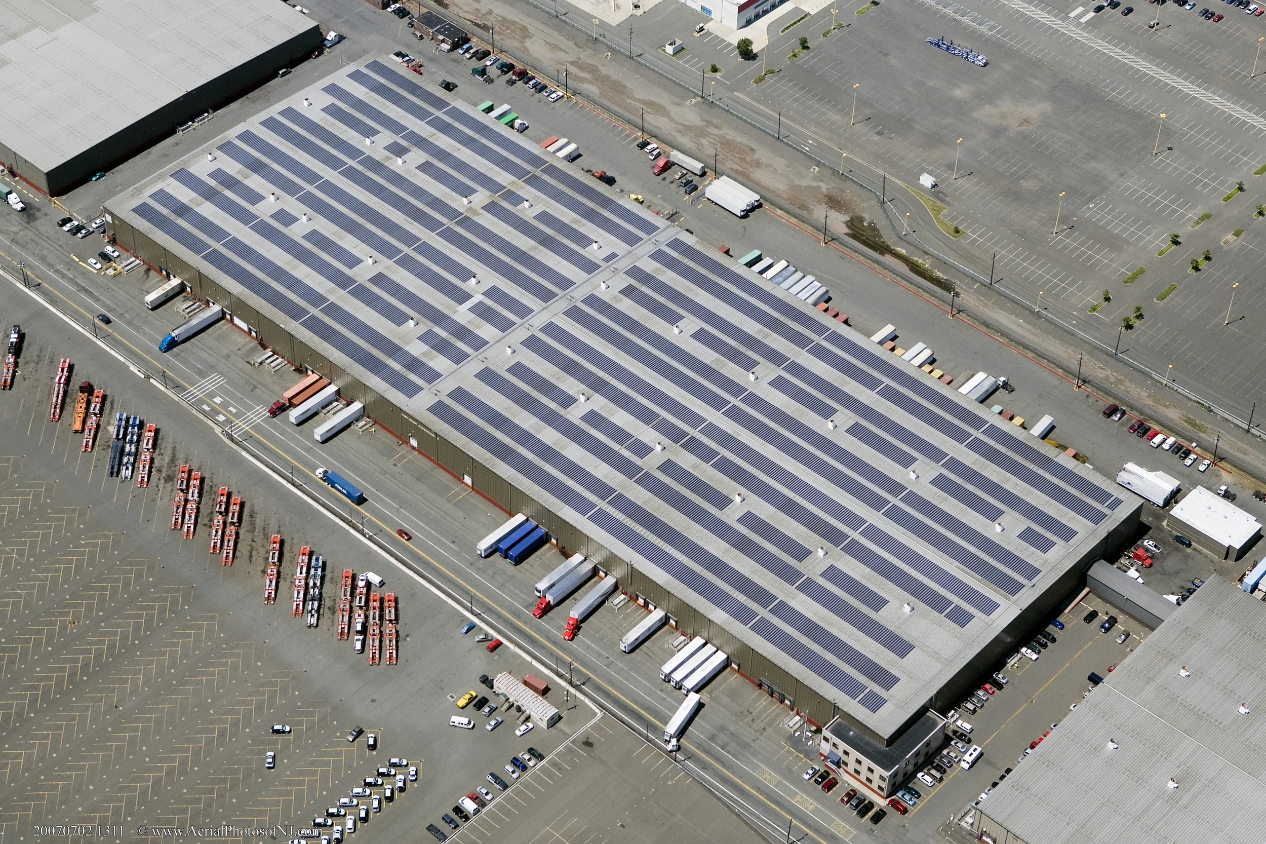
The photovoltaic power system installed on the East Coast Warehouse building at 1140 Polaris Street, Elizabeth, NJ, is a building-integrated, 700kW DC system. The major system components are as follows:
(5,148) Uni-Solar PVL-136 Photovoltaic Laminate solar panels
(36) 12-channnel combiner boxes
(12) 3-Pole, 200A, 600V, DC Disconnect Switches – fused
(3) SatCon 225kW, 480VAC Inverter/transformer power conditioning systems
(3) 3-phase, 400A, 480VAC AC Disconnect Switches - fused
The system electrical architecture is shown in the diagram below:
As shown in the above system block diagram, there are three, identical, 225kWAC subsystems that make up the complete system. The Single-Line Electrical Diagram that describes each 225kWAC subsystem is shown below:
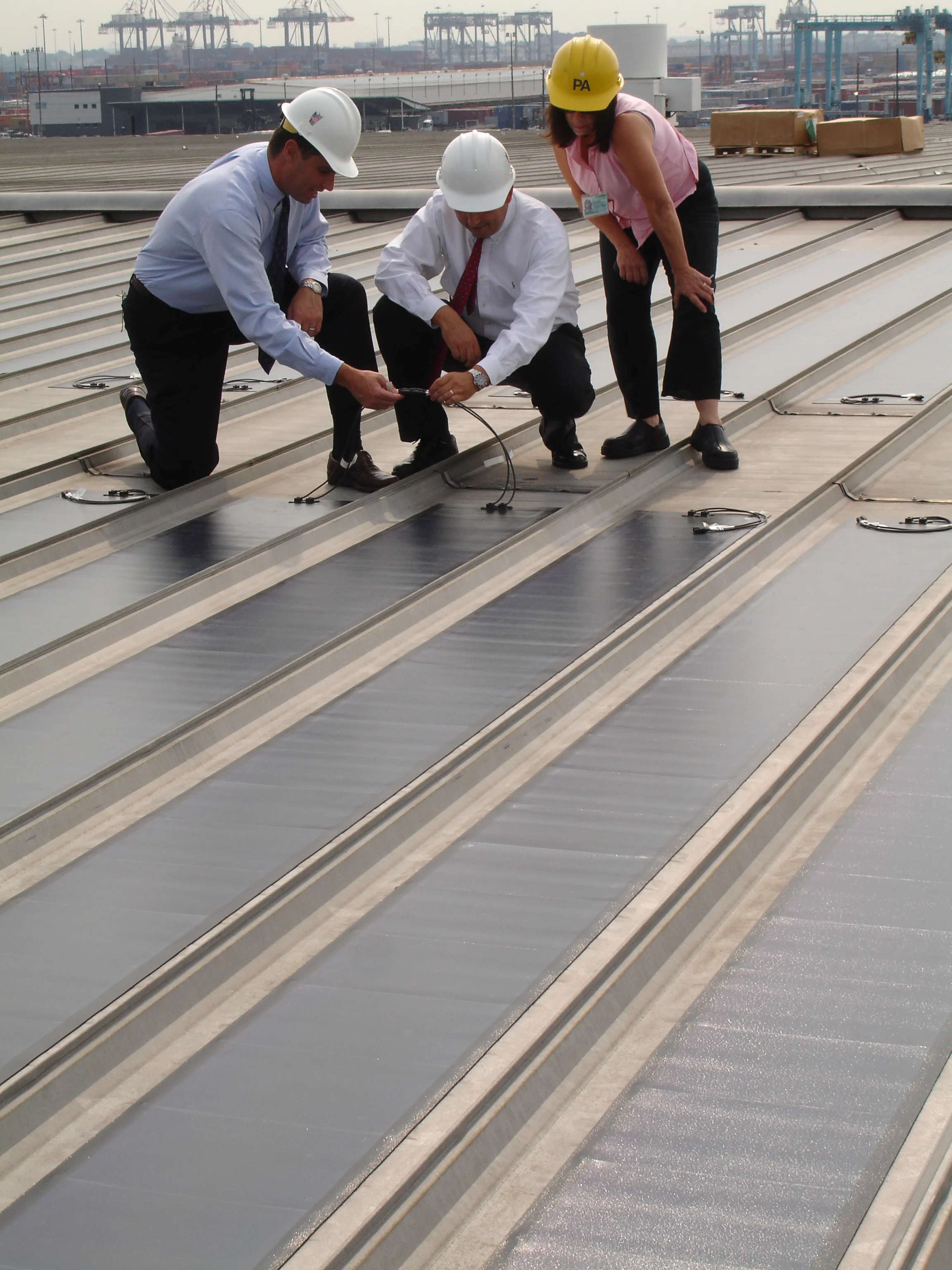
The 5,148 flexible, thin-film, photovoltaic panels are adhered directly to the standing seam metal roofing pans on the roof of the building. They are arranged in electrical series strings of 12-panels each for a combined string operating voltage of 396VDC. The string operating current is a maximum of 4.1A, under full sun (1,000 watts per square meter). This current varies from zero to 4.1A depending on the solar energy striking the surface of the photovoltaic panels.
The strings are paralleled in each of 36, 12-channel combiner boxes for a total maximum current of 49.2A at the operating voltage of 396VDC. The maximum short-circuit current in each string is 5.1ADC. The combined short circuit current for each combiner box and DC Disconnect circuit is 61.2A. This means that the maximum current that can exist in any circuit on the DC side of the system is 61.2ADC feeding a direct short circuit. The maximum operating DC current in any DC circuit is 49.2A feeding the inverter as its operating load. The output of the inverter system is 480VAC, three-phase. The maximum AC current that can be delivered by each inverter is 270A.
Summary of operating voltages and currents:
Array Operating Voltage (Vmp) 396VDC
Array Maximum Open Circuit Voltage (Voc) 554.4VDC
Array String Current (Imp) 4.1A
Array String Short Circuit Current (Isc) 5.1A
Combiner Box Current (12-string) (Imp) 49.2A
Combiner Box Short Circuit Current (Isc) 61.2A
Inverter AC Output Voltage (Nominal) 480VAC
Inverter AC Output Current (at rated output) 270A
NOTES:
During the first 8-10 weeks of operation, electrical output exceeds specified ratings. Power output may be higher by 15%, operating voltage may be higher by 11% and operating current may be higher by 4%.
Electrical specifications (±5%) are based on measurements performed at standard test conditions of 1000 W/m2 irradiance, Air Mass 1.5, and Cell Temperature of 25°C after long-term stabilization. Actual performance may vary up to 10% from rated power due to low temperature operation, spectral and other related effects.
Manufacturer has tested array string sizes up to 14 panels in extreme cold conditions without measuring an actual Voc greater than 600V.
1.2 Safety Warnings – PV Laminates
The UNI-SOLAR Field Applied PV laminates produce DC electricity when exposed to the sun or other light sources. The power from one individual panel is not considered hazardous. However, when connected in series and/or connected in parallel, the potential shock hazard increases. In this case, the string voltage is near 400VDC.
Observe safe electrical practices at all times. Use insulated tools.
Observe safety precautions when accessing and walking on the roof. Avoid standing closer than 6’ from the edge of the roof. Do not walk on wire covers.
Make sure that all sources of electrical current have been disconnected prior to servicing or altering the electrical wiring connections. There are often multiple sources feeding a single point.
Avoid dropping any sharp objects on solar PV laminates.
Avoid standing on the PV laminates whenever possible. If unavoidable, wear clean, soft-soled shoes and walk in the center of the panel. CAUTION!! Laminates are very slippery when wet.
1.3 Safety Warnings – SatCon Inverters (PCS)
The PCS contains lethal voltages. All power switches should be opened and inverter ES switch placed in the “OFF” position prior to opening the cabinet doors. To avoid the potential of electrical shock, do not open cabinet doors until 5 (five) minutes after disconnecting all sources of supply.
An incorrectly installed PCS may result in equipment damage or a reduction in product life. Incorrect wire sizing, inadequate supply, or excessive ambient temperatures may result in system malfunction.
The PCS units contain ESD (Electrostatic Discharge) sensitive parts and assemblies. Static control precautions are required when installing, testing servicing or repairing these units.
The PCS enclosure contains exposed high voltage conductors. The enclosure door should remain locked, except during maintenance or testing by service personnel. To avoid the potential of electrical shock, do not open cabinet doors until 5 (five) minutes after disconnecting all sources of supply.
Improper phase connections, paralleling, or use of the PCS can damage the equipment. Precautions should be taken to ensure that the PCS units have been properly installed.
SECTION #2
Initial Test and Commissioning
Turn-off (Open) all DC and AC disconnect switches located in the building electrical room. Open all AC and DC disconnect switches on Inverters A, B, & C.
Visual Check of roof surface
Examine the surface of the roof to verify the following:
No significant debrisSolar panels are adhered and arranged in straight rows (north-south).Wire covers are arranged in straight rows (north-south)
2.1.3 □Visual Check of mounting brackets for DC combiner boxes
Observe that the combiner boxes are securely mounted to the Uni-Strut brackets
Observe that the mounting assemblies are secured to the standing seam roofing
2.1.4 □Visual check of all PV panel interconnections
With wire cover assembly lids removed, perform a visual check of PV panel strings and sub-array wiring. Wiring is to be one pair of “home-run” wires from each 12-panel string to the appropriate combiner box. Note: USE-2 Wire, which is rated for external, surface wiring applications with exposure to water, oil, and UV, is used as the standard PV panel wiring. In this case, a wire cover is implemented for convenience and aesthetics.
2.1.5 □Open string circuit fuses
Open the door of each of the 36 combiner boxes and ensure that the pop-up fuse holders are all in the “open” position. With a voltmeter, check for open circuit voltage on each array string (far left set of wire connections at each of the 12 fuse holders). Open circuit voltage should be greater than 450VDC and should be within 20V of each other on a string-to-string basis. Record the measured voltage for each PV string. (Checklist Worksheet in Section 4)
2.1.6 □Check combiner box connections
Visually check the electrical connections in each combiner box for proper wire connections. Red wires from PV array should be connected to the fuse blocks and black wires should be connected to the negative lug(s). With the fuses in the “open” position, check the positive and negative connections at the output of each combiner box for tightness (no specific torque spec.).
2.1.7 □Check combiner box ground connection
Verify that the green ground wire is connected the combiner box ground lug.
2.1.8 □Check DC Disconnect terminals
With the Combiner Box fuses in the “open” position, open each DC Disconnect Switch covers and check all electrical connections in each of the twelve, DC disconnect switches. Tightening torque on these electrical connections should be 55 to 65 foot-pounds.
2.1.9 □Close Combiner box fuses
Place all DC Combiner Box fuses in the “closed” position.
2.1.10 □Check DC disconnect connections
Make sure all DC Disconnect Switches are in the “off” position with the covers open. With a voltmeter, check the open circuit PV array voltage at each lug, near the top of all 12 DC disconnect switches. The measured voltages between the positive and negative terminals should be consistent with the voltages measured at the combiner boxes. Record the measured open circuit voltage at each lug while all switches are in the open position. (Checklist Worksheet in Section 4)
2.1.11 □Check connections & torque at re-combiner panel
Open the cover of the DC input re-combiner panel. (see photos on page 14) Visually check all connections. Ensure that the DC disconnect switches are in the “open” position. Check the torque on each of the twelve +DC input lugs and –DC input lugs in the re-combiner panel. Torque should be consistent with those shown in Table 2.1
2.1.12 □Close DC Disconnect Switches
Close each DC Disconnect individually and check for the open circuit voltage at the corresponding terminals in the inverter re-combiner panel. Verify that the markings on the DC Disconnects are consistent with the connections in the inverter re-combiner panel. There are four DC Disconnects connected to each of the three inverters and three array circuits (combiner boxes) per DC Disconnect. Measure and record the DC voltage measurements at each. (Checklist Worksheet in Section 4)
2.1.13 □Open AC disconnects
Make sure that all three AC Disconnect Switches are in the “Off” position. The AC Disconnect Switches are wired directly to the building main bus so that side of the switch terminals will be “hot”.
2.1.14 □Check AC power connections visually
Open disconnect switch cover and visually check all AC power connections at each AC Disconnect Switch. Open the AC input cover on the left end of the inverter and check the three-phase connections between the inverter and the AC Disconnect Switch (see photo on page 15). Torque should be consistent with values shown in Table 2.1.
2.1.15 □Check AC fuses
Make sure that the 300A AC Fuses are in place and properly secured.
2.1.16 □Check AC connections at inverter (torque)
Torque should be consistent with those shown in Table 2.1
2.1.17 □Check ground connections (torque)
Check all earth ground connections. Torque should be consistent with those shown in Table 2.1
TABLE 2.1 – Torque Specifications for SatCon Inverter
2.1.18 □Close AC disconnects
2.2 Inverter System (PCS) Operation and Start-up
Note: Please read the Operating Instructions before proceeding with the Initial Power Up steps.
Initial Power Up – Repeat for each of three inverters
Close AC Breaker CB1Wait 10 seconds for processor initialization and check the voltage displayed on the display screen (use OIT, Main Menu-Metering-AC Line).Check that the unit is not faulted (use OIT, Main Menu-Diagnostics-Next Fault).Check that the unit is testing the grid (use OIT, Main Menu-Page Down-Page Down).Close the DC Disconnect Switch DS1.Check that the PCS is displaying the PV voltage correctly (use Main Menu-Metering-DC PV).Check that the unit is checking the DC input voltage (use Main Menu-Page Down-Page Down).Check tha the PCS is in ENABLE condition (Main Menu-Operation); in case it is not in ENABLE condition, use Page Down from the same screen, position the promper on the PCS EN/DIS line, press CLEAR, edit “1”, and press ENTER. Use again Page Down to go to the next screen SAVE SETTINGS, press CLEAR, edit “1”, and press ENTER.
2.2.1 Operating Instructions
This section describes the operating instructions and the sequence of events of PCS operation. The PCS can be operated either from the local control panel OIT or from a PC through modbus communication between the PC and the PCS Digital Control Board.
2.2.2 General
The power conditioning system follows the line frequency and the voltage set by the utility while delivering power to load. The PCS is designed for rated power and performance at +/-10% of the nominal line voltage and +/-2% line unbalance voltage.
The PCS meets or exceeds the requirements of IEEE 519-1992 Standard for voltage and current power quality.
The unit operates as AC current controlled voltage-source inverter. The inverter is synchronized with the phase of the line voltage automatically through controlling the current reference signal, which is synchronized with the line. This allows the control of power factor, real power and reactive power.
The PCS adjusts the reactive power to the line as per the KVAR or reactive current demand signal. Real and reactive power accuracy is within +/-2% of the rated demand.
In the case that voltage and/or frequency of the line becomes less than or more than the specified range, the unit stops and is disconnected from the line and the PV arrays. The Voltage & Frequency Output Protection is provided by the PCS digital control board DPCB, tested by UL to UL1741 standards.
2.2.3 PCS Operating States
The PCS has the following operating states:
a) Sleep Unit is stopped, contactors are open, no fault.
b) Pre-drive PCS pre-charges and regulates the DC link voltage.
c) Drive PCS is running. During this state the PCS generates real power to the grid by tracking the maximum power point of the PV or follows AC active current settings that are set from the OIT. Meanwhile, the PCS also controls AC reactive power by reactive power setting that is set from either the OIT or the remote communication.
d) Fault -Unit critical fault, PCS will shutdown and can only be reset manually.
2.2.4 PCS Control
2.2.4.1 Enable/Disable the PCS
The PCS has a setting for Run enable or disable. PCS can be enabled or disabled from the local controller OIT or the remote communication command. When the PCS is disabled, it cannot run. The default setting when the logic powers up can only be changed from the local OIT.
2.2.4.2 Start the PCS
When all of the following conditions are satisfied, the PCS will start automatically.
1) The PCS is in Sleep state (i.e. no fault).
2) The PCS is enabled.
3) The grid is OK that means the voltage and frequency of the grid has been within specification for more than 5 minutes.
4) The DC input voltage has been higher than a minimum voltage (VDC1-MINIM can be set from OIT) for more than 30 minutes (VDC1-MIN TM can be set from OIT) or higher than a higher threshold voltage (VDC1-TH can be set from OIT) for more than 10 minutes (VDC1-TH TM can be set from OIT).
The following describes the sequence of events during starting of the PCS:
1) PCS closes the AC charging contactor (ACM) and the pre-charge action will take place. PCS enters into Pre-drive state. If the DC link voltage does not reach pre-charge value within 30 seconds, the unit will fault out as a Pre-charge fault .
2) After 10 to 30 seconds, DC link capacitors are charged. PCS closes AC contactor CR2 .
3) After 2 seconds, Pre-charge contactor ACM is opened.
4) After 3 seconds, PCS enables gating to the inverter and Power Generating LED on the front door starts flashing. PCS will regulate DC link voltage to 350Vdc.
5) After 5 seconds, PCS starts to regulate DC link voltage to DC input voltage plus 10Vdc.
6) After 5 seconds, PCS closes DC contactor CR1A .
7) After 2 seconds, PCS enters into Drive state. PCS will regulate DC link voltage and DC input current to track maximum power point if MPPT is enabled or PCS will follow DC link voltage command and AC active current command if MPPT is disabled.
2.2.4.3 Stop the PCS
Any one of the following events will stop the PCS and the PCS will go in Sleep state.
1) Fault(s)
2) PCS Disable – Command is provided from the local controller (OIT) or the remote controller
3) PCS detects a line fault (i.e. line over/under voltage or frequency specification
4) DC input voltage is lower than its limit.
5) DC input current has been zero for longer than 32 seconds (IDC-IN-ZERO can be set from OIT) when the PCS is in Drive State
6) AC output real power has been negative (i.e. PCS receives power from the grid) for longer than 30 minutes (KW-LINE-TM can be set from OIT) when the PCS is in Drive State
The following describes the sequence of events during stopping the PCS:
1) Inverter gating will be stopped.
2) Contactors CR1A & CR1B and CR2 open to isolate the PCS from the PV and the grid.
3) PCS goes into Sleep State
What has caused the last stop can be seen in the OIT Main Menu Operation screen.
2.2.5 Fault Shutdown of the PCS
Note that all the faults are latched and can be reset from the local or remote controller.
The following describes the sequence of events during fault shutdown:
1) Inverter gating will be stopped.
2) Contactors CR1A & CR1B and CR2 open to isolate the PCS from the PV and grid.
3) PCS is in Fault State
4) The PCS faults are displayed in the OIT Main Menu Diagnostic screen.
2.2.6 E-Stop of the PCS
The Emergency Stop can be generated from the local E-Stop push button on the door of the PCS or from the remote communication command.
The following describes the sequence of events during E-STOP:
1) Inverter gating will be stopped.
2) Contactors CR1A & CR1B and CR2 open to isolate the PCS from the PV and grid.
3) PCS is in Fault State.
2.2.7 Reset the PCS
When the PCS is in Fault State, it needs to be reset. Resetting the PCS can be done from the local controller OIT or from the remote communication command.
DC INPUT RECOMBINER PANEL
INVERTER AC INPUT TERMINALS
3.0 Maintenance
3.1 Care of PV Laminates on Steel Roofing Pans
If parts of the solar panels become separated from the metal roofing pans, clean the roofing pan surface under the part of the solar panel that has lifted and apply a black, roofing adhesive caulk. Carefully press the solar panel into the adhesive caulk. Use a J-Roller to apply even pressure over the separated area.
