Emerald Street Redevelopment (feasibility study)
Architecture Firm: Arup Associates
Client: The Harpur Trust
Site: Holborn, London
Date of Project: 1989
Project Summary:
Summary: JBM's role on this project in 1989 was: to provide a site analysis of the urban design issues together with the principal architect, Richard Frewer, to produce a schematic design package of drawings and a model and present the scheme to the client, The Harper Trust.
In 1989 The Harper Trust, real estate developers of Emerald Street Development approached Arup Associates architects to provide a concept for a low-rise office building that would be suitable for occupation by Arup Associates.
Initially, Arup Associates had expressed an interest in occupying the proposed development. John Millard had recently completed RIBA Part 1 and was employed by Arup Associates in Group Six. Millard and the Principal-in-charge of the project were the first two architects affecting the initial concept.
The project was shelved after this initial schematic proposal in 1989. The building was never completed.
John Millard's Role-
Role by John Millard: 1) Originate all Schematic drawings, 2) Part of a team of two architects, JM assisted the principal in charge of the design, 3) Coordinate Engineering Disciplines, 4) Produce all Schematic Phase Drawings for presentation and approval by Owner, The Harper Trust
Project was mothballed in 1989 and not constructed to date.
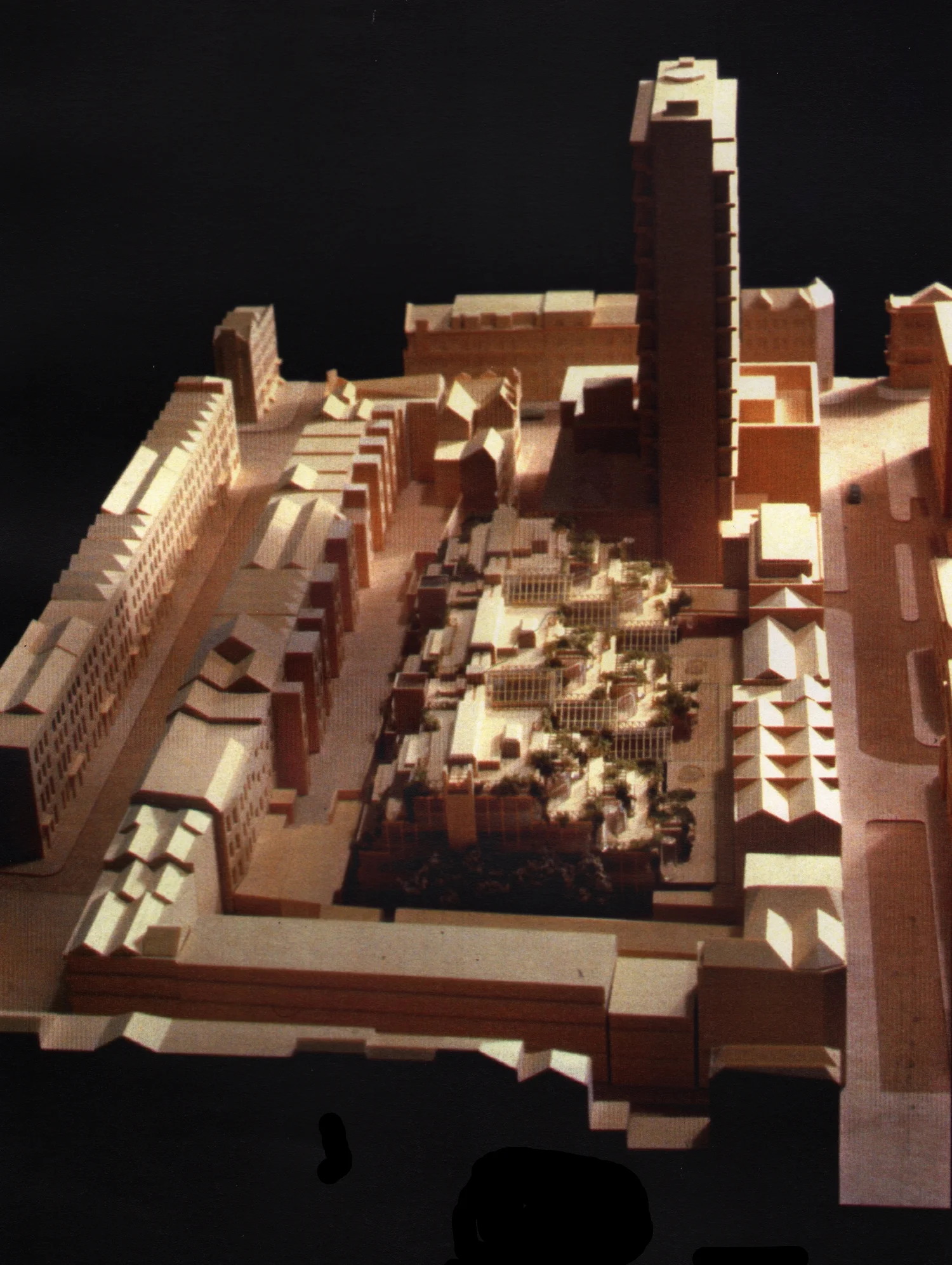
Figure 1: Emerald Street Redevelopment Site Model: Proposal required a road closure of a Central London Mews called "Emerald Street".
When I was a new student at the Architectural Association School of Architecture in 1984, I was required to register with the Holborn office of the Metropolitan Police (tall building in the background of the model above) as a resident alien. Five years later, I was privileged to join Unit 6 at Arup Associates and work on a redevelopment of this urban context which included the closure of a mews adjoining the Police Station in Holborn where I registered as a resident alien. (Model by Arup Model Shop)

Figure 2: Schematic North Elevation- Stepped massing provides for exterior access, fire egress, natural light and landscaping opportunities across a wide roofs cape. (Drawing by John Millard)
The building was intended to become the new offices for Arup Associates and the height restrictions related to Rights of Light easements among other height restrictions lent the project to a modest floor to area ratio suitable to the Arup Office Culture. (Drawing by John Millard)

Figure 3: Emerald Street Today-
The existing urban context shows the road that would have to be closed, buildings that would have to be demolished in order to construct the proposal shown above. (Model by Google Earth)
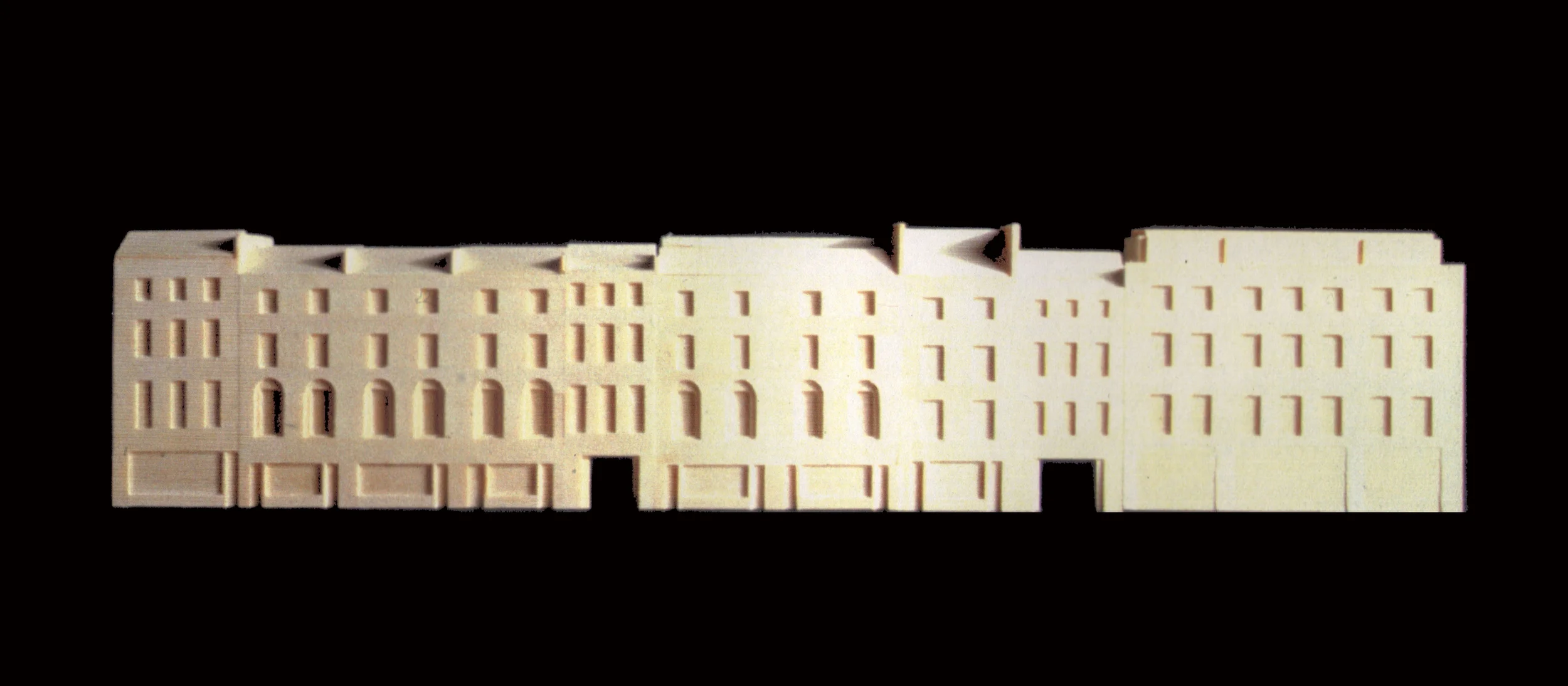
Figure 4: Lamb's Conduit Street Terrace Houses are the Frontage for the Emerald Street Development.
The ground floor openings shown on the model are the pedestrian entrances to the development and coincide with the Entrance Atriums in the Emerald Street Development. (Model by Arup Model Shop)
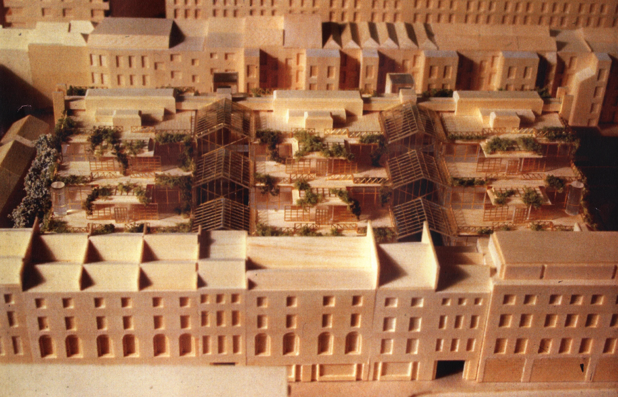
Figure 5: Elevated view over Lamb's Conduit Street Terrace Houses (Model by Arup Model Shop)
The model demonstrates the discrete presence that the Emerald Street Project has while tucked away behind the foil created by the Georgian Era Terrace Houses. (Model by Arup Model Shop)
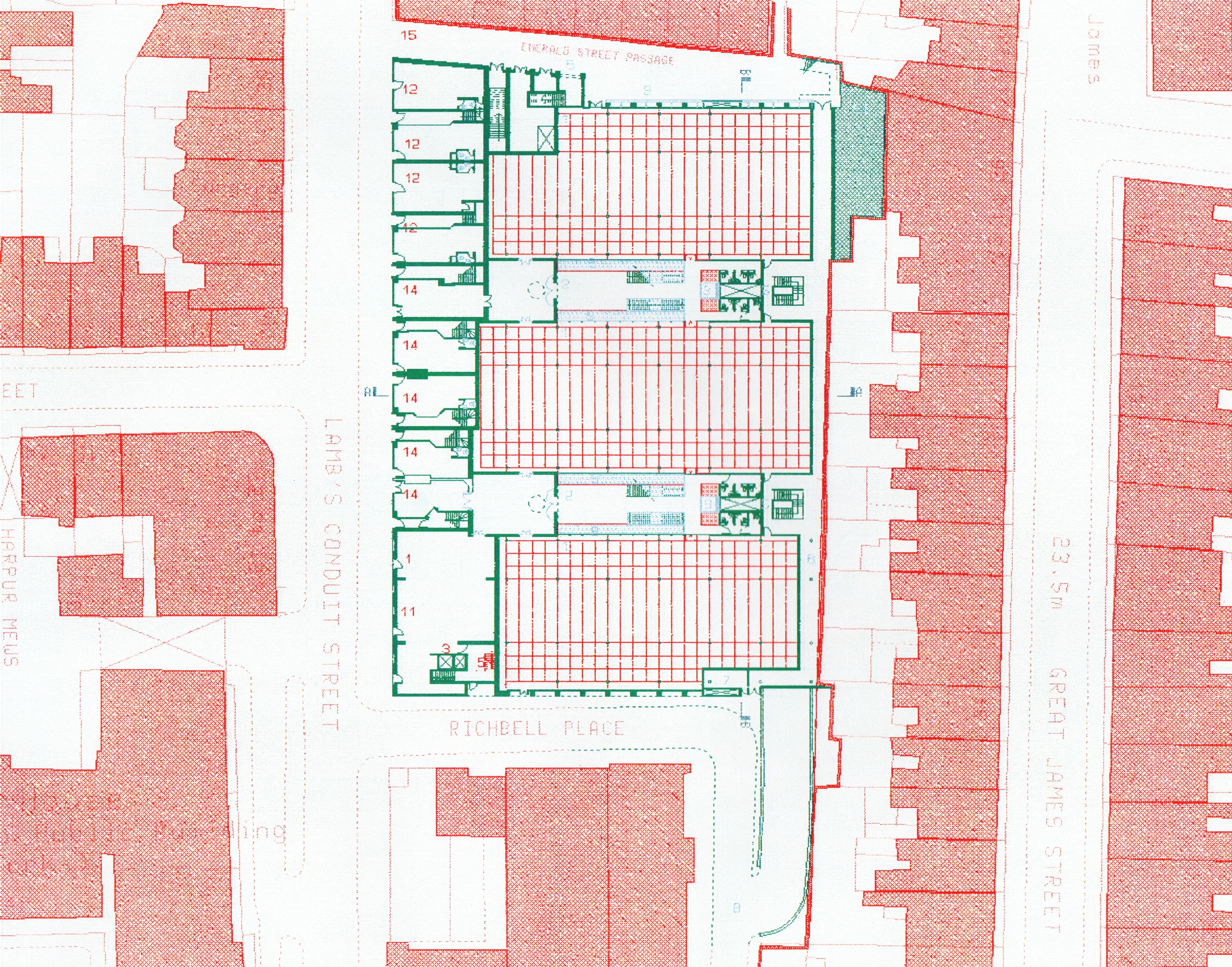
Figure 6: Ground Level Site Plan
Drawing shows various entrance points for pedestrians and vehicles as well as means of escape route from stair cores and ground floor occupancies. (Drawing by John Millard)
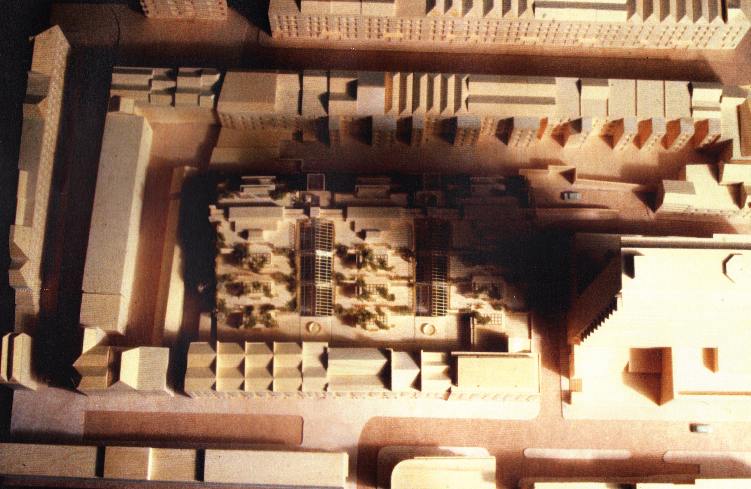
Figure 7; Site Model from above- rights of light for adjoining owners...
The shadow of the existing Police Tower on the proposed development.was not a development constraint for the police station but was certainly a constraint for the Emerald Street Development. (Model by Arup Model Shop)
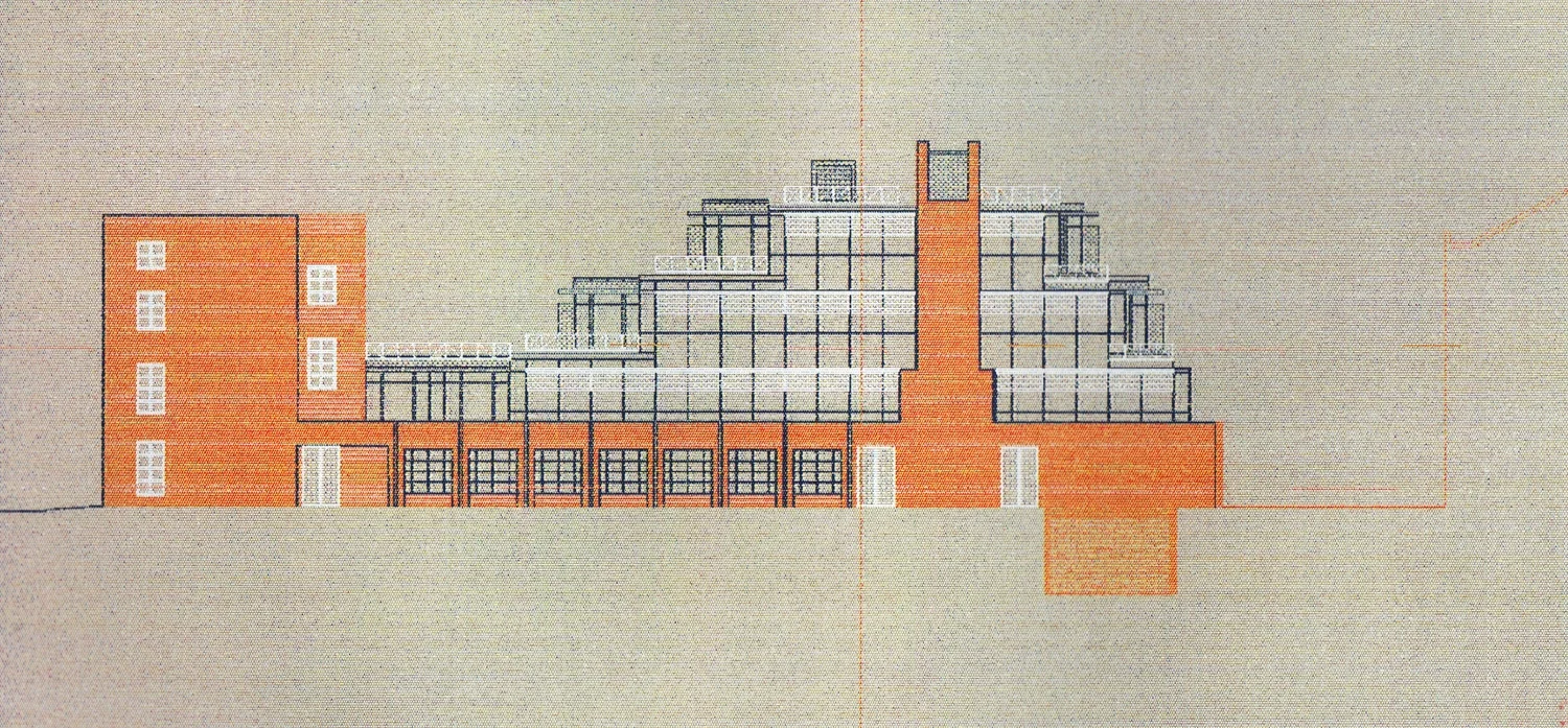
Figure 8: South Elevation of Emerald Street Development (Drawing by John Millard)
Materials: Red Brick, Steel & Glass (Drawing by John Millard)
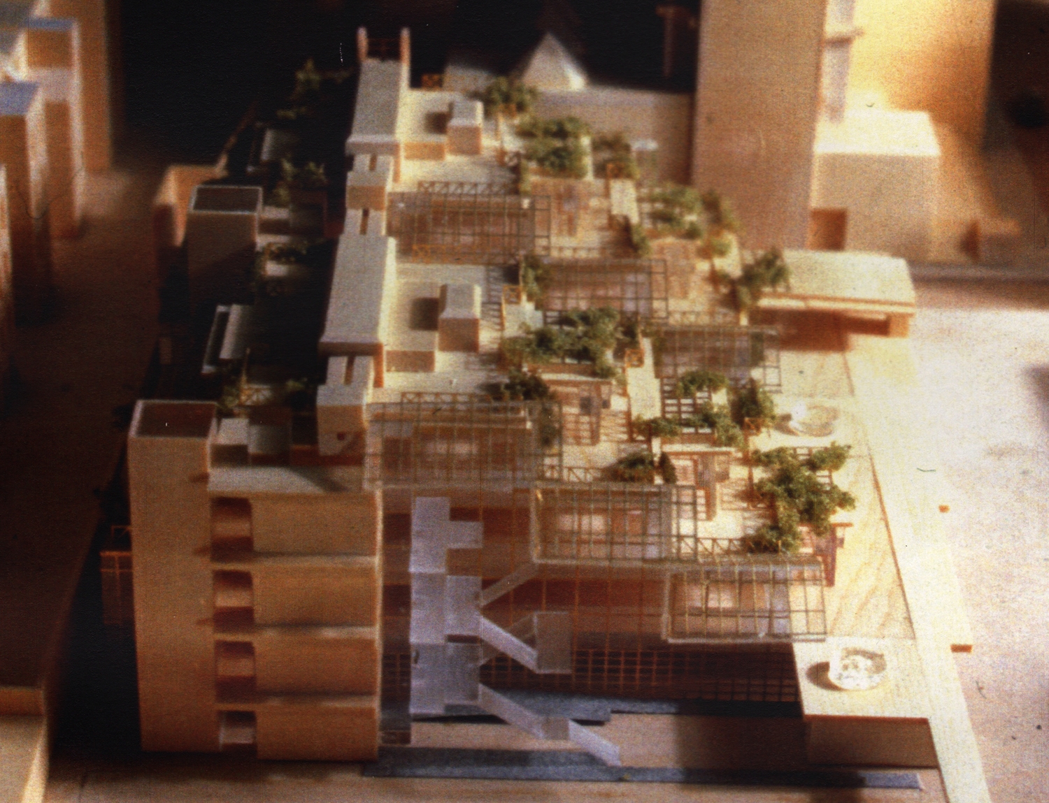
Figure 9: Exposed Section through Entrance Atrium on Emerald Street Model
The three building structures form two voids that are opportunities for entrances that were cultivated as atriums with glass canopies and elevator shafts that frame the staircases. (Drawing by John Millard)
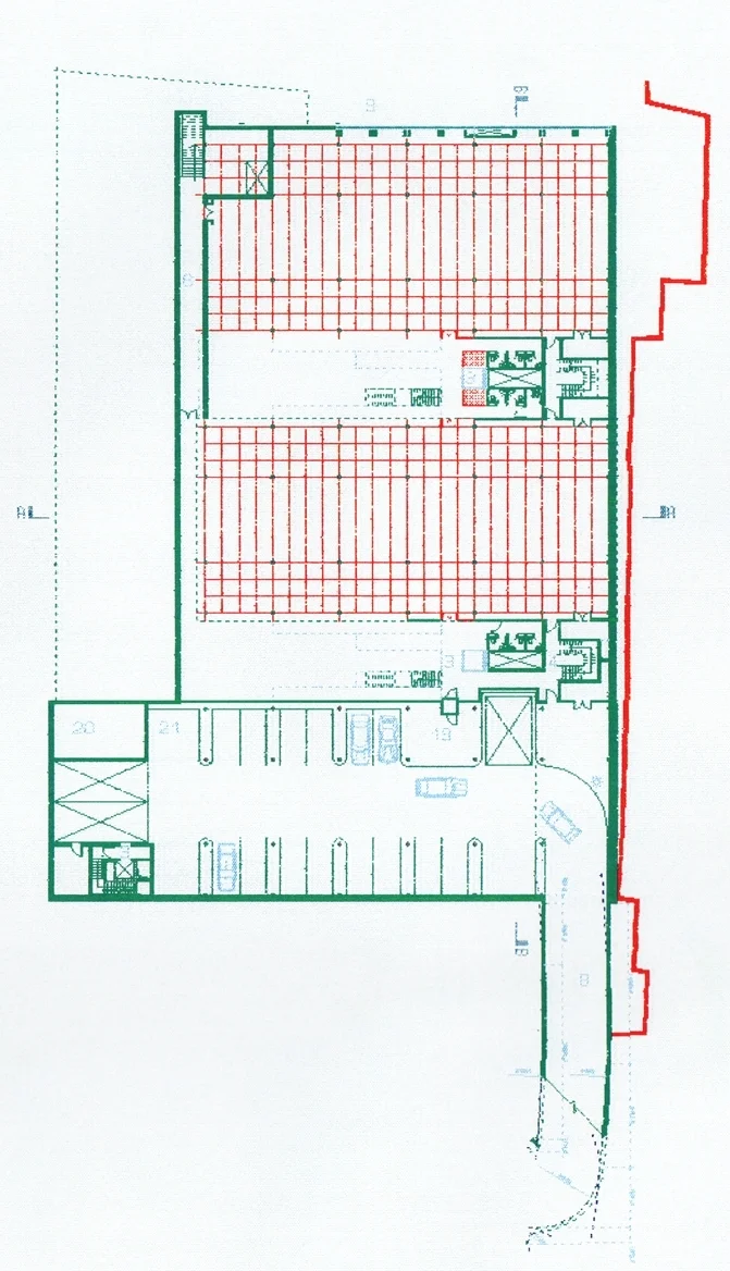
Figure 10: Lower Level Plan
The significant additional gross area available in the Lower Level Plan, and the ability to deliver natural light to this level from the two atria at ground level- tipped the efficiency of this project into the "feasible" category when reviewed by the client. Even minimal, on site parking also added value to the mixture of retail and corporate space. (Drawing by John Millard)
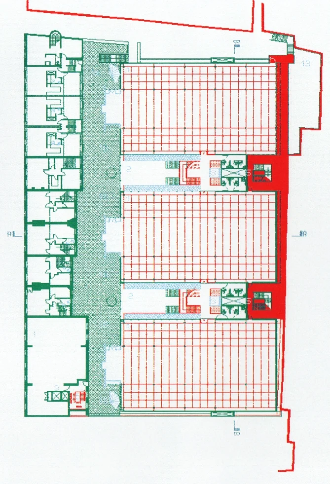
Figure 11: First Floor Plan
The elevated terrace that formed a garden outside the first floor conference rooms also provides circulation space between the buildings as well as means of escape. (Drawing by John Millard)
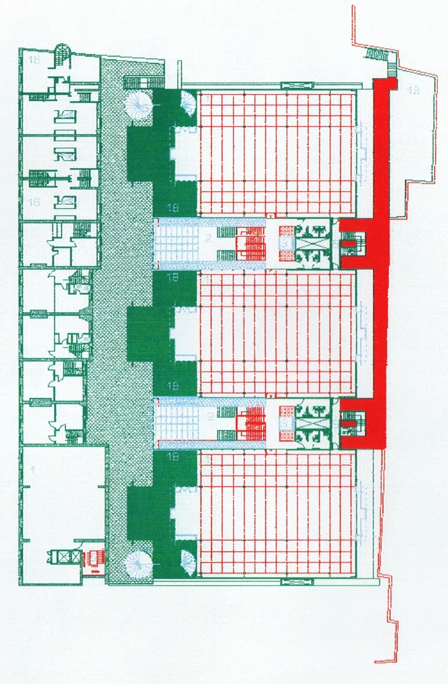
Figure 12: Second Floor Plan-
The dark green areas are outdoor terraces that allow for green roofscape and natural ventilation through operable glazing in the conference spaces. Means of escape via code compliant circular stairs at the extreme north and south of the development allow for minimal cores. (Drawing by John Millard)
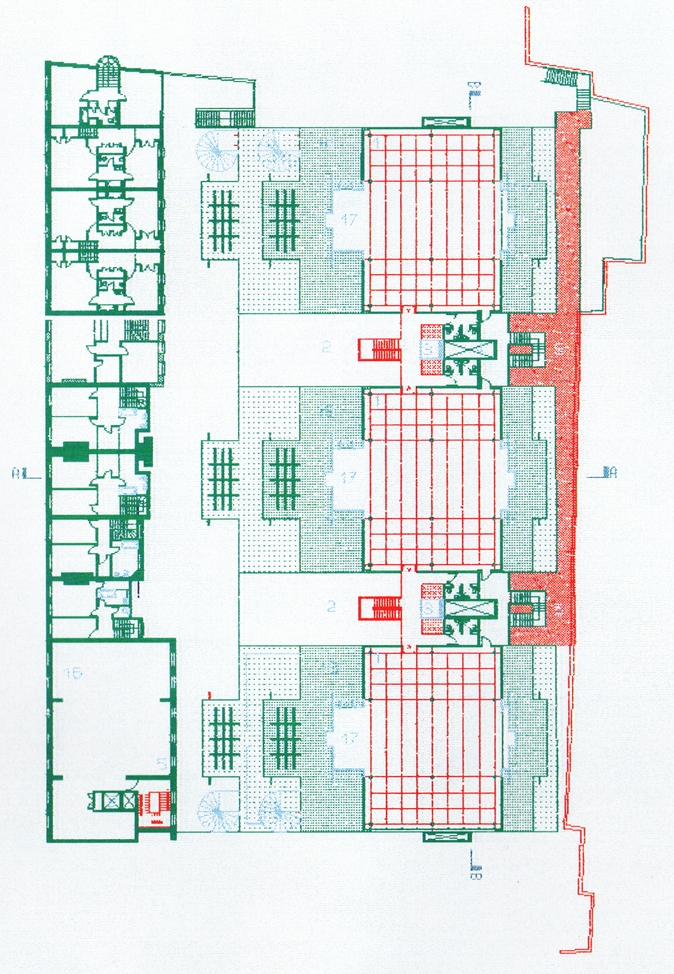
Figure 13: Third Floor Plan
The upper floors are all served with HVAC, Plumbing and Power via the steel service towers that negotiate the transition and distribution of services into the sub-floor plenum where conditioned air and wiring are delivered to each office module. (Drawing by John Millard)
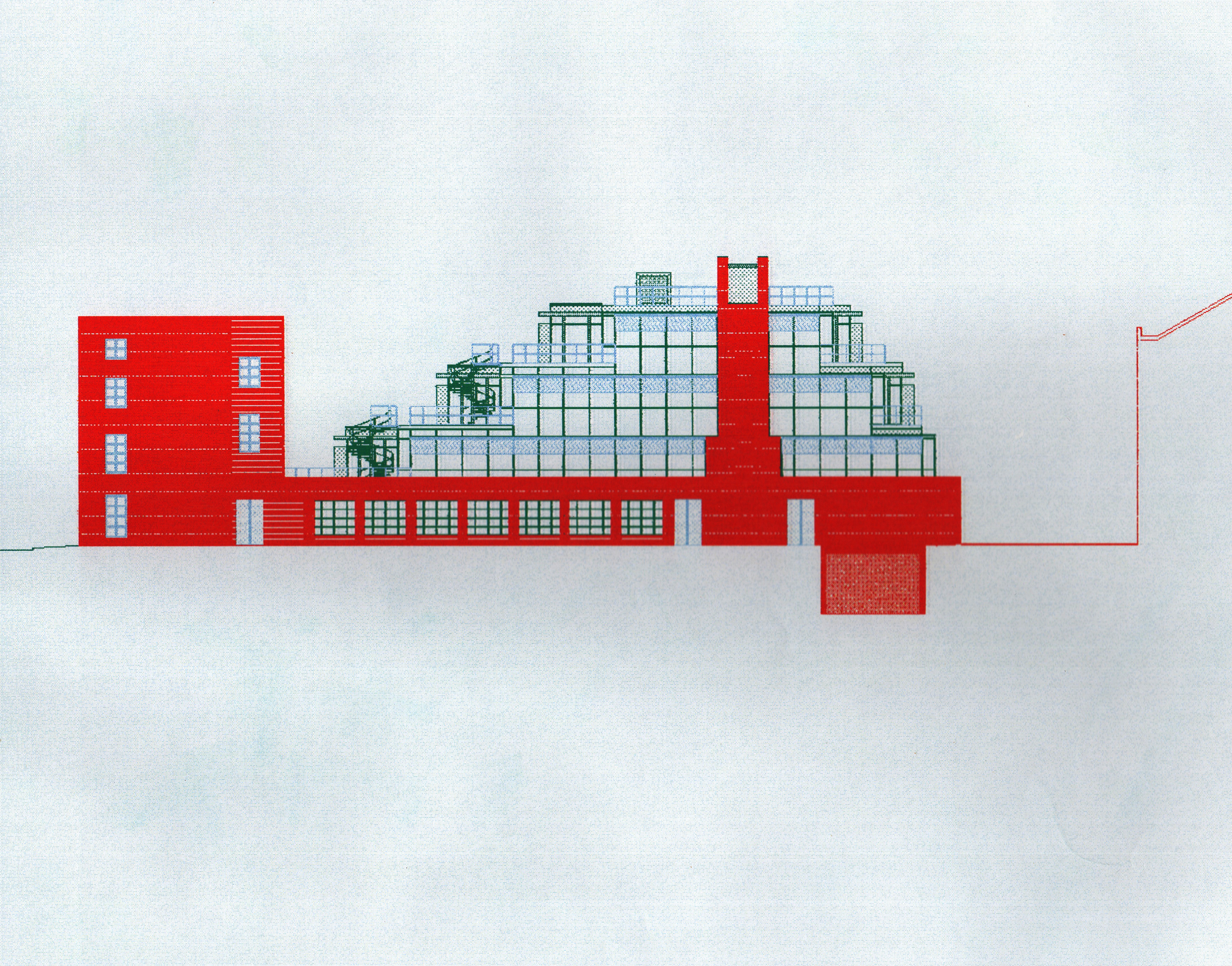
Figure 14: South Elevation
The existing buildings (to be renovated) were owned by the developer and planned to be occupied by tenants of the development. Privacy issues between these buildings were not an issue for these previously residential terrace homes. (Drawing by John Millard)
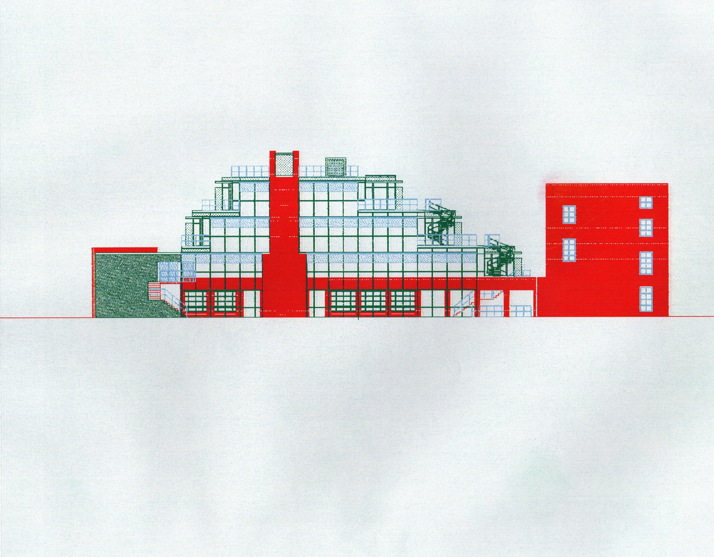
Figure 15: North Elevation
The North Elevation shares a common exterior with a passageway that serves as a pedestrian access/ egress to and from the north.
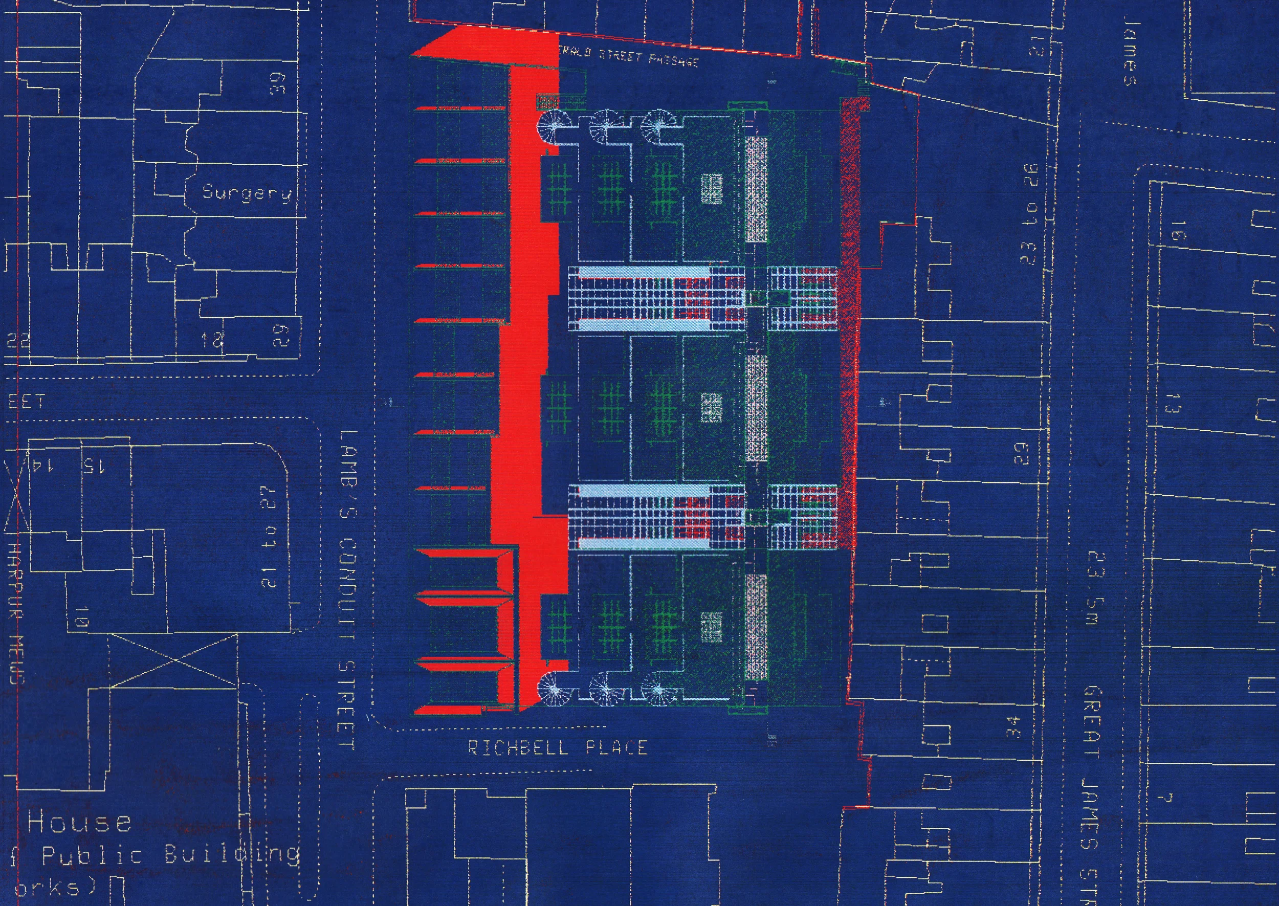
Figure 16: Screen Dump from GDS Terminal
Arup trained John Millard to use the software by McDonell Douglas Information Systems to import Ordinance Survey Maps into he drawing environment and produce accurate site plans, sections and elevations of the project in 1989.

