London Underground- Jubilee Line Extension Station: North Greenwich
Project Summary:
Architecture Firm: Allsop & Partners/ London Underground Jubilee Line Components Design Team
Client: London Underground
Date of Construction Completion: Oct. 2000
John Millard's Role: Component Design for Services Distribution System and Architectural Metal Balustrades
Date of Design Effort Complete: Schematic Design- April 1995, Design Development- May June 1995, Construction Documentation- Sept. 1995
London Underground planned for the extension of the Jubillee Line Underground Service over several decades starting in the 1970s. The technology of tunnel boring machines had been tested with the Channel Tunnel in the 1980s and yet the geology of the London Basin represented a particular challenge to tunnel engineers due to the varying diversity of expansive clay sub-strata. In order to address each type of substrata, a variety of types of tunnel linings were designed for each condition. Segmented Concrete, Cast Iron, Precast Concrete and Cut and Cover tunnels were constructed over various segments of the Jubilee Line Extension. The interior surface of each type of tunnel lining required a different attachment method for suspending neccessary services such as lighting, communications, life safety and fire protection devices. While these attachment methods varied for each tunnel lining condition, London Underground set aside a task for a group of industrial designers known as The London Underground Jubilee Line Extension Components Team led by Roland Paoletti to design a family of components and a system of services distribution that would be interchangeable from one station to another. Additionally, these components would be be durable with a 50 year design life.
The London Underground Jubilee Line Extension Components Team was a group of approximately 12 designers whose task of delivering schedule information, safety for travelers, sufficient amounts of lighting, emergency alarms, seating, refuse receptacles, ticketing gates, variable information displays, public address speakers, closed circuit tv cameras, and a method of delivering power and communications to all of those components- was defined by a system requirements specification written by London Underground's transportation engineers and public health and safety directorate. Interpreting this document and preparing proposals for approval in order manufacture prototype components for each one of these services was a process that spawned a dialogue between departments of this organization that was cumbersome to obtain approvals. Roland Paoletti, the architect who worked with Le Corbusier was hired with the purpose of assuring that this family of components was designed on budget and on schedule, but also that these components were beautiful and aesthetically formed a family of related objects so that lights, speakers, signage, gates, benches, balustrades, etc. all looked like they belonged together in the same underground network.
The first task in defining this family of objects was to develope a standardized cable tray solution that would carry both AC and DC electricity of varying voltages, CAT V data cables, fire alarm cable, coaxial cable, fibre optic cable and telephone cable. This purpose built cable tray would be extruded with compartments that carried each of these services to their intended appliances. The delivery of power and communications was not all that this cable tray would perform, it would also act as a component hub that enabled speakers, or cameras or lights or displays to be plugged in to this cable tray that was to be suspended from the tunnel linings in the plain sight of all who travelled on the Underground. The components team would develop methods of coupling these extrusions together in such a way that opportunities to "plug in" would be created at each coupling, and the cable tray itself would be split into two "wings" that formed a gap betwixt the two wings in order to create a multi purpose component bay that continuously offered opportunities for light, sight, sound and information to be displayed. The design of this cable tray evolved beyond that descriptor and it was soon call a "Selective Services Distribution System" otherwise known as "The Boom".
The boom was going to become a ubiquitous sight within the London Underground Network of rail platforms, passenger access tunnels, escalator halls and concourses/ ticketing halls- not just on the Jubilee Line, but system wide, a solution to the growing need for cameras, public address and other safety features was needed. The components team was recognized as having produced a strong concept for The Boom by the engineers and standards inspectors who reviewed the design and so permission to manufacture prototypes of The Boom was given and work was started on the extrusion of the prototype Boom. The cost of creating a dye to produce the extrusion was mitigated by the "two wing" design, enabling the dye to be smaller- but each wing had a different cross section so there had to be two dyes made, one for each wing. Cable fill calculations were complex because The Boom was not a ventilated cable tray. It required washing periodically and so the cable fill calculation was determined to be a conduit calculation and not a ventilated cable tray. The tunnels in the London Underground are periodically thoroughly pressure washed. Electrical enclosures have to be rated for pressure washing- and so the Boom was determined to be a washable enclosure, the equivalent of somewhere between a NEMA 3R and a NEMA 4 enclosure in the USA.
Once the cable fill calculations and the access requirements to these Booms were determined, the method of transitioning from one segment or extrustion to another, through a coupling with a series of appropriately sized nipples was designed. These couplings were also one of the locations where a service opportunity could occur as described above. The location was between the wings of The Boom. The team cleverly designed what are known in England as "Halfen Channels" into the extrusion so that brackets could be designed to randomly snap and slide into any location along the Boom in order to site the lighting bracket of CCTV bracket into the desired position. These brackets were known as "component brackets" since they were dedicated to suspending brackets between the wings of the boom. The Boom Brackets were brackets that captured the ends of the extrusions and also allowed the cables to pass continuously in their nipples from one segment of Boom Wing to the next. These Boom brackets were the point of suspension of the Boom segment where aircraft rod with swaged stainless steel fittings are bolted to the bracket at one end and to the tunnel lining at the other.
The aircraft rod were extremely expensive but the quantities that were required for the London Underground were sufficiently large economic order quantities that the team was able to make a strong case for these to be purchased by the contractor who would install the SSDS. The benefit of the aircraft rod was that it was telescopic in length. This vastly reduced the complexity of the attachment method by enabling multiples of 6" rods to be ordered and the telescopic tolerance of the rod would accommodate precisely the desired length in situ. What that rod attached to depended on the type of tunnel lining as was described at the outset. Whether this attachment turned out to be a through-bolted condition or a resin-epoxy anchor shot into segmented concrete was now a definable coordination exercise and not dictating the design of the SSDS based on the type of tunnel lining or the structure that attaches to it.
The role that John Millard had on the team was to design bracketry that would be compatible with the pre-existing family of components which to date included The Boom, The Component Bracket and the Boom Brackets. Therefore the basis of design was established by these components and John Millard designed the lighting bracket, the CCTV bracket, the variable information display bracket, the speaker bracket and the signage brackets for the SSDS. These brackets were designed using 3d Studio, MicroStation and Autocad with some use of Micro-GDS.

JLE North Greenwich Station- egress stair vertical pano
Photo taken in Nov. 2019 by John Millard shows smoke hood designed to evacuate smoke from burning train. Hood also transports selective services for distribution along the entire station. CCTV, Variable Information Display, Public Audio, Power, Communications and Fire Fighting Appliances are baked in. Design by Will Alsop. JBM designed glass balustrade bracketry details for this station. Which was fun.
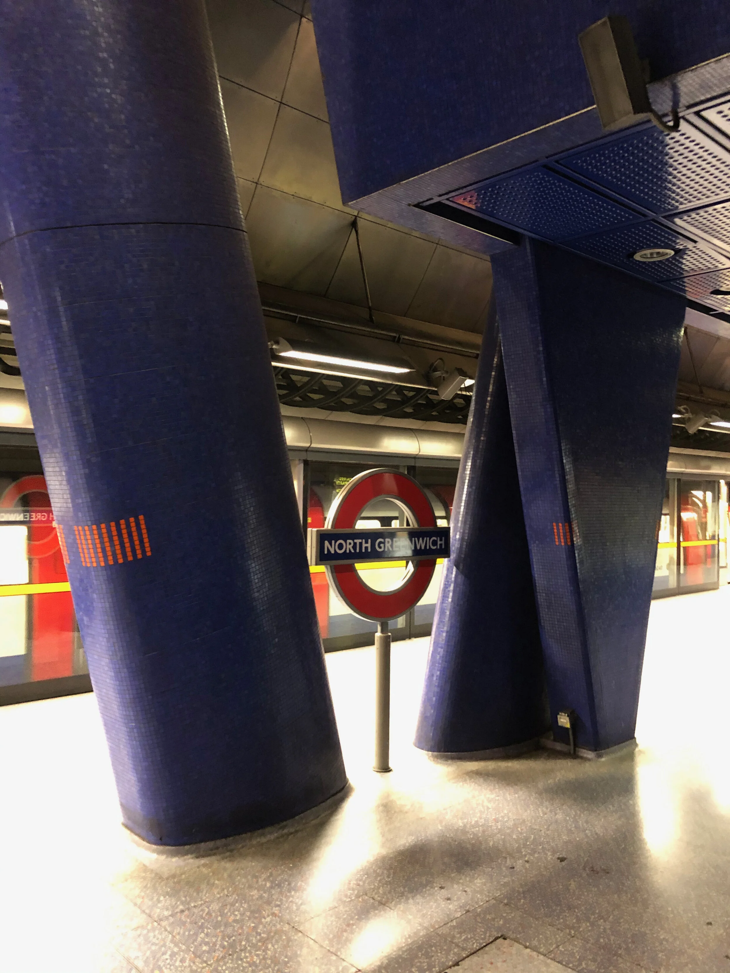
JLE North Greenwich Station- Mezzanine Pier
The Mezzanine Piers shared footings that were expensive steel reinforced concrete islands in the London Clay. The ceramic casings are driven from clay. London Underground has a long heritage of ceramic wall and floor coverings in station design.
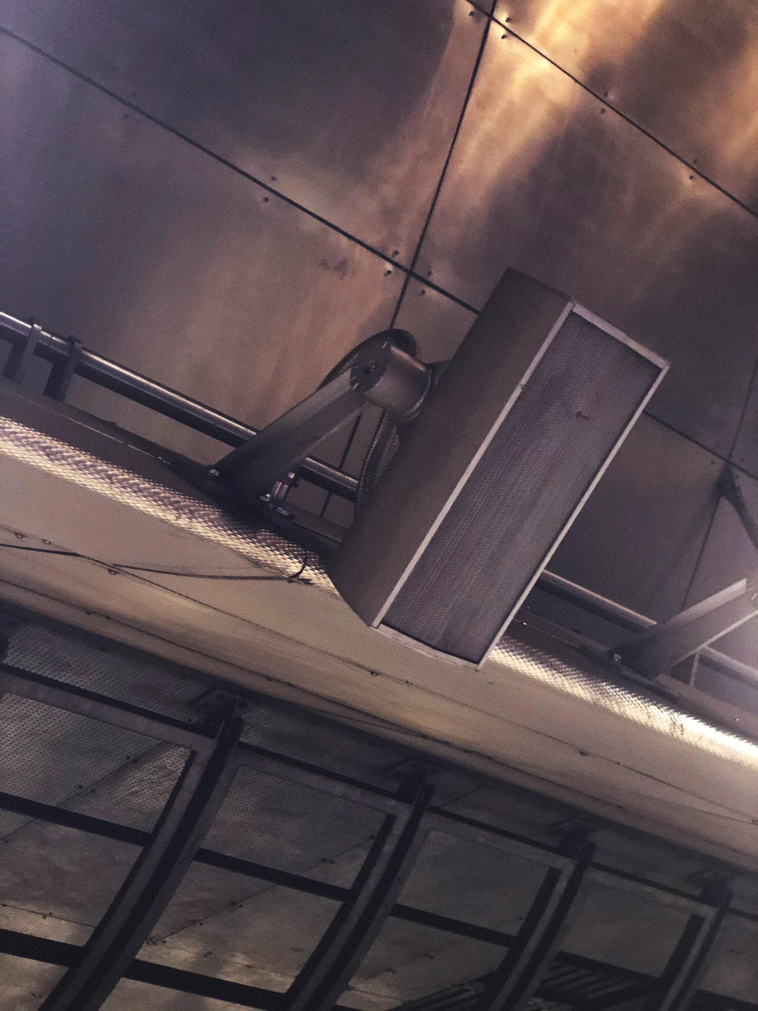
JLE Station North Greenwich- Public Audio Bracketry
The Speaker Bracket is similar to the other brackets in the twelve other stations, Based on a lost wax casting of a t-flange, it it a family of t-flanges that support the various devices that populate the Jubilee Line Extension.
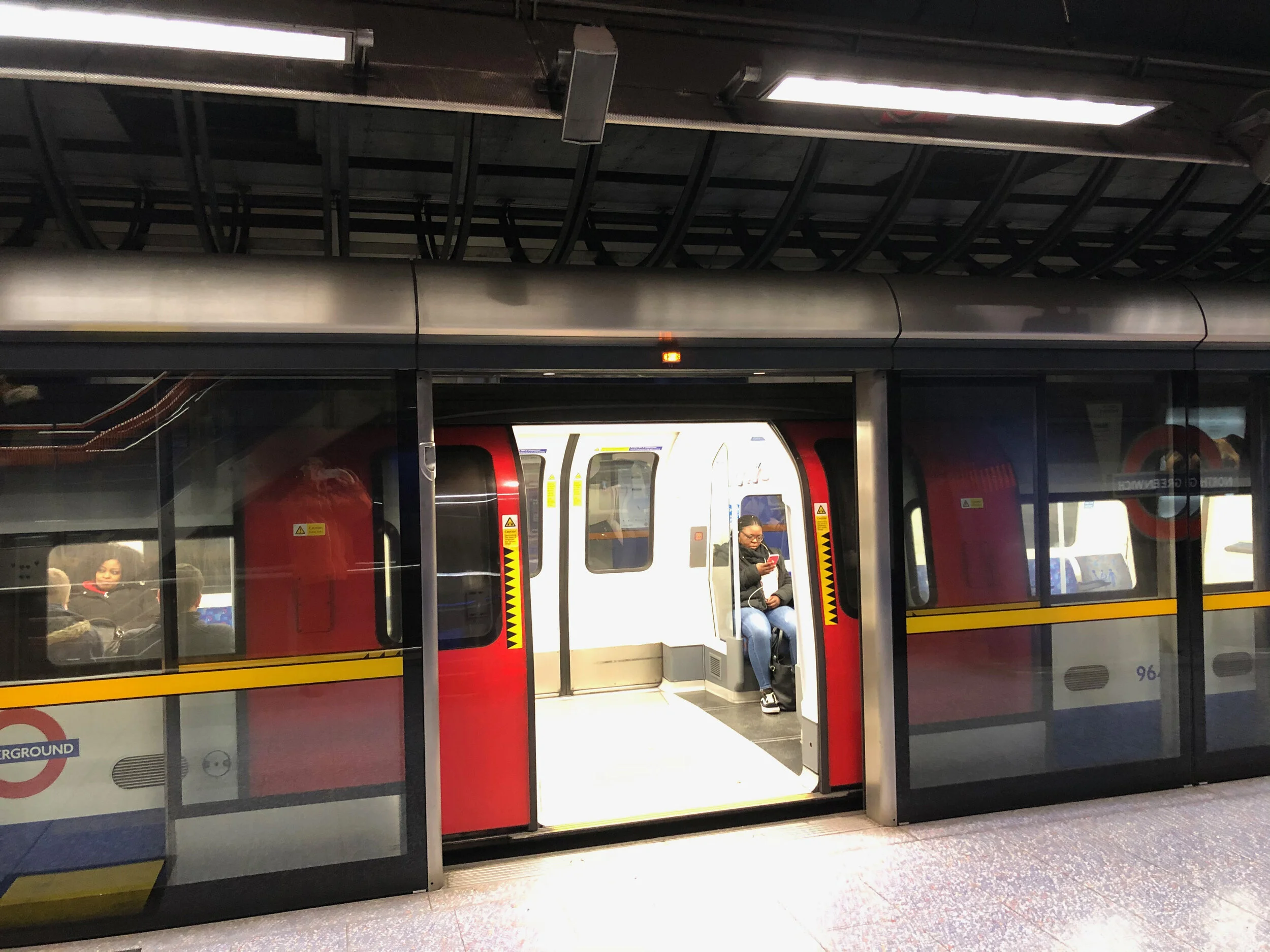
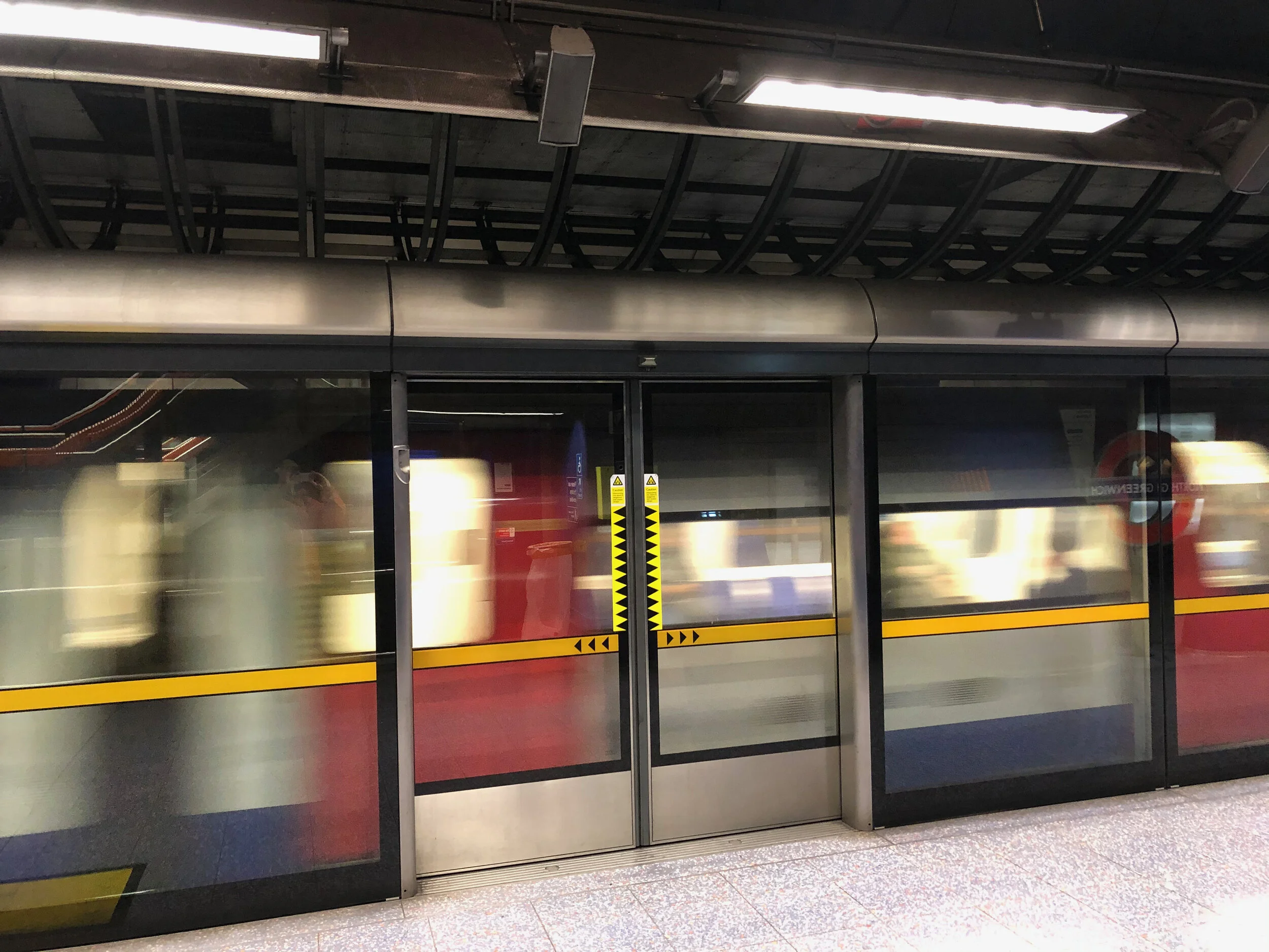
JLE Platforms Add Safety with Pedestrian Fall Protection Barriers
London Underground has for over one hundred years provided platforms to its stations that compare with most of the world’s subway stations in that they have required the pedestrians to stand away from the edge of the platform prior to accessing the train. The Jubilee Line Platforms are the first in London to provide fall protection for pedestrians.

Egress Stair to Mezzanine
In addition to the extensive escalators in Greenwich Station, the design also called for egress stairs from the platform to the mezzanine above where pedestrians can make their way to the surface from this cut and cover station that lies approximately 30 meters beneath grade.
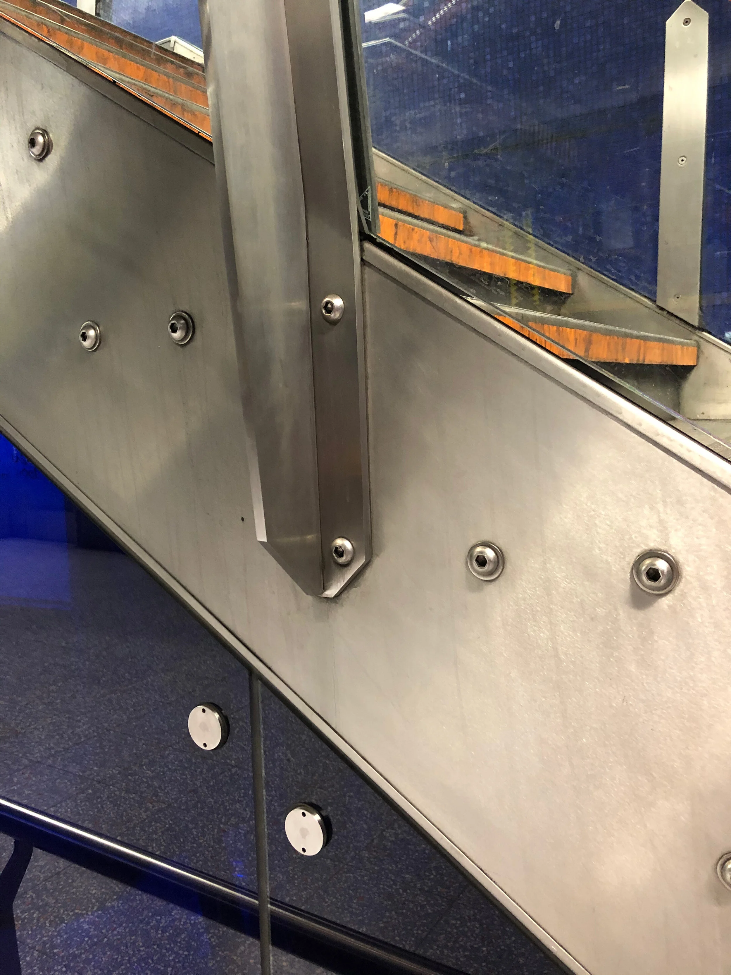
Architectural Metal Balustrade for Egress Stair at Greenwich Station
The original design for the balustrade was a lost wax casting design but the value engineered version that was constructed was a stainless steel fabrication that approximated the the original design.

London Underground- Jubilee Line
Conceptual animation showing components designed by John Millard using freehand sketching and 3d Studio R3 by Autodesk in 1995.

Stainless Steel Balustrade with Fritted Armourplate Glass Spandrels at Mezzanine Level
The constructed balustrade has supports that cantilever off of the mezzanine and lean out over the void. The Blue Glass backdrop of the 30m retaining walls recede into the background where escalators unite the levels with diving forms of stainless steel and fluid movement of people.
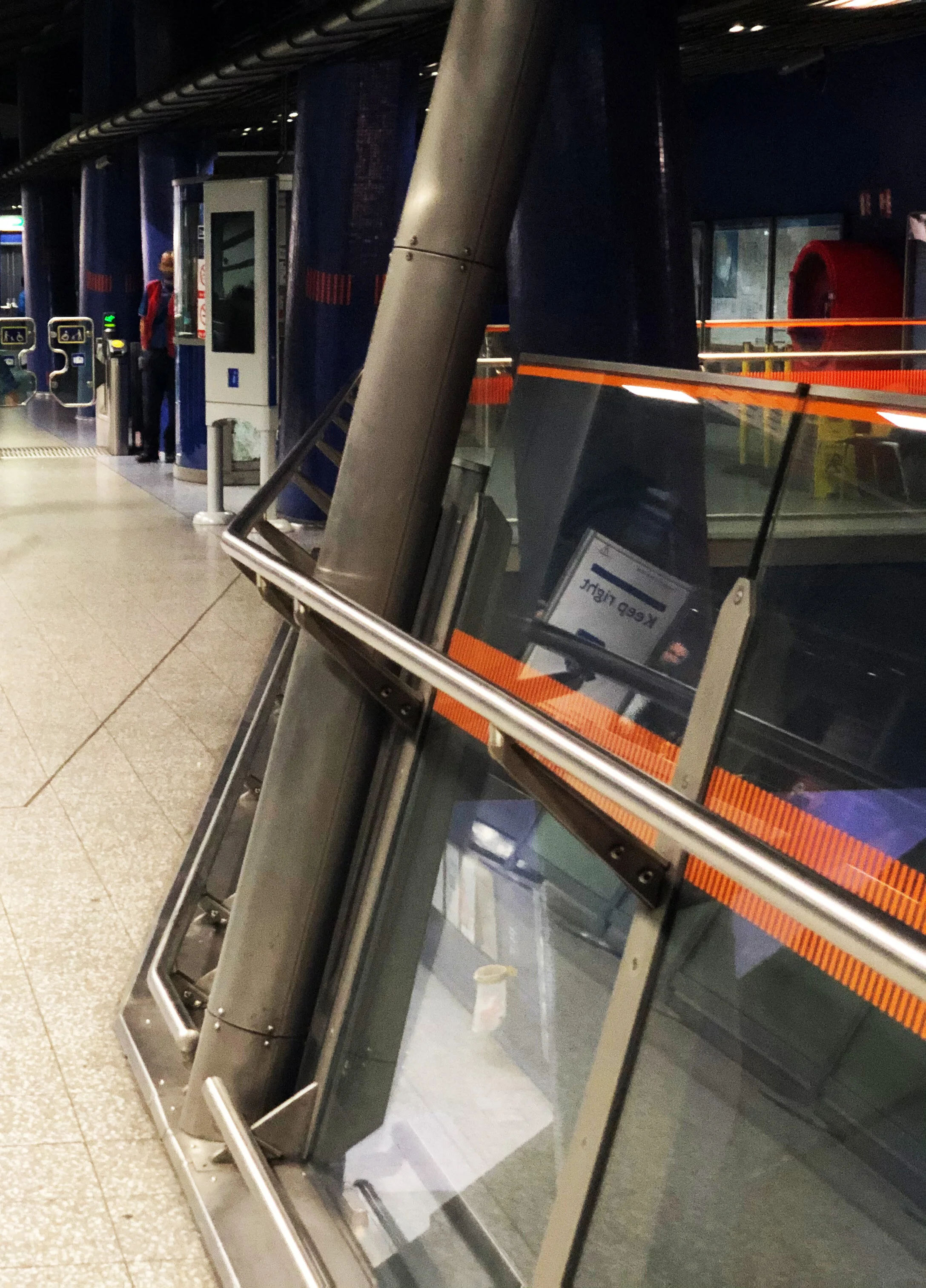
Metalwork of the Balustrade Captures and Clamps the Sloping Armor-plate Glass Spandrels
The lead designer of the North Greenwich Station was Will Allsop, the Pritzker Prize winning architect that followed through all of his buildings with a characteristic art. The buildings he designed are invested with curiosity and care that drills down into the smallest details and direction that materials lead the eye with.
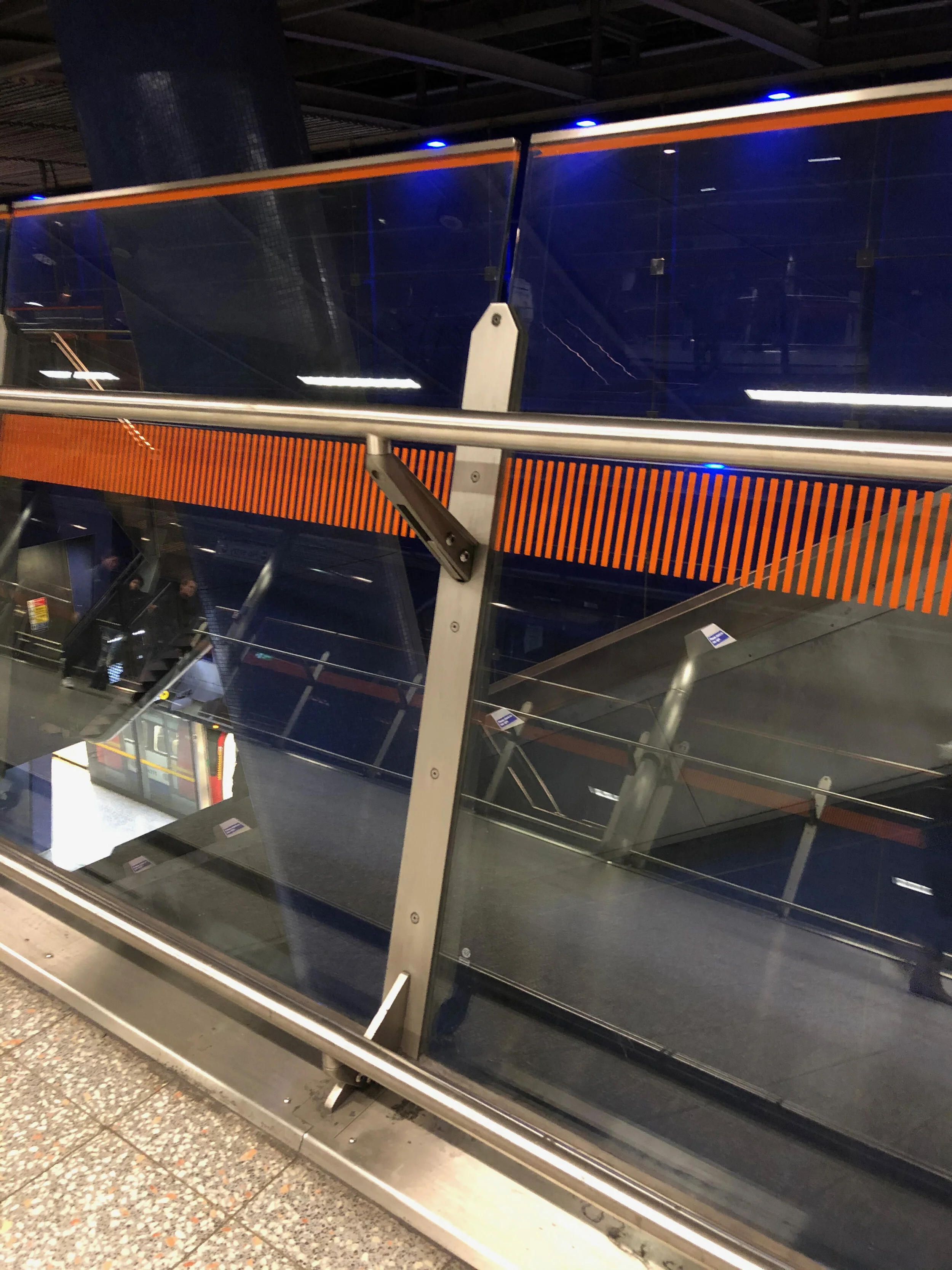
Foot Rail Detail in Stainless Steel with Floor Edge and Closure with Glass
The edge of the Mezzanine oversails the platforms 30m below. In order to defend against debris from falling from the mezzanine, a footrail detail that provides for an embedment to anchor the balustrade post into the concrete is hidden by a continuous stainless steel cover.

Combination of Lost Wast Casting and Stainless Steel Fabrication Results in an Elegant Handrail Bracket
Here in this photo, the final constructed detail showing the handrail as a hybrid assembly of cast alloy with stainless steel plate, sandwiched together in an assembly of components that form a strong connection to the welded flange of the off-vertical post.
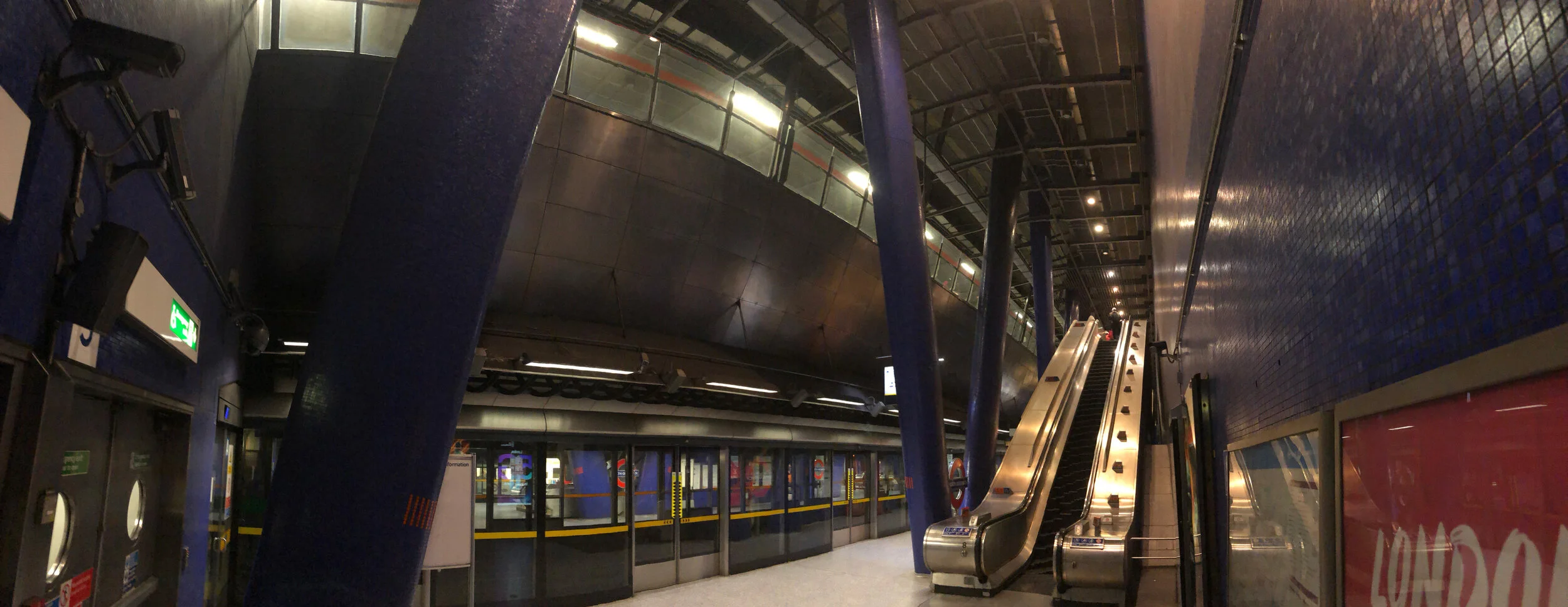
Panorama of Greenwich Station Platform and Mezzanine Above
The glass balustrade can be seen cantilevering over the platform from the Mezzanine above. Allsop & Partners designed the station in 1993 and incorporated the twin canted columns characteristic of their work.

Beneath The Surface of the Earth, London Underground's North Greenwich Station Mezzanine
The forest of splayed, sloping columns that support the surface of the street above carry the mezzanine of the station superstructure. This promenade of people carries them to the final flight up to the street.
