103KW Solar Project for New Jersey Housing and Mortgage Finance Administration
Project Data
End-User: New Jersey Housing and Mortgage Finance Administration
Installer: Evco Mechanical
Location: Trenton, New Jersey
Date of install: July 2007
Size of system in kW: 103kW
Energy produced since installation~500MWh
Special Challenges Met:
Project Brief:
Turnkey Delivery & Installation of a 103kW Photovoltaic System
• Guaranteed Power Capacity (103.01kW), measured at the inverter(s) input.
• Guaranteed Power Capacity (87.39kW), measured at the inverter(s) output.
• Estimated Capacity Factor (12.85%) and annual output (125,997kWh)
• Guaranteed PV Panel Degradation rate for 20 years (10%)
• PV Array Materials- Multi-Crystalline Silicon encapsulated in lead-free glass with biodegradable encapsulant (enables disposal in land fill rather than toxic waste),
Here are some other attributes of the PV Module (also see spec sheet). Greatest Power of Any Module Fewest mounting fasteners and external electrical connections per watt of array. High Efficiency Silicon Solar Cells High power per unit area in a long life, stable crystalline solar cell. High Module Voltage Allows integrators to “fine tune” the system by providing just the right number of modules to meet the specified power… Perfect for grid-connected and high voltage battery systems. Advanced Encapsulant Developed by RWE SCHOTT Solar, this encapsulation system has been shown to outperform traditional EVA. Double Glass Construction As a perfect moisture barrier, the glass-on-glass construction provides the longest possible module life. Internal Bypass Diode Protection Bypass diode protection every 18 cells in series. No-Lead Solder Modules are safe for disposal in any ordinary landfill. Quick, Polarized Connectors Array module-to-module wiring can be a snap Flex Interface System Enables wide range of interconnection options that can be tailored to the customer’s needs. Power Testing at the Connector Wire loss within the module to module wiring is already accounted for at the factory module tester. IEC 61215 Certified An international independent certification of module performance. UL 1703 Listing A world recognized authority on electrical safety… Makes approval a breeze. Class A Fire Rating Permits module mounting on any roof with no compromise in the roof’s fire rating. • Inverter: Satcon 100kW utility interactive inverter (most efficient inverter on the California Energy Commission eligible inverter list). • Structural Materials (see illustrations below) Entire Array is set at a fixed 5 degree tilt on a steel superstructure which has minimal penetrations through the roof (28 steel piers). Modules overhang the skylight, providing full winter sun penetration through skylights and allowing noontime shading to reduce heat gain in summer. Existing sloping roof has 3” of rigid insulation- this disallows conventional pv mounting hardware solutions, such as unirac or pro solar mounting rails due to shaft length of fasteners. Also, metal decking is inappropriate substrate to affix to due to thinness. TurtleEnergy TurtlEnergy LLC Linden Voice Fax Web Email 1900 Lower Road, New Jersey, 07036 908 397 5740 732 292 9491 www.TurtlEnergy.us John.Millard@TurtlEnergy.us 3’6” Steel Superstructure attaches to the existing structural trusses at their strongest point- the ridge beam. The Trusses occur 21’ on center, there are two penetrations at each truss, one on each ridge. (Trusses not shown for clarity.) 103kW PV Array overhangs ridges by 3’-6”. Summer high noon sun is shaded from the Callwall translucent panels but allows direct sun heating in the winter when the sun is lower. SUMMER SUN 45 Degrees WINTER SUN 25 Degrees The Schott Solar Panels are built with a structural aluminum extrusion as a frame which is designed to span the length of the Module on special supports for commercial pv systems. This frame carries the weight of the module from specially designed mounting pins which in this case, are locked into a bracket which is bolted to the structural metal (and not to a secondary racking system commonly found in residential pv applications) Mounting Pins Mounting Brackets TurtleEnergy TurtlEnergy LLC Linden Voice Fax Web Email 1900 Lower Road, New Jersey, 07036 908 397 5740 732 292 9491 www.TurtlEnergy.us John.Millard@TurtlEnergy.us (3.8.1 Continued) • Balance of system components: see attached specifications sheets • Configuation: including flat and tilt mounted systems: see above illustrations • Structural requirements: see above narrative • Operation and maintenance: the system is self cleaning due to the washing action of the rain over the 5 degree angle of the mounting structure. The monitoring system enables for periodic system checks from the desktop. Installation warrantee in New Jersey is for 5 years. • Typical Degradation (by Warrantee) is ½% / year. • Benefits specific to this system: see attached document on next page.
Letter from Installing Contractor to TurtleEnergy after persistent Inverter Problems were determined to be the cause of an electrical ground fault (that had been previously thought to be a wiring fault in the array).
" RE: SatCon Inverter Location: New Jersey Housing Mortgage Finance Agency Building- As you are aware, the SatCon.l00kW inverter installed at the New Jersey Housing and Mortgage Finance Agency has experienced numerous shutdown events since if was commissioned on November 20, 2008. Some of these shutdown events have been related to field conditions (e.g., ground faults) that were corrected, others have been the result of an, as yet, undiagnosed issue. When the inverter was first delivered, it had a number of defects that indicated the unit had never been factory tested under load (e.g., an improperly wired terminal block; a faulty contact in the DC disconnect switch; loose connections on the main control board; etc.). There were also problems with several of the PV panels (e.g., cracks, bad diode packs, etc.). The aforementioned problems were diagnosed and (apparently) repaired by Turtle Energy's representatives at the time of installation and during subsequent troubleshooting forays. And, because the problems were handled expediently and with exemplary care and concern, we (Evco Mechanical) decided to accept the equipment as is, and made our payment in good faith. However, it is now clear that something is still wrong at the site, and we implore each and every party involved in the design, installation and commissioning of this system to help us address this problem immediately. This is a sho'wease installation; it 'will generate more business for all involved. Vie cailiiot treat this as if it were a problem with just any array. This site is front-and-center with the Governor's (and many other state offi.cials) office(s). It would ill-behoove us all to neglect this issue. We respectfully request a plan of action from each of you as soon as possible. Thank you for your help. "

Photo 1: Panorama from Northwest showing the 103 kW Tilt Rack tied into existing building steel.
New Jersey Housing Mortgage Finance Administration (NJHMFA) required a solar PV system on the roof of its headquarters in Trenton, NJ. The opportunity to retrofit a steel grillage above one of the original building's roof monitors became the design strategy early on in the project.

Figure 2: Axonometric showing building mass and (right) photo of roof from above with superimposed solar proposal.

Photo 3: Interior of HMFA showing steel roof structure (above) and Kallwall window replacement system from renovation of earlier years.

Photo 4: Exterior view of roof structure with Completed 103 kW Solar Installed in 2009

Figure 5: Conceptual Sketch showing proposal by John Millard indicating method of attachment and orientation of solar array using Schott ASE-300 320W Solar Modules

Photo 6: Photo showing assembly of brackets and beams used to attached the solar modules to the superstructure. This attachment method used manufacturer's mounting pins supplied with the equipment.

Figure 7: Sketch showing bracket as proposed by JM.

Photo 8: Cantilevering beams carried solar modules past the support beams and out over the Kallwall enclosure in order to reduce summertime solar radiation inside the air-conditioned space.

Figure 9: Conceptual Sketch by JM showing attributes of passive cooling of the solar array as well as the clean electricity generation provided by the photovoltaics.

Photo 10: Ironworkers Union Operatives assembled the steel frame, Electrical Workers Union operatives installed the solar modules and electrical system.

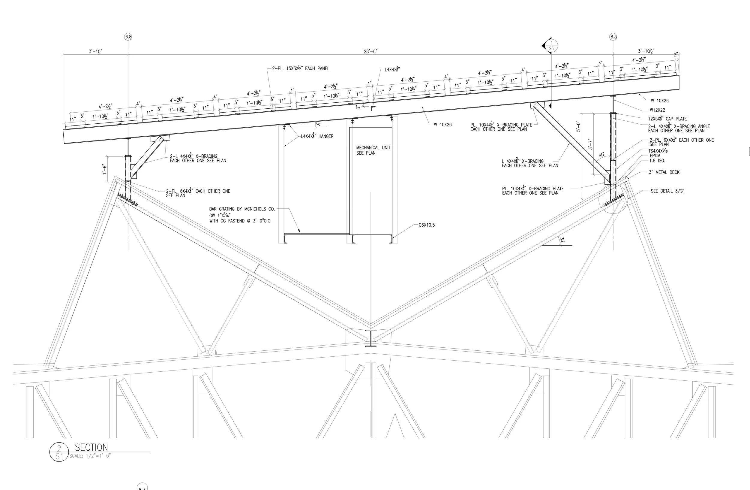
Figure 11: Structural Engineer's Section showing beam and fitting sizes required to achieve the 23' span.

Photo 12: View under the span showing cable tray as the dc electrical distribution method.

Figure 13: Structural Engineer's attachment detail for solar support structure.

Figure 14: Inverter Platform- The Structural Engineer (pictured here facing us) provided a high degree of service on site as well as from behind his slide rule...

Figure 15: Structural Engineer's Framing Plan: this steel canopy was 100% galvanized.

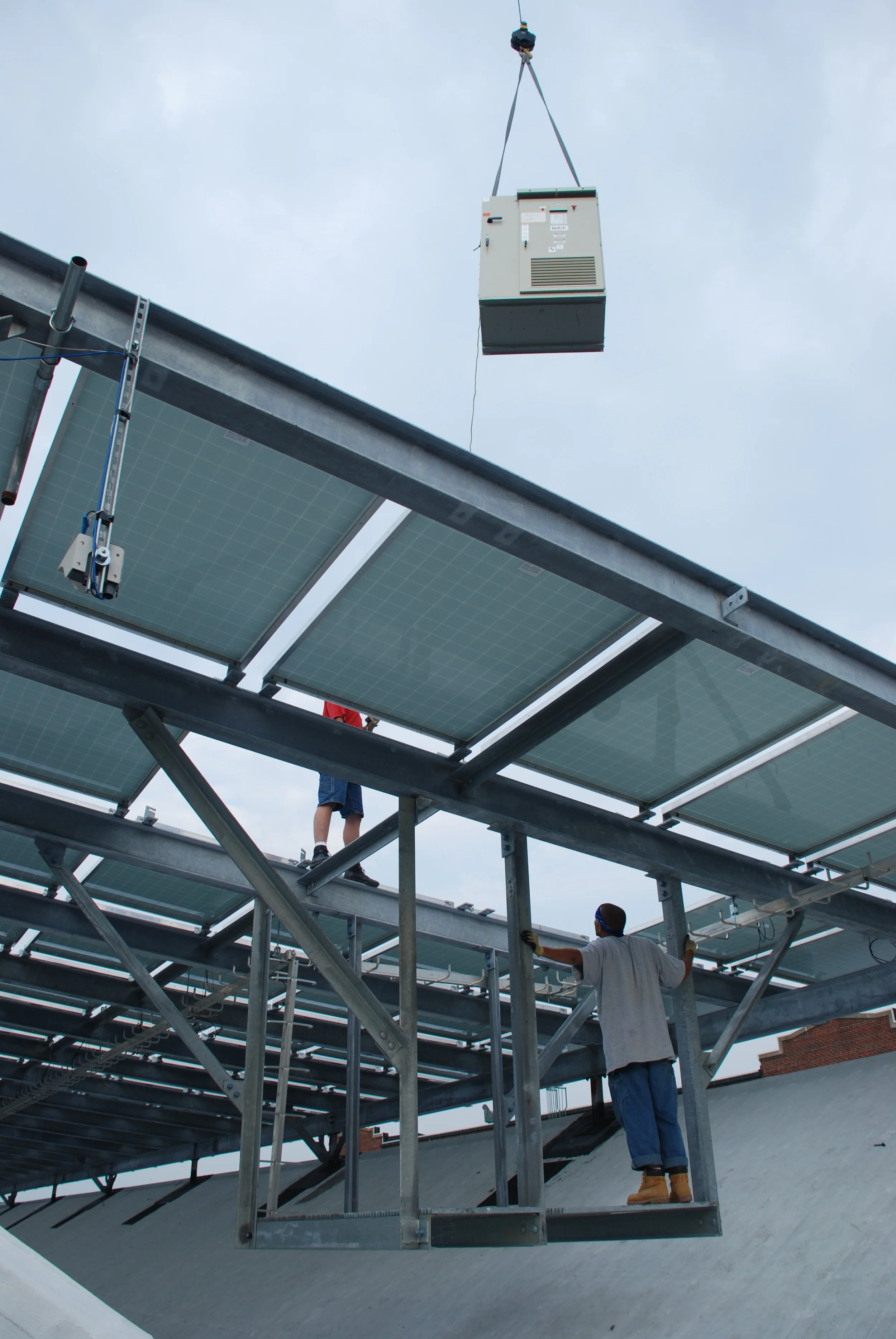
Figure 16: Inverter Rigging went through temporarily vacant module locations, then placed on the platform.

Figure 17: Structural Penetrations in the Roof Monitor were made water tight after opening up the roof and constructing the structural detail shown above (Drawing by Structural Engineer)

Figure 18: Weight of Inverter- about 3600 lbs.

Figure 19: Suspending the 3600 lb. Inverter above the roof allowed for good, close electrical adjacency of the dc circuitry.

Figure 20: The Inverter was sited without difficulty...
...but the subsequent teething pains from an internal fault in the inverter created a big headache due to perceptions that a ground fault in the array was causing it to trip.

The team from Evco Mechanical and TurtleEnergy had a party down the street in Trenton after this photo was taken.

