Pharmaceutical Pilot Plant for New Drug Development w/ Good Manufacturing Practices- Construction
Summary: JBM was project architect for this project for the entire duration of architectural services from design development to construction document completion.
This Pharmaceutical Pilot Plant was constructed in 2001. The project was led by a construction management team that required an architect to prepare design development documents for approval by the research client during a DD phase which immediately transitioned into a construction documentation phase.
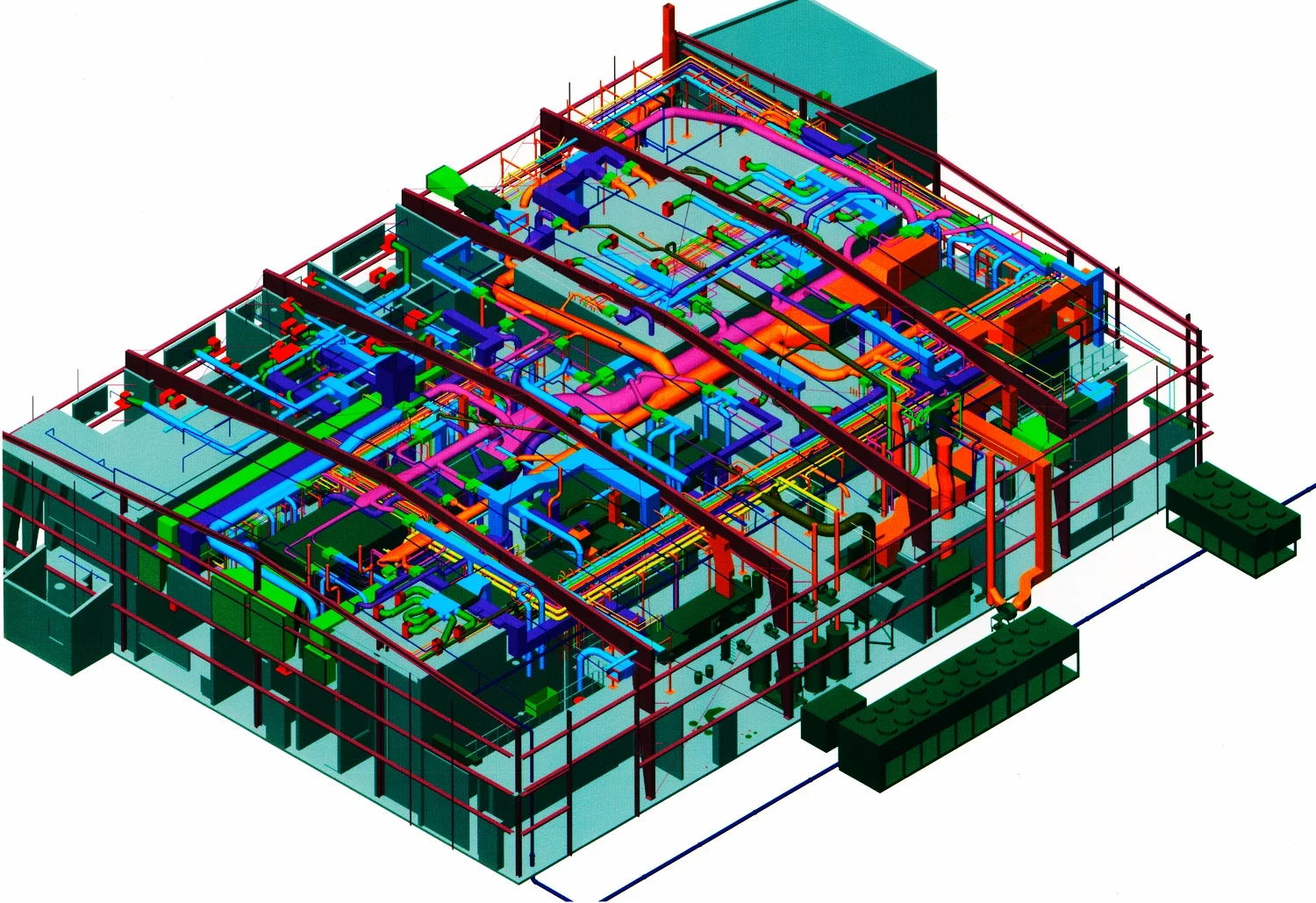
In some of the earliest application of "building information modeling" John Millard embraced the process of predicting with great accuracy the location, quantity, purpose and nature of building elements that have an impact on each of the design disciplines. By closely cooperating with mechanical, electrical, structural and civil engineering team members throughout the process of building a detailed three dimensional model, John was able to incorporate these elements together into a single source of information- a parametric model of the building using Autodesk Architectural Desktop. This program has since been replaced and superseded by Revit.
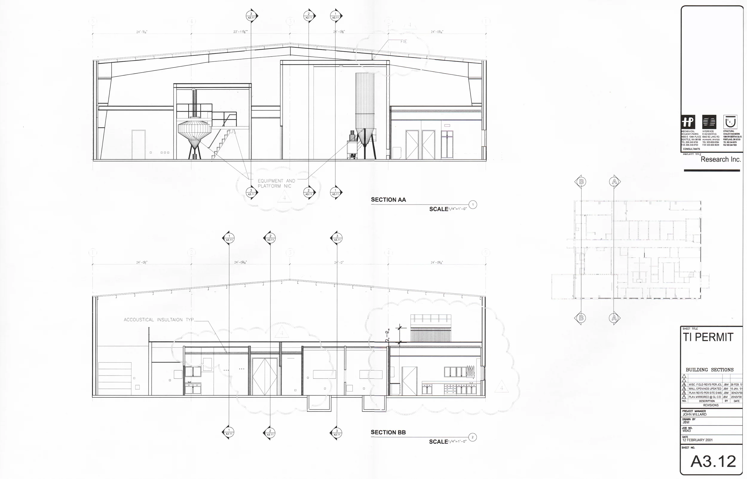
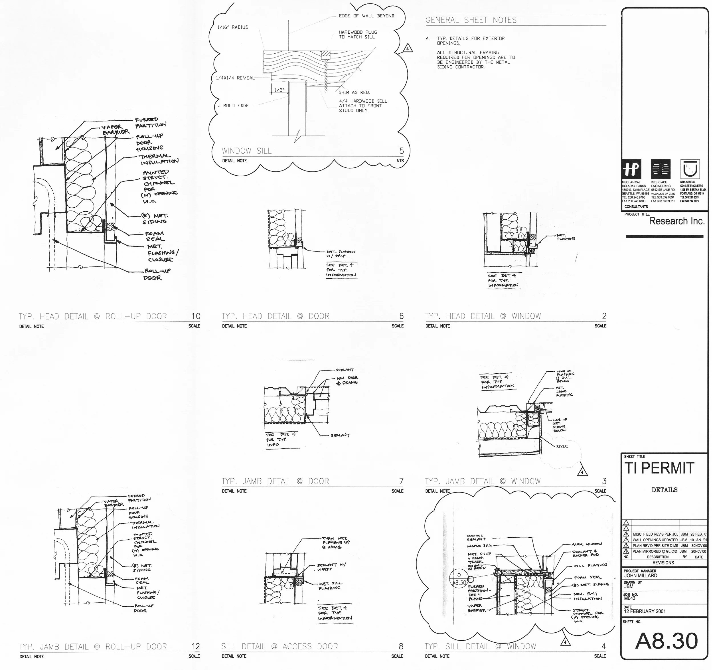
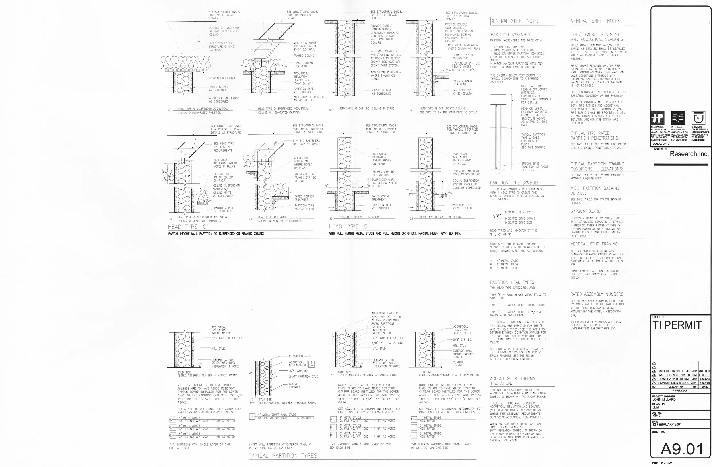
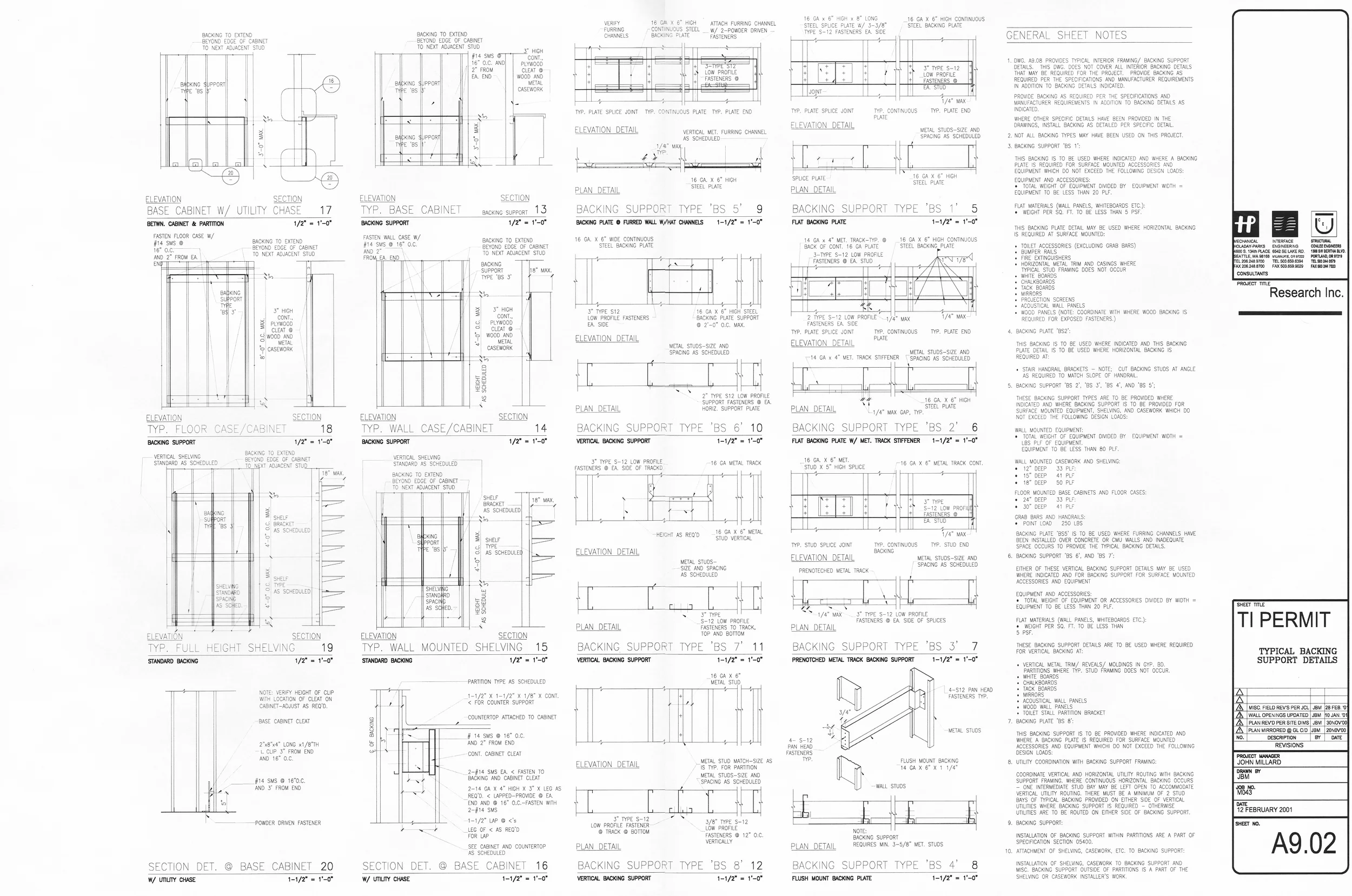
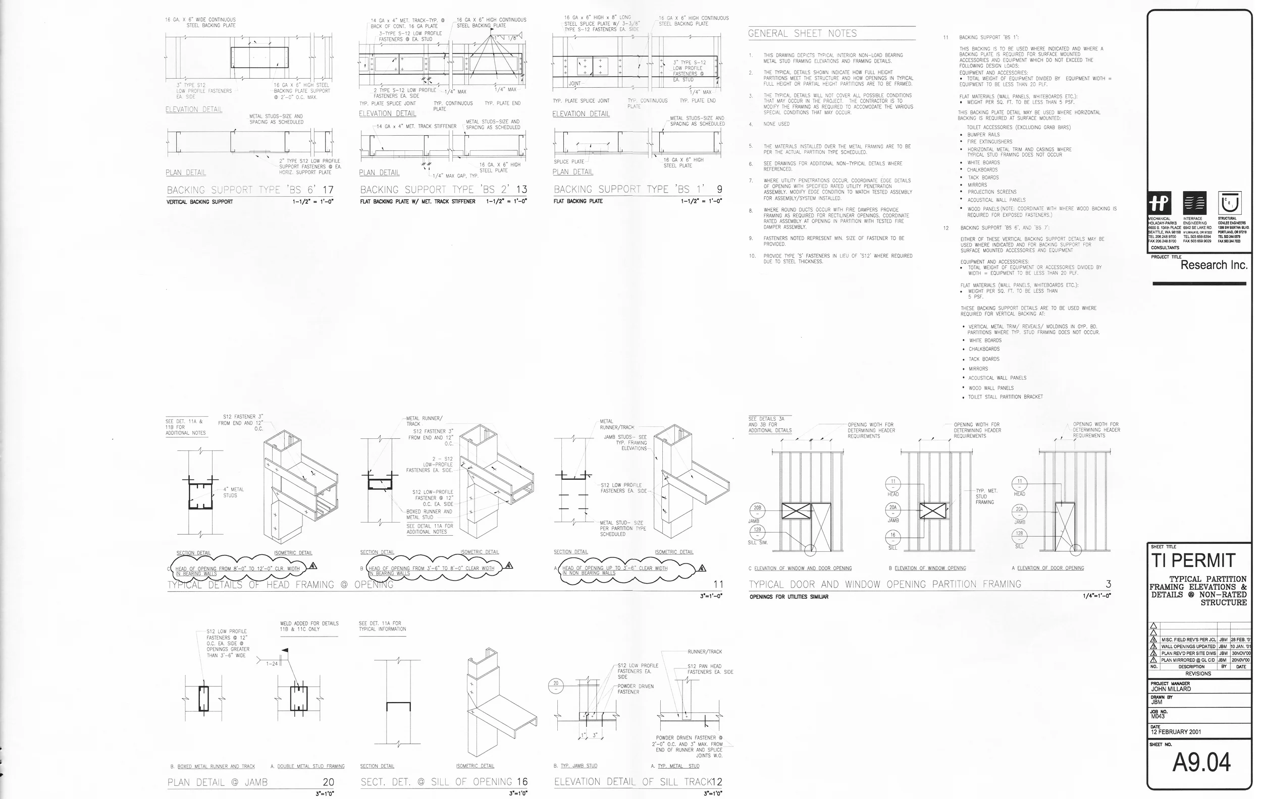
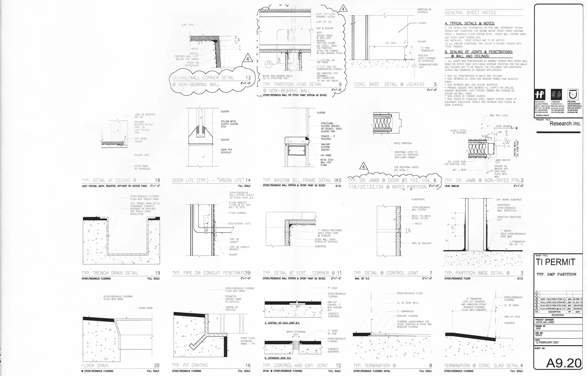
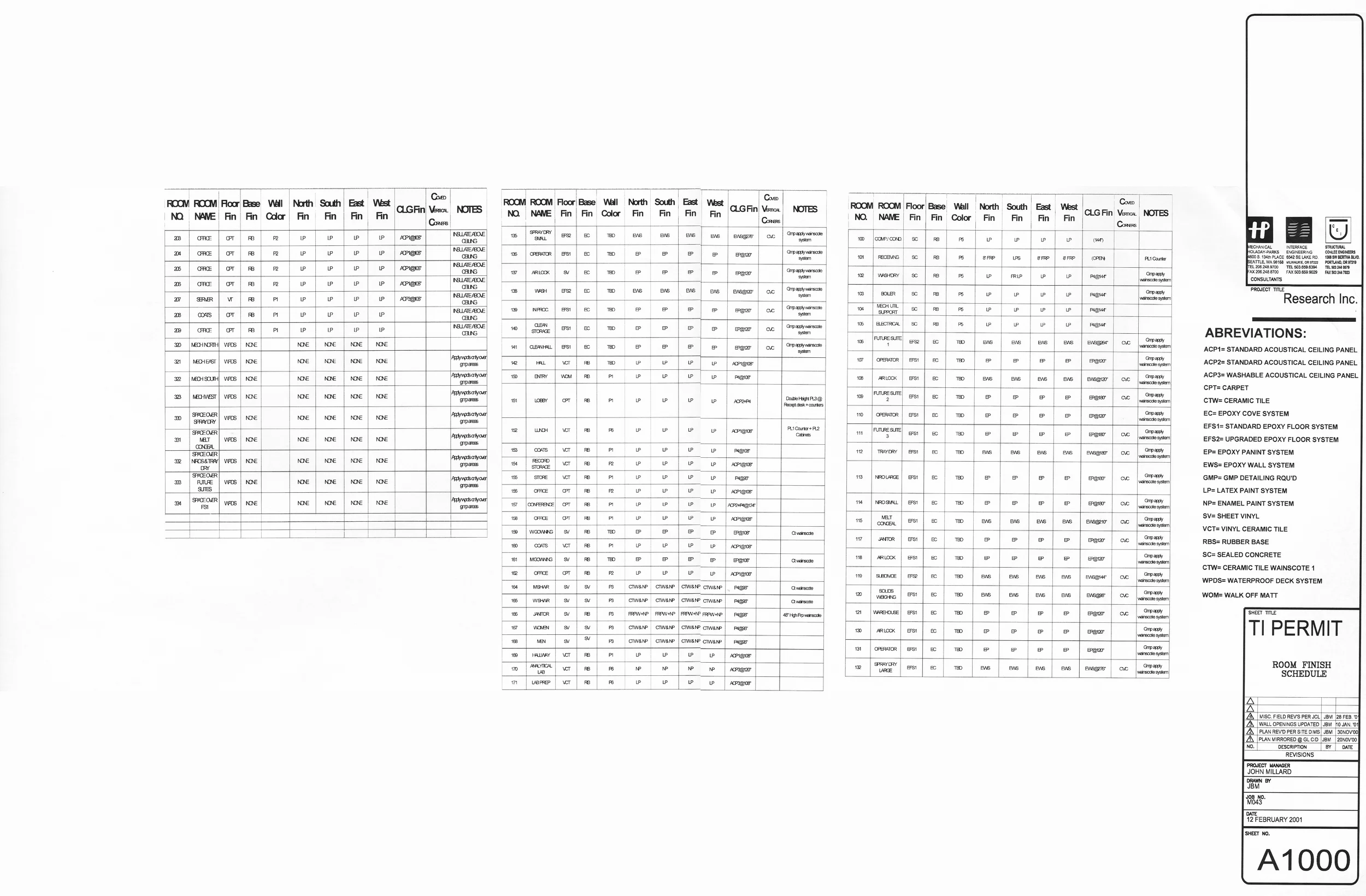
Construction of the Large Spray Dry Space required milestone acquisition by the construction management team, but before these milestones could be achieved, accurate and effective systems required implementation by the design team. Fundamental objectives related to the room size, finishes, lighting, access and egress for fire or other human safety purposes were defined. Then, Good Manufacturing Practices related to the code compliance that exceed normal construction codes were specified. Finally, the systems that support those standards have to be physically accommodated and coordinated within a virtual/ computer model, then clearly printed in two dimensions with traditional construction conventions.
Background:
MBT Architecture was approached by a Pacific North West based construction management company to "be the architect of record" for a pharmaceutical manufacturing plant, otherwise known in the pharma trade as a "powder facility". The lead discipline for the project was the construction management company with the prime contract to construct a "tenant improvement" inside an existing metal building that was inexpensively acquired by the owner and asserted to be fit for the purpose for which they intended to operate inside the building. MBT agreed to a fee to perform the services of documenting a design that was conceptualized by another licensed architect who was a full time employee of the CM firm. Since the CM firm did not possess the manpower necessary to document the design, nor the insurances required to provide architectural services- the scope of work required of MBT Architecture was billed as a single phase construction documentation phase with no construction administration required by the prime contractor.
The Single Phase CD scope of work that became a defacto hybrid Design Development/ Construction Documentation effort (not good process):
The CM-employed architect who provided general arrangement plans to MBT had conferenced these GA plans with the owner of the research facility and obtained approval for those plans to be converted into construction documentation as part of the permit phase of the project. Acceptance of these plans by MBT was understood to be an owner approved document that was not only a functional adjacency diagram, but also encompassed sufficient space in plan and section in order to fit all of the user requirements as well as the additional space required by the mechanical/ electrical team's equipment. As it turned out, the general arrangement plans were very close to the final plans with the exception of a 12" discrepancy caused by a measuring error when the interior clear dimensions of the existing metal building envelope were incorporated into the survey notes by the CM team. This error was reportedly caused by the use of a special civil engineering measuring tape that for some purpose had an additional 12" of tape printed on the end. The measuring team were apparently unaware of the additional 12" to be compensated for when recording their measurements. Unfortunately, this error was not uncovered until construction teams equipped with measuring tapes were verifying measurements in the field in preparation for installation of the first packages of concrete. The 12" discrepancy was reported to the CM and the CM instructed the architect to "find 12 inches" in the 80% construction documents that had been printed and were used to procure initial concrete placement contracts. As it turned out, at this late stage there was no obvious source of wasted space from which the entire building could be shortened and narrowed (both north/ south overall dimensions and east west overall dimensions). It then fell upon MBT to provide a cost to the CM to pay for the design effort that was required to identify sources of space in plan that would be subtracted from in order to make the construction documented design fit inside the erroneously measured existing building.
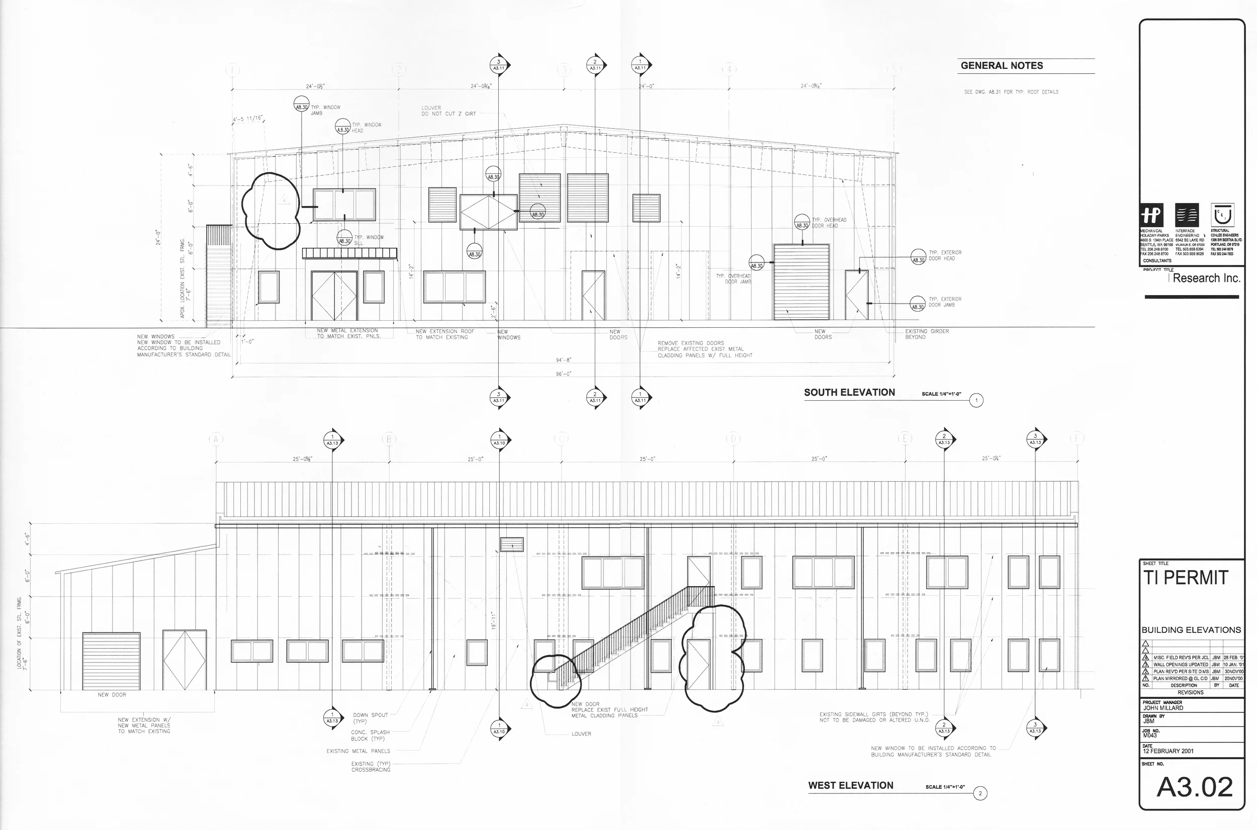
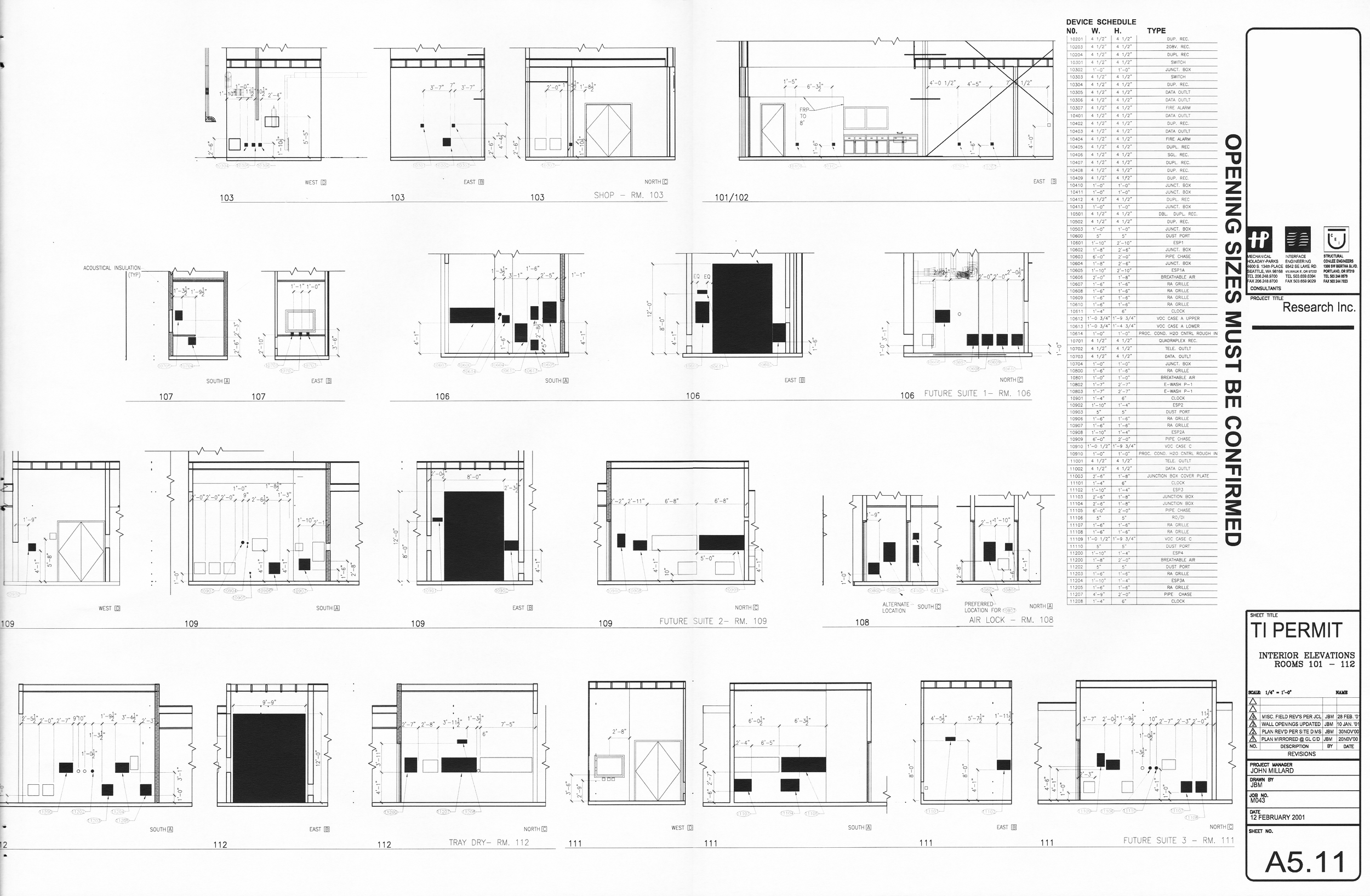
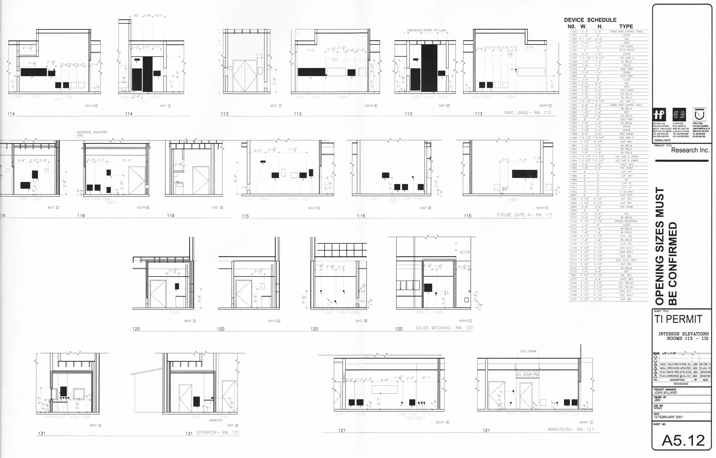
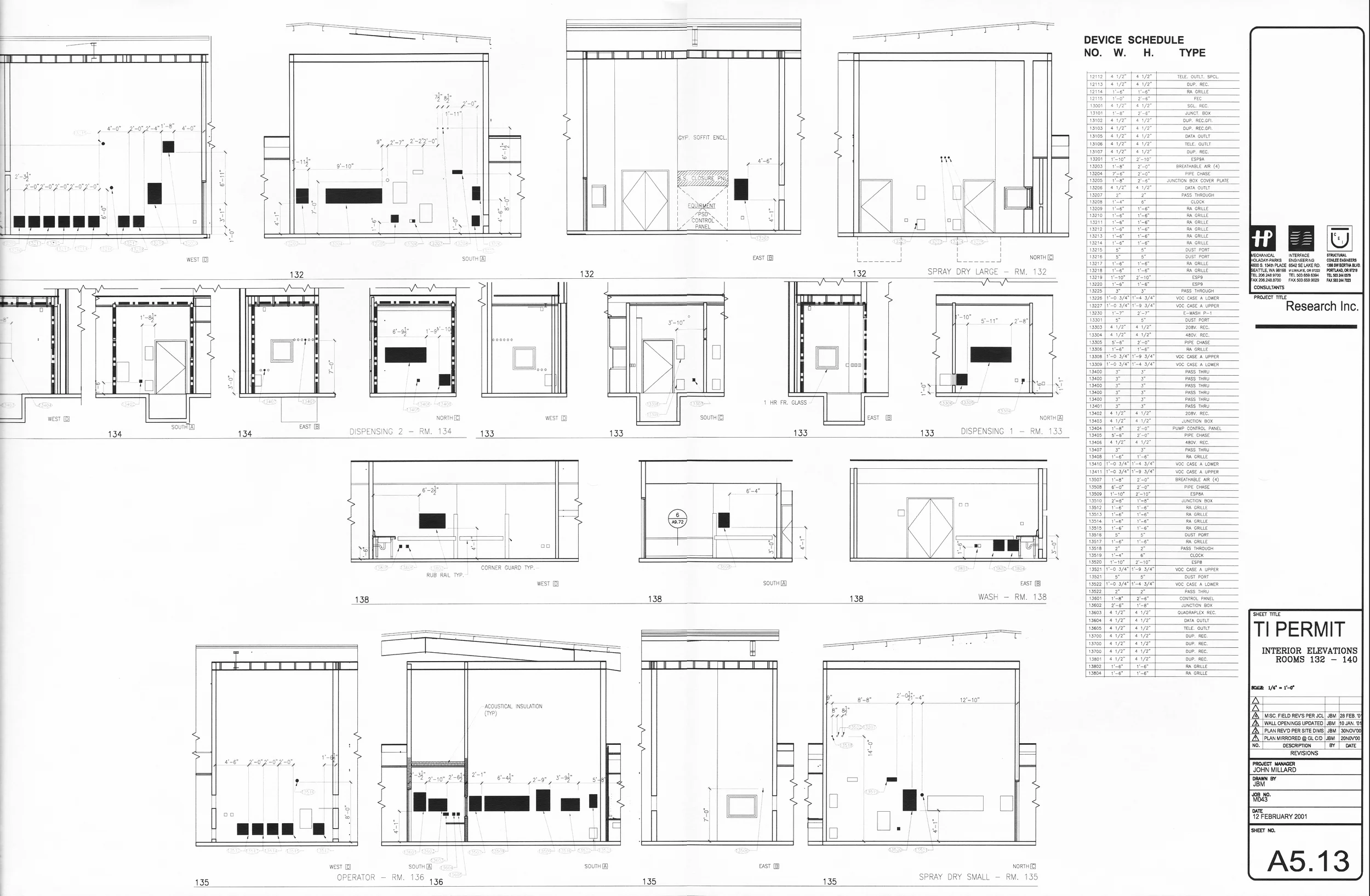
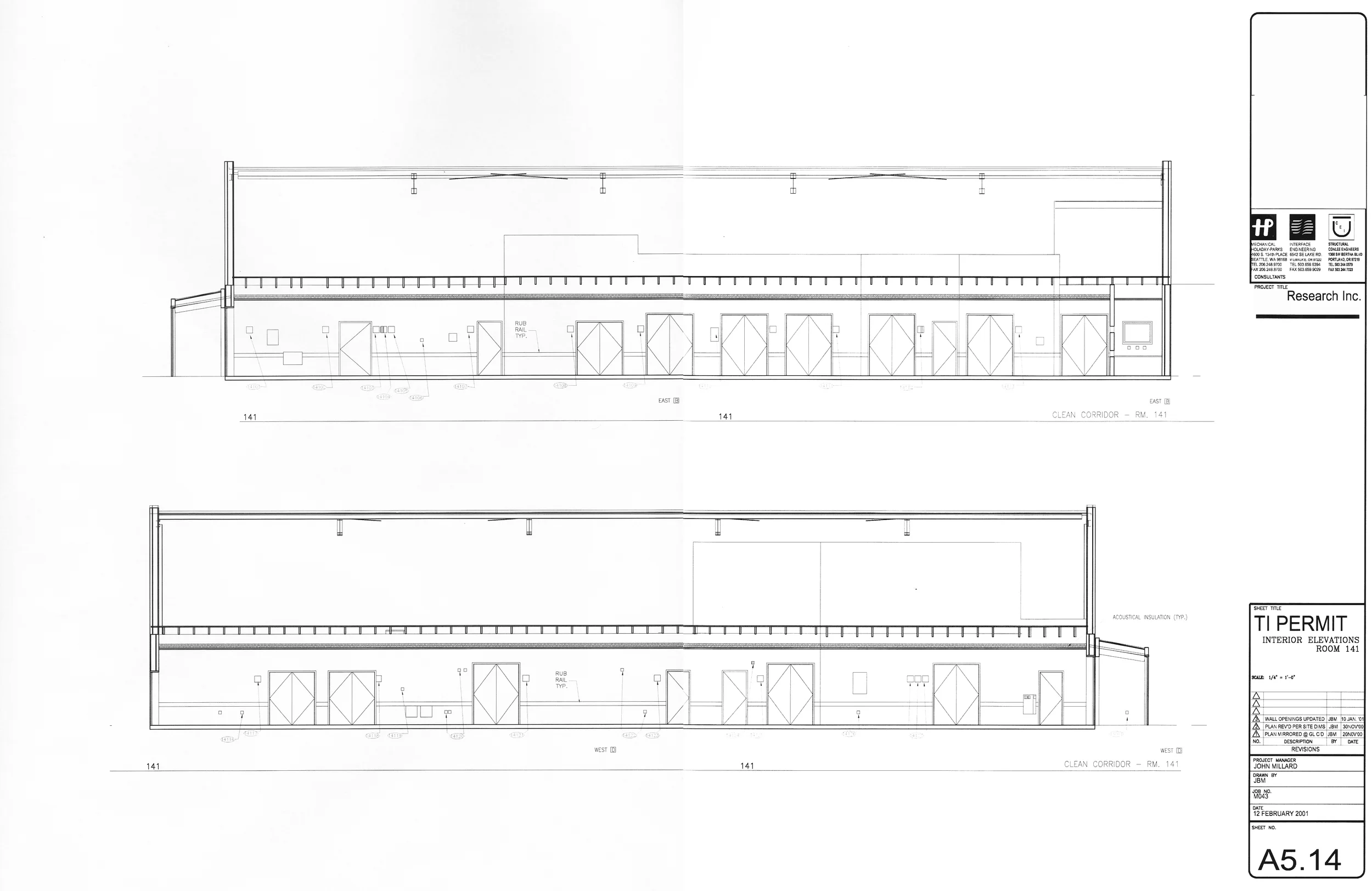
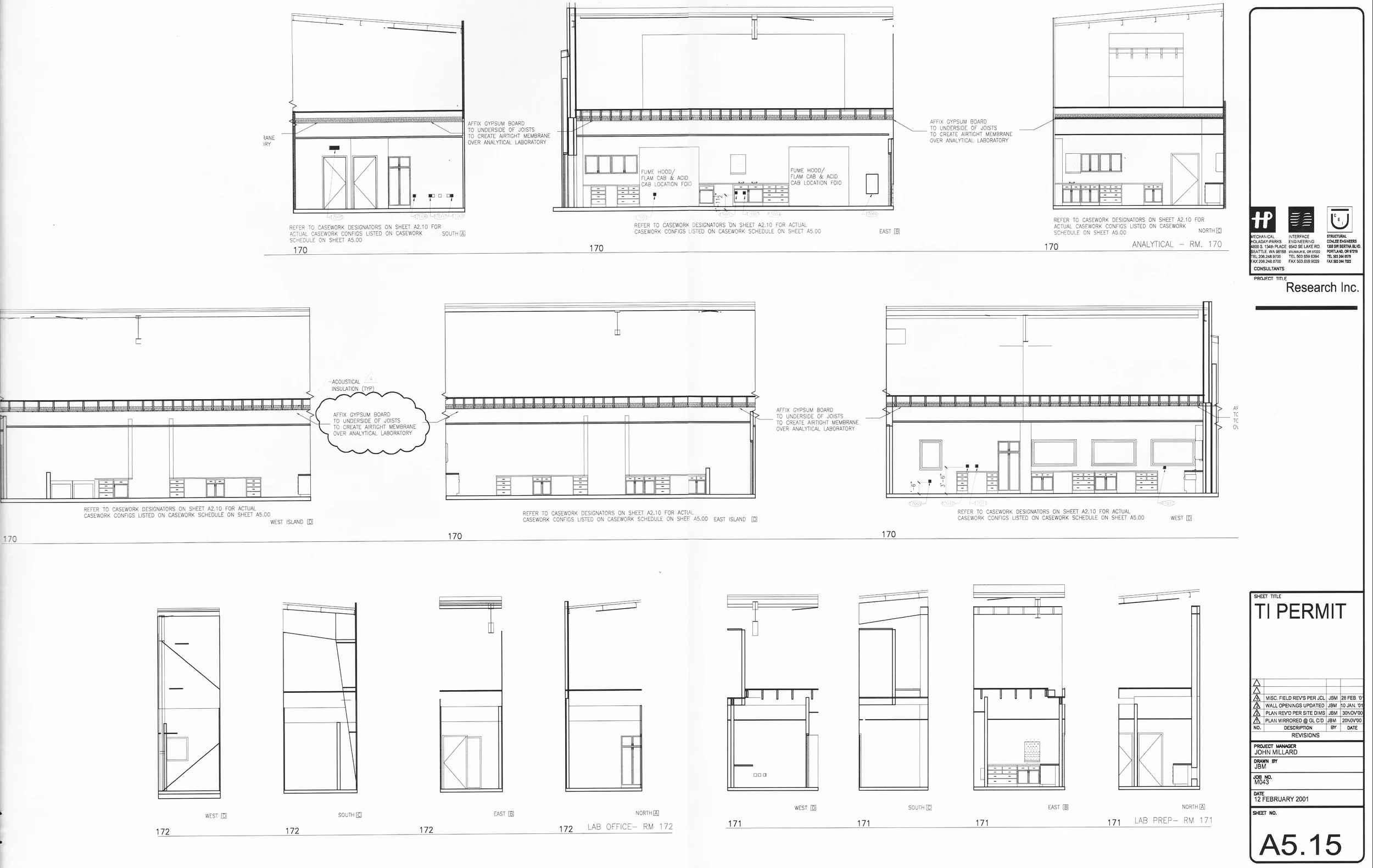
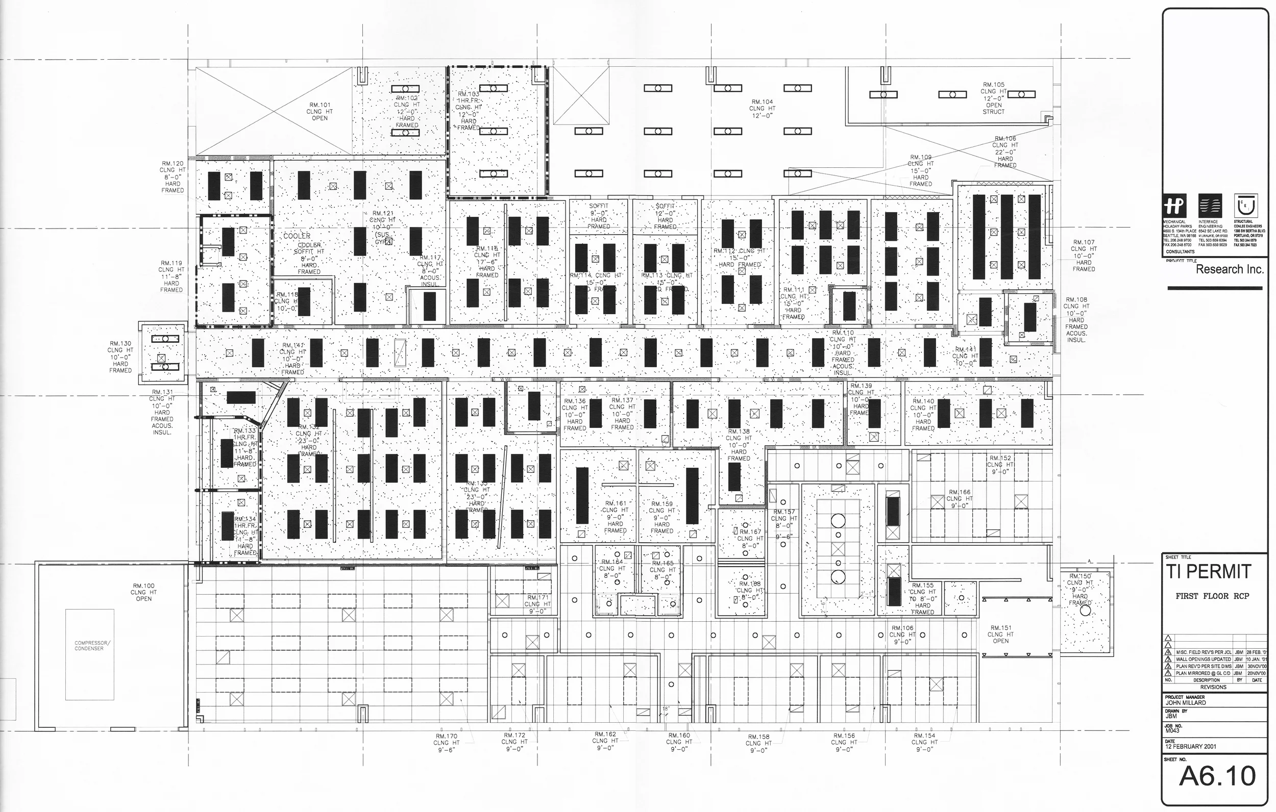
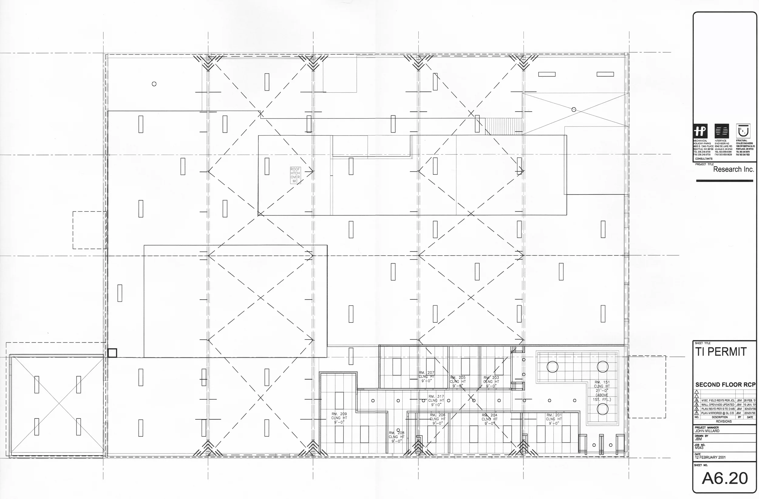
As stated above, the complex three-dimensional model that was developed in collaboration between the architect, the mechanical engineering team, the structural engineering team, and the owner was inclusive of all of the mechanical, electrical, plumbing and architectural openings in all of the walls of the proposed design. These openings and other court needed features of the design were documented in the 80% of construction drawings that have been issued prior to being notified of measuring error made by the construction management team. In order to subtract 12 inches from various locations within the proposed plan, the Spaces that would suffer from the deficit of 12 inches or some part of those 12 inches would have to be approved by the owner for reduction. It may sound like a simple exercise, shrinking the building into taxis by 12 inches–but as it happened there was no one single space across the entire width or length of the building that we could stretch this 12 inches out of. The 12 inches had to come from a complex some of dimensional decreases in the plan that would be acceptable to be owner. Consequently, the Computer aided design operations that were required in order to compensate for these dimensional changes to plan where quite time-consuming and required a great deal of court nation with components of the drawing package that we're not interactive with the three-dimensional model. At the time, Autodesk architectural desktop release three produced interior elevations and reflected ceiling plan that we're static electronic files that stood separately from the three-dimensional parametric model that defined the volume of the spaces. Therefore, when three or 4 inches was subtracted from a specific space, all of the wall openings and the reflected ceiling plan were affected. While the parametric model was extremely useful in accommodating these changes, the disconnected drawings some of which required updating and some of which did not require updating-had to be manually coordinated and corrected in a very time-consuming exercise that cost a great deal of additional money. It turned out to be an estimated 90 hour effort to subtract the 12 inches from the length and width of the building.
Fortunately for the mechanical engineering team, they had not begun the final duct design for the mechanical scheme because they suspected that additional changes may be afoot. Once the changes to the dimensions of the building were completed and all of the Wall openings were coordinated with those changes, the mechanical engineer could begin his final duct design which employed a parametric mechanical engineering modeling System called Pro Engineer. The corrected and coordinated three-dimensional model produced by John Millard was exported to the Mechanical Engineering Firm, Holiday Parks where the final duct design was incorporated and coordinated with the structure. In many cases, the lack of vertical space required by the mechanical equipment located above the functional spaces required variances in head height for maintenance and operation of the equipment. "Ducking" one's head under the steel beams that supported the roof structure became a necessary solution to lower head heights in the mechanical spaces and in some case, it was arguable if these travel routes were acceptable to the fire officer.
Early example of BIM was carried out with disparate tools by disparate disciplines. (Architectural Desktop / ProEngineer)
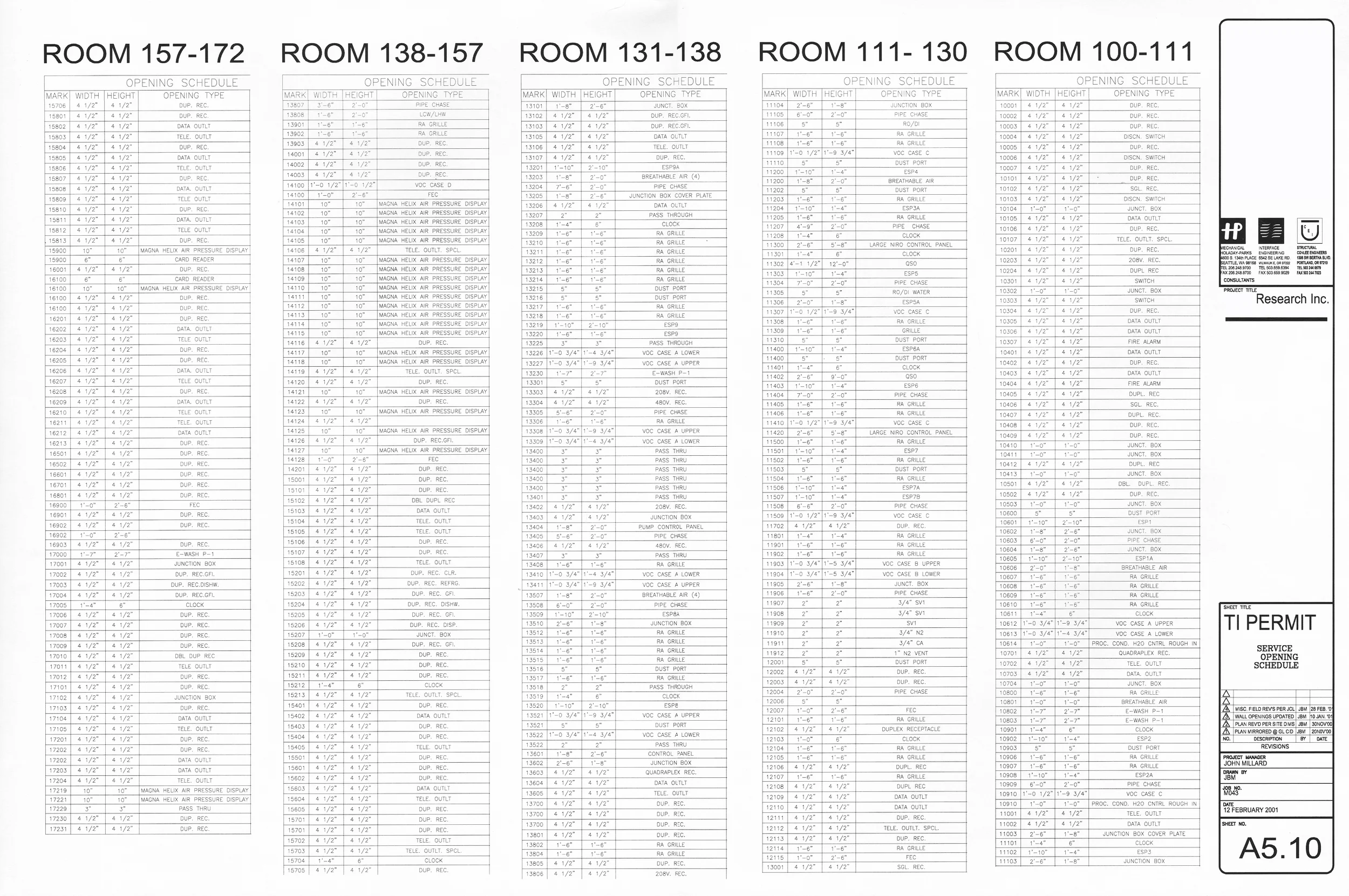
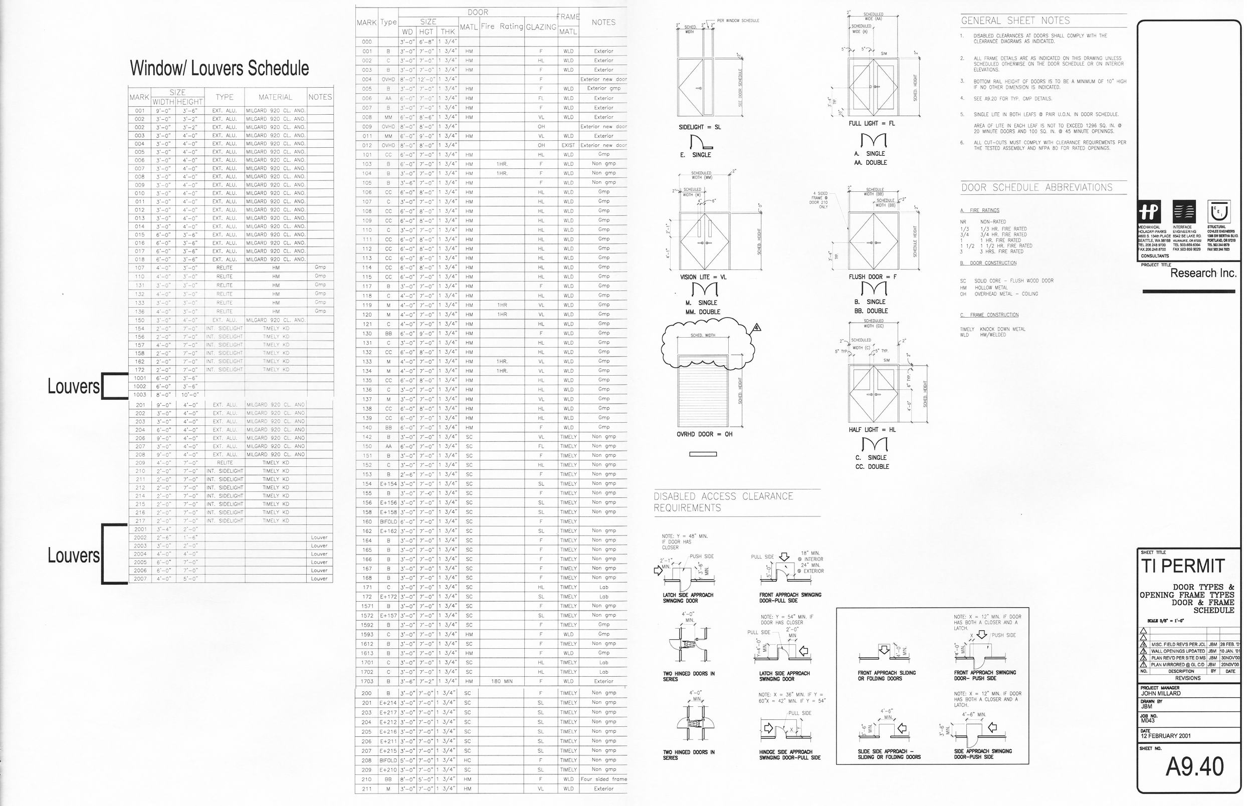
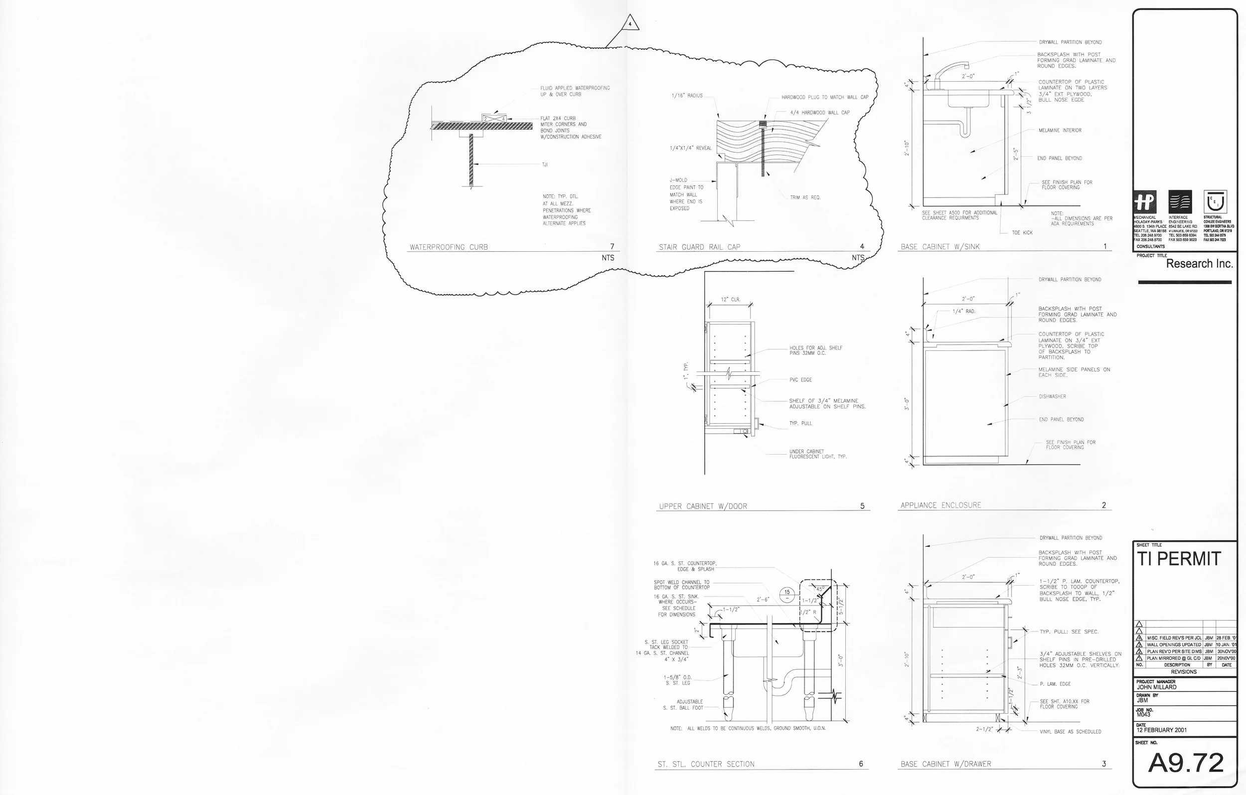
With John Millard at MBT using Auto-cad Architectural Desktop R3 and Mechanical/ Electrical Engineers at Holiday Parks using Pro-Engineer, a disconnect existed between the three dimensional models maintained by each team. Nevertheless, a high degree of transparency between the teams resulted in a close cooperation based on frequent updates of the respective models for coordination purposes. Mechanical openings in walls were the primary responsibility of the architect to closely follow the instruction of the M.E. for the location, size and specification of each opening. Export of the three dimensional model to the mechanical engineer would provide review and comment process to adjust for any revisions to openings. Likewise, the architectural model became a source of data for intelligent schedules of openings as well as windows, relites, doors and other typical architectural components such as casework, fittings and fixtures. This was made possible due to the library of intelligent objects that Autodesk and other sources (Ketiv) created for the Architectural Desktop Object Enabled Software. As the walls, doors and window openings were modeled into the architectural model, interior elevations would be created automatically using elevation tools in the software. The process of review and comment of these room by room developments of the mechanical, electrical and plumbing components were transposed initially by the hand drawn markups of the M.E. then incorporated ingot he model by the architect and checked for conflicts, accuracy and certainty in the next exchange of data by export of the three dimensional model and associated reflected ceiling plans and interior elevations.

Building Information Modelling in 2001 using ADT (Architectural Desktop) and MDT (Mechanical Desktop) Drawing: John Millard and Tim Garroute
As early as 2001, John Millard was an advocate for Building Information Modeling. The drawing above is evidence of a three dimensionally coordinated pharmaceutical powder plant governed by Good Manufacturing Practices (GMP). John Millard was the Project Manager of this project and remained in this role from inception to completion of the construction.

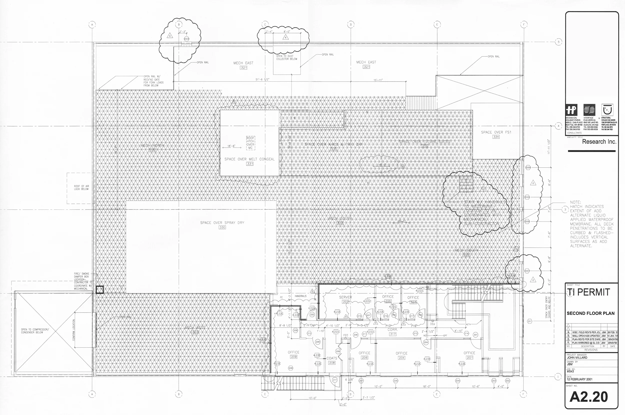
Figure 2: The plan above is coordinated with the three dimensional model above because it is the plan view of the three dimensional model in Figure 1.
This Pharmaceutical Pilot Plant was constructed in 2001. The project was led by a construction management team that required an architect to prepare design development documents for approval by the research client during a DD phase which immediately transitioned into a construction documentation phase. The Architect of Record was Peter Hockaday of MBT Architecture yet MBT, the firm that JBM was employed as Project Architect on this project was not mentioned in the title block of the drawings. This was apparently at the direction of the construction management company in order to reinforce perception that the CM was the lead discipline on the project for marketting purposes
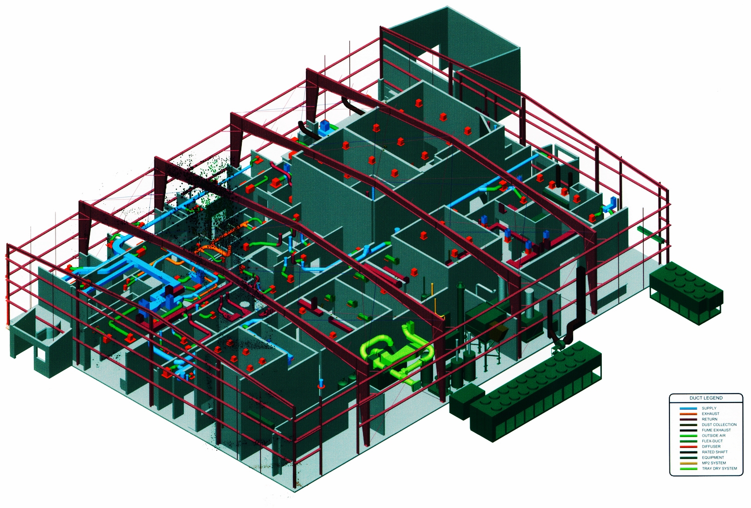
Figure 3: Lower Level Model showing structure, electrical and architectural components.
The metal framed industrial shell that became host to the pharmaceutical powder facility proved to be a close fit for each discipline to complete their respective designs. The mechanical engineering component of the overall scheme faced the greatest challenge, servicing the process equipment in each space with plumbing, heating, air conditioning and air changes that demanded only the purest air and plenty of it in order to manufacture the pharma product using GMP.
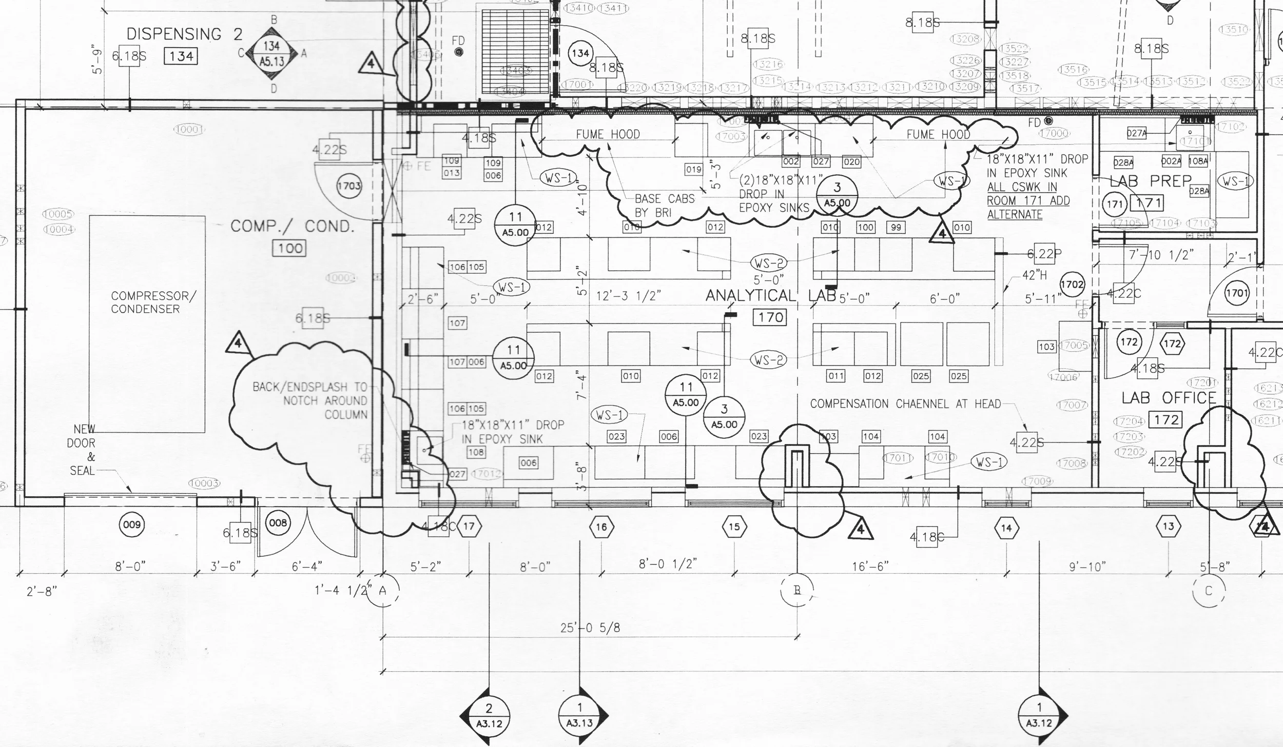
Figure 4: Plan of the Analytical Laboratory (Construction Drawing by JBM)
While most of the building was effectively a laboratory full of equipment, the analytical laboratory was equipped with fume hoods and laboratory benches, fittings and fixtures but was not a heavy research lab. The analysis of pharma product from the powder processes is the primary mission of the analytical laboratory.
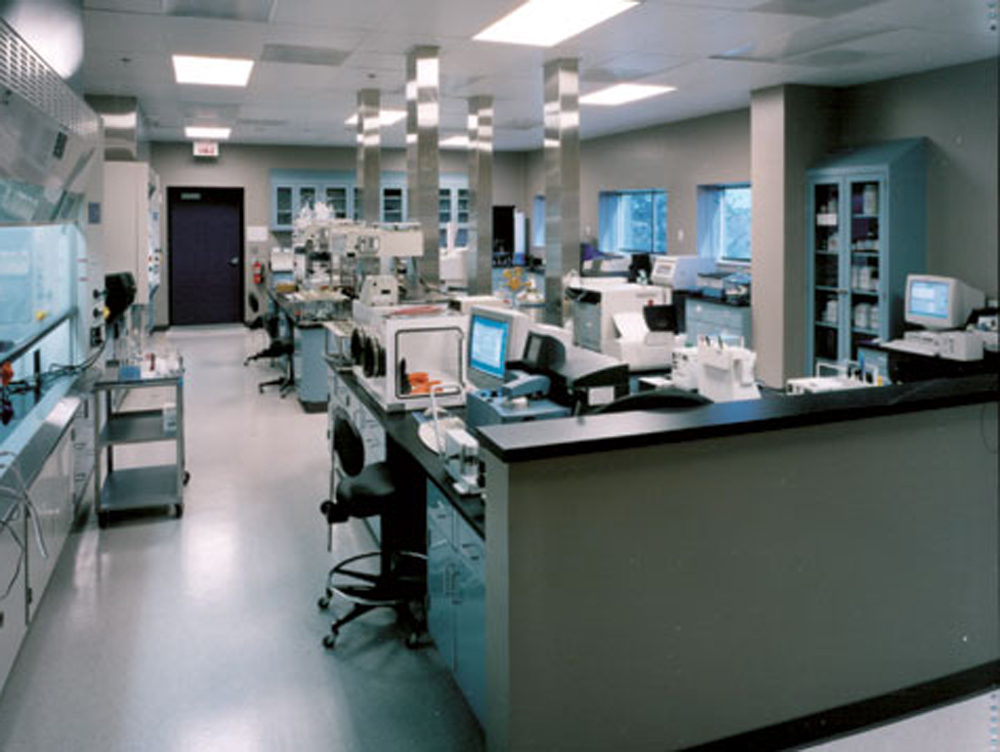
Photo 1: Analytical Laboratory Photo: Light laboratory work performed to test product quality.
As can be seen in the photo, the laboratory benches were essentially desk height worktops without shelves or upper casework and plumbing/ electrical drops to service the computers and wet applications on the central island bench. The fume hoods (to the left in the photo) adjoined the Large Spray Dry spec which had return air grilles in the wall.
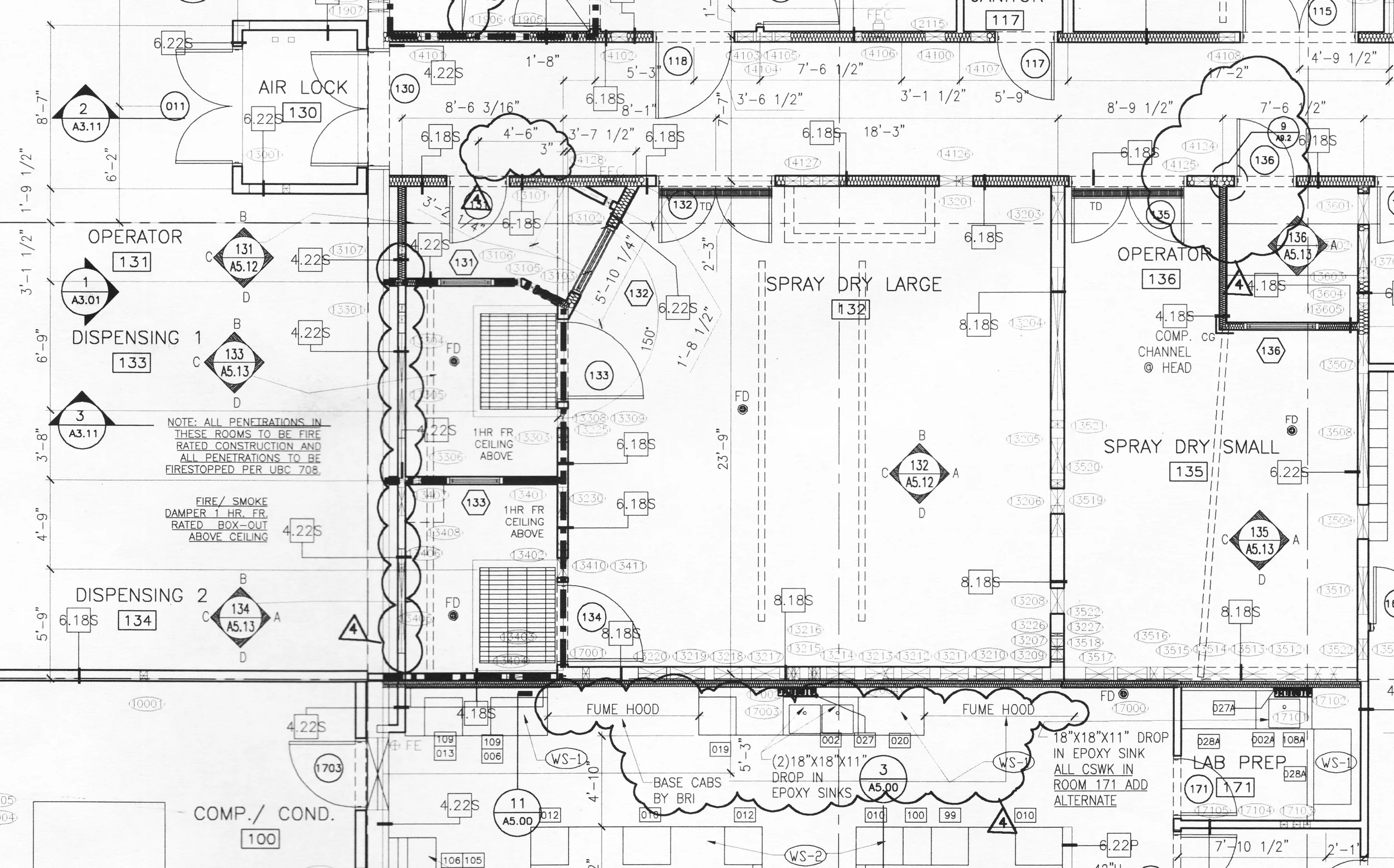
Figure 5: Large Spray Dry- One of the most heavily serviced spaces in the building.
The large spray dray equipment required a high degree of air change in order to comply not only with GMP but also with OSHA. The particulate matter that could accumulate in the air of the room requires special filters and other personal safety measures that make coordination of all electrical, mechanical and plumbing services a multiplicity of tasks.
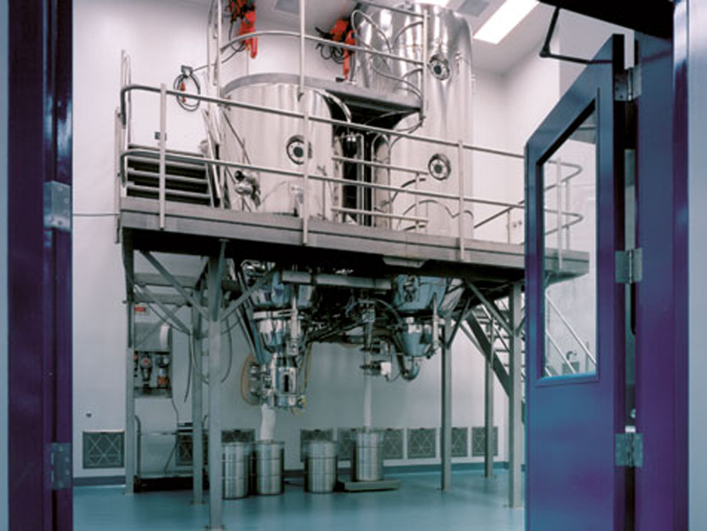
Photo 2: Large Spray Dry-
Spray drying is a method of producing a dry powder from a liquid or slurry by rapidly drying with a hot gas. This is the preferred method of drying of many thermally-sensitive materials such as foods and pharmaceuticals. A consistent particle size distribution is a reason for spray drying some industrial products such as catalysts. Air is the heated drying medium; however, if the liquid is a flammable solvent such as ethanol or the product is oxygen-sensitive thennitrogen is used.[1] (Wikipedia)

Photo 3: Large Spray Dry
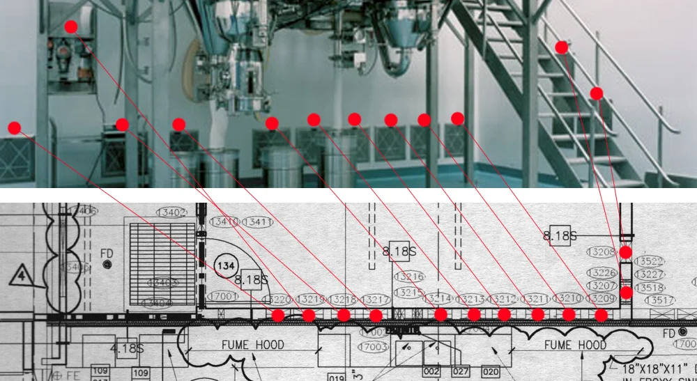
Figure 6: Sample coordination of architectural/ mechanical/ electrical design using BIM
In this example of three dimensional modeling, where the model displays as a two dimensional plan, showing typical plan features for registration by a constructor- all of the openings required by the mechanical engineer to ventilate this GMP space are shown in plan in addition to the traditional architectural openings of doors, windows and relites. Here, the openings shown in plan are reflected in an "as-built" photograph (mirrored for clarity).
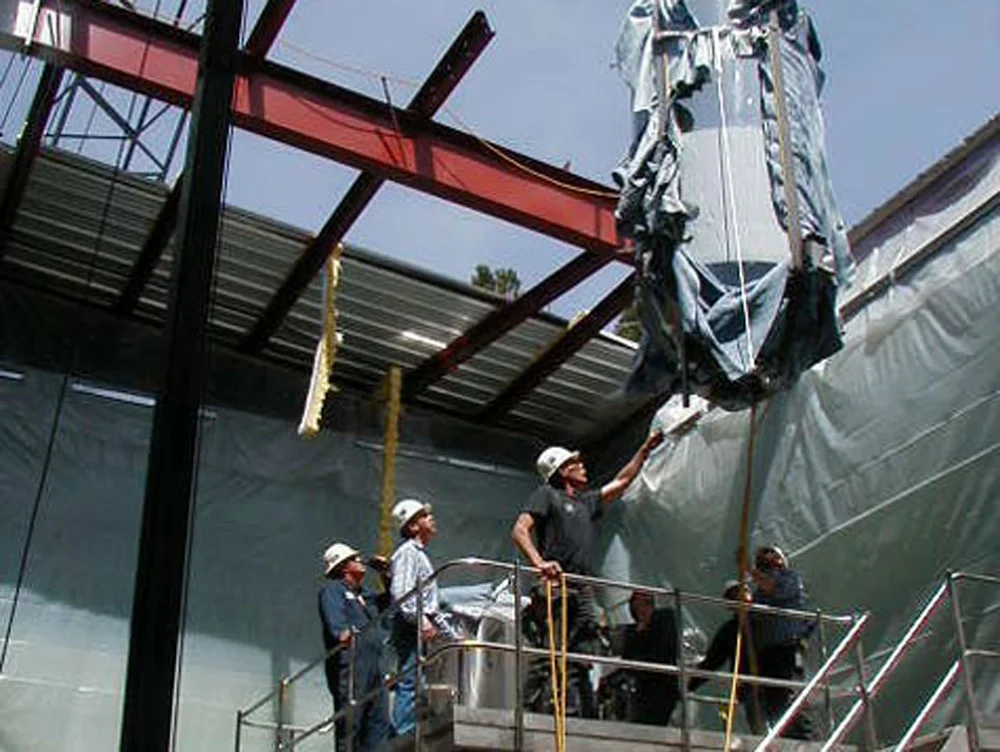
Photo 4: Construction of the Large Spray Dry Space
Construction of the Large Spray Dry Space required milestone acquisition by the construction management team, but before these milestones could be achieved, accurate and effective systems required implementation by the design team. Fundamental objectives related to the room size, finishes, lighting, access and egress for fire or other human safety purposes were defined. Then, Good Manufacturing Practices related to the code compliance that exceed normal construction codes were specified. Finally, the systems that support those standards have to be physically accommodated and coordinated within a virtual/ computer model, then clearly printed in two dimensions with traditional construction conventions.

Photo 5: Exterior View of the Pharma Plant
The metal structure that contains the GMP Facility pre-existed the design of the facility itself. This approach of dictating the volume and shape that the future facility should conform with- is not a process that served the finished design product or the construction process well. This was not caused by the these teams but by the inception and perception of the project being a "retrofit" project that would cost less if inexpensively procured by purchasing an existing structure as opposed to purchasing a new construction. It remains to be seen if this approach to the project was more or less costly.

