Multi-Custody, Large Corrections Center- Master Planned, Site Developed, Medical Center Designed
Project Summary:
Architecture Firm: NBBJ, Seattle
Date of Construction Completion: 1999
Architect Team Size: Concept Phase- 12 architects, Schematic Design- 15 architects, Design Development Phase- 18 architects, Construction Documentation Phase- 25 architects.
John Millard's Role: Concept Phase- JM authored the recommended Concept Design, Schematic Design Phase- JM role as "Site Architect" coordinated locations, functional adjacencies, topography, security and multi-disciplinary coordination of all 28 buildings with Civil, Mechanical, Electrical and Structural Engineers, Design Development Phase- JM was responsible for the design of the Medical Center, a multi custody facility with both in and out patient care for dental, trauma, psychological, and pharmaceutical services including a 12 bed infirmary with suicide watch and isolation units.
Duration of Design Effort:
Concept Design- August 1996
Schematic Design- January 1997
Design Development- May 1997
Construction Docs.- August 1997
BUILDING TOTAL AREA
200-acre site
COMPLETION DATE
Phase I—2000
TOTAL CONSTRUCTION COST
$160,000,000
OWNER
State Department of Corrections
JBM Role Synopsis:
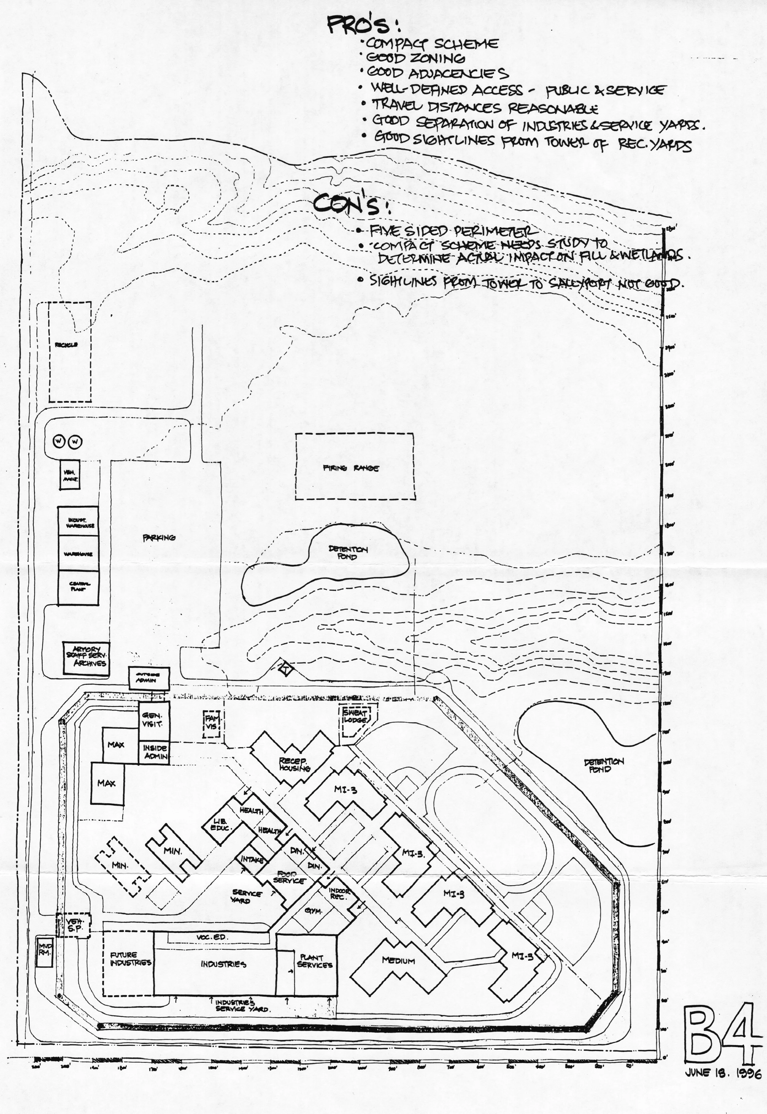
This was my first full duration project at NBBJ where I was privileged to join the project team at inception of the design. The project was a 2000 bed, multi-custody corrections center for men (location not specified here for security purposes). Previous to this role, I assisted with various medical projects, later phase efforts in the Seattle Office of NBBJ. The Medical Center inside the fence at the Corrections Center would become my personal responsibility during schematic design/ design development & construction documents but first, the team needed a concept for a compact and coherent corrections campus that met with the approval of the Department of Corrections Consortium of Security, Administrative, Industrial, Wellness, Dental, Psychological, Trauma, InPatient, Pharmaceutical, Maintenance, Food Service, Laundry and Recreation Teams the sum of whom amounted to the opinions of nearly fifty people. The Concept Phase of the Project began with information gathering, diagramming, site modeling, site visits, correctional facility tours, committee formation, charettes, break-out groups, reporting requirements, chain of communications process, design methodology and group efforts that produce a great deal of information- but after several weeks of analysis of that information it was clear that producing a design by committee was running aground. Dozens of site plans were produced through a process of team effort across three teams of four architects each. These teams grew as the effort to produce a plan that the Corrections Team all agreed was suitable became stalemated and fruitless. The larger the teams of architects grew, the more opinions mixed into the deliverables which invariable were rejected as having fatal flaws or were considered inapplicable. There was one corrections expert on the NBBJ team who had several corrections facilities in his experience and he hovered above all the architects teams, assisting with security criticism and knowledge base. Perhaps it was the process of elimination of these several dozen schemes that was necessary to arrive at the recommended scheme, but in the end- it was the corrections expert and I, locked in a room with a roll of bum wad and a clutch of sharpies that brought the 100 person process to a close by authoring what is now known as "Scheme B4". Adoption of this scheme by the Corrections Team was similar to the moment when a bride tries on the winning dress, though not every bridesmaid was "on-board" with the solution. As with many large design teams, this corrections project team were surfacing with other "individually authored" proposals after weeks of team etiquette- architects pretending that design-by-committee works despite instinctive sense of awkward drawing after awkward drawing, the products of hybridized ideas harvested in a conversation of restraint and politeness (with a lot of passive aggression and frustrations). These other "individually authored" solutions were presented one after another to the client as each individual architect became more focused and in control over his or her own pen an paper, convinced that a solution was at the fingertips. Finally, the client was presented with three solutions, an official NBBJ statement from the design team read like this:
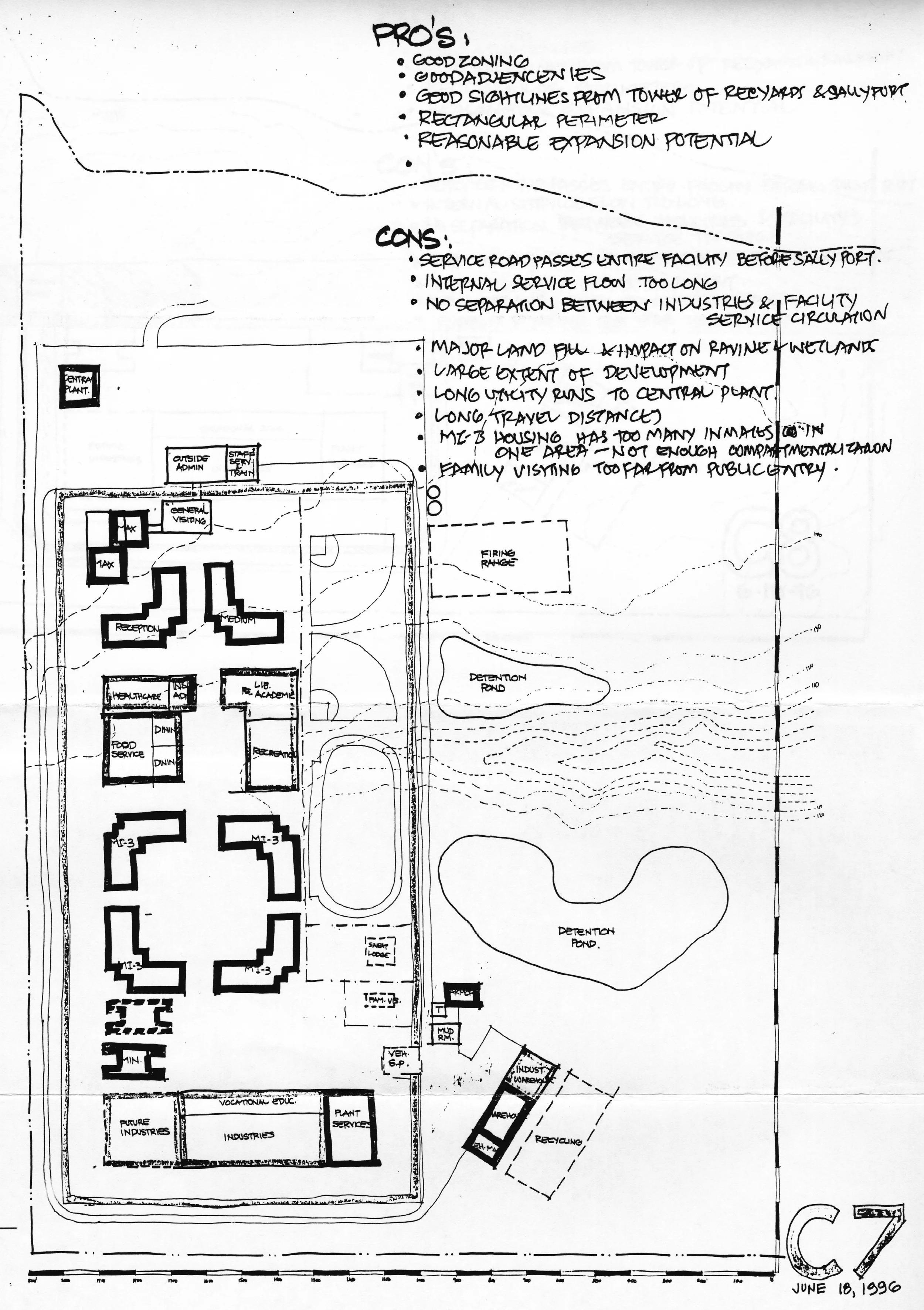
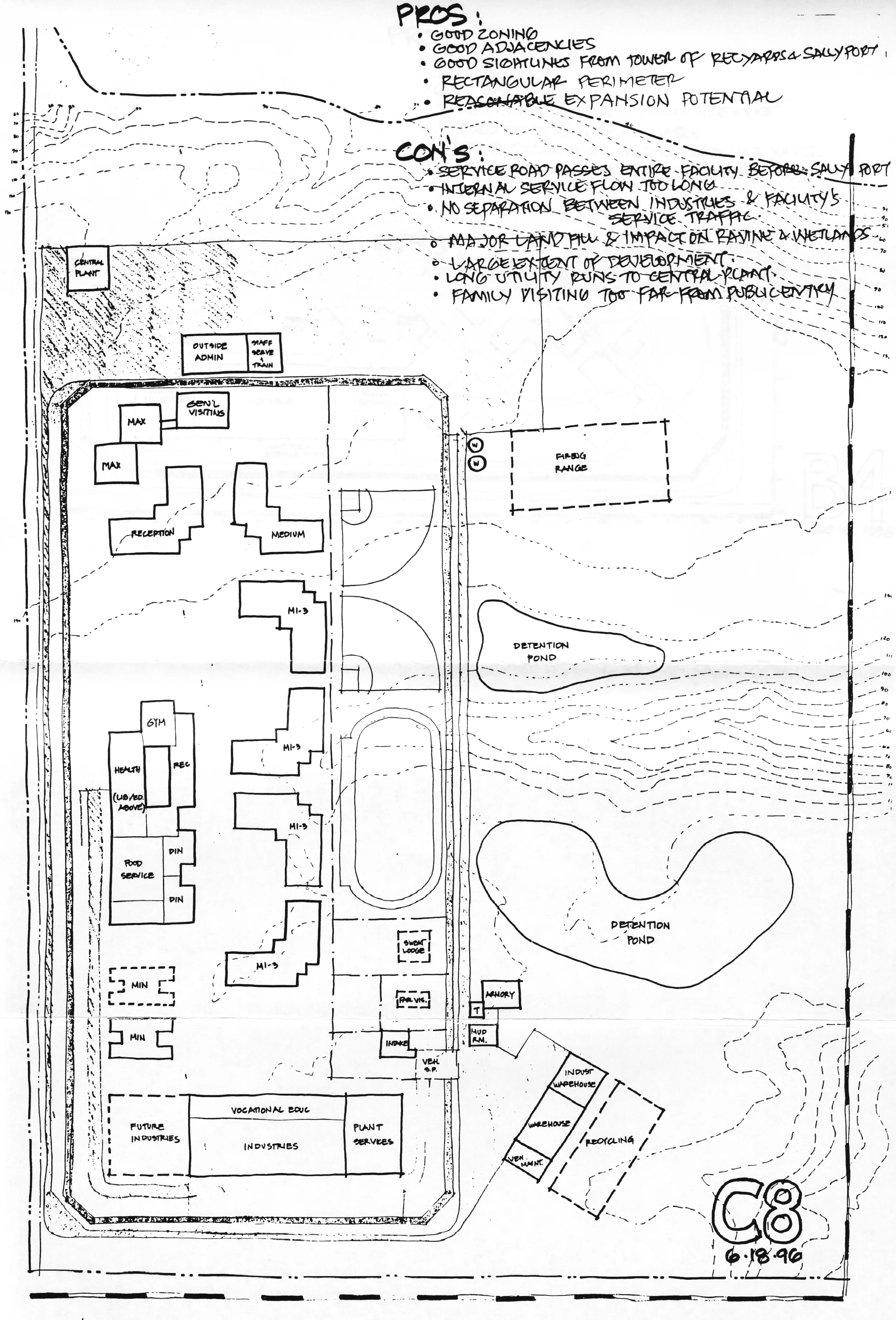
"Alternative Concept Evaluation During the planning and design process; three alternative concepts (C7, C8 and B4) emerged as candidates for further evaluation in order to proceed towards a recommended scheme. These were analyzed in a work session using a variety of criteria based on the Program Analysis and goals set collectively by DOC representatives and the Design Team. Pro's and Con's were documented and Concept B4 was selected and refined as the basis for development as the recommended option.
MASTER PLAN CONCEPT DESIGN PROCESS:
The following activities outline the process and work plan for the master plan concept development: 1. The Design Team and Department of Corrections visited the site to become familiar with site conditions. 2. A two-day kickoff charrette was held by the Design Team. Work plan tasks and approach to the development of a master plan concept were outlined: • Reviewed the work schedule. • Reviewed cost. • Deliverables were defined. • Established goals and quality expectations. • Defined consultant input and interaction. • Reviewed construction phasing. The DOC Planning Group attended the last half-day session. They reviewed the process and provided goals and objectives input. 3. The next effort was to research and setup for the concept development: • Preparation of and gathering of materials • Building a rough site model (scale coordinated with aerial photo) • Setting up a gaming approach and boards (grids applied to aerial and survey documents) • Reviewing and defining program components and relationship diagrams (Department of Corrections Policies) • Determining and setting appropriate program area building shape options • Defining infrastructure requirements, fixed conditions, code planning impacts and reading and understanding criteria (program, etc.) A work session was held with Department of Corrections to review and define program components and relationships. 4. A Design Team, multiple-option-study, kick-offmeeting was held to review research and setup material. 5. We then developed numerous multiple options. 6. DOC Executive Group met at NBBJ for an update on process and a review of work in progress. 7. After the options were completed a work session charrette was held with the Design Team and DOC, and three (3) options were selected for more detailed development. 8. The three (3) Options were developed. 9. An interim meeting with selected DOC security and operations people was held to review security and operational issues related to each scheme. 10. Another work session charrette was held with the DOC to select a recommended scheme. 11. The recommended option was adjusted and documented for Best Study. III.
SITE:
Description of Site- The Corrections Center will be located at the eastern edge of the Harbor. The site selected for the Corrections Center is atop a coastal ridgeline, and is surrounded along the western and southern edge by second growth forest and along the eastern edge by a ravine which contributes to the Existing creek drainage basin. Existing creek flows along the eastern toe of the property. The surrounding land uses include a landfill operation across the Existing creek valley, and an undeveloped ridgetop along the northern edge of the site, where the project access road will be located. The undeveloped ridgetop may be utilized for future industrial or residential development. The site is divided by a deep ravine and includes a tributary which is part of the Existing creekdrainage system. The ravine splits the ridgetop setting into two distinct buildable areas with a connecting plateau along the western side of the site. The Corrections Center location will include views across Grays Harbor and its surrounding landscape. The site has a high annual rainfall and the native vegetation is hemlock, cedar and Douglas fir forest. The northern portion of the buildable site is vegetated with a seven to eight year old growth of juvenile forest. The southern half of the site has recently been logged and only shrub cover remains. The deep ravine in the center of the site contains a series of lush native wetlands and a dense grove of large, mature alders. The ravine is of high habitat value for wildlife and provides visual interest against the dark evergreen forest.
RECOMMENDED CONCEPT:
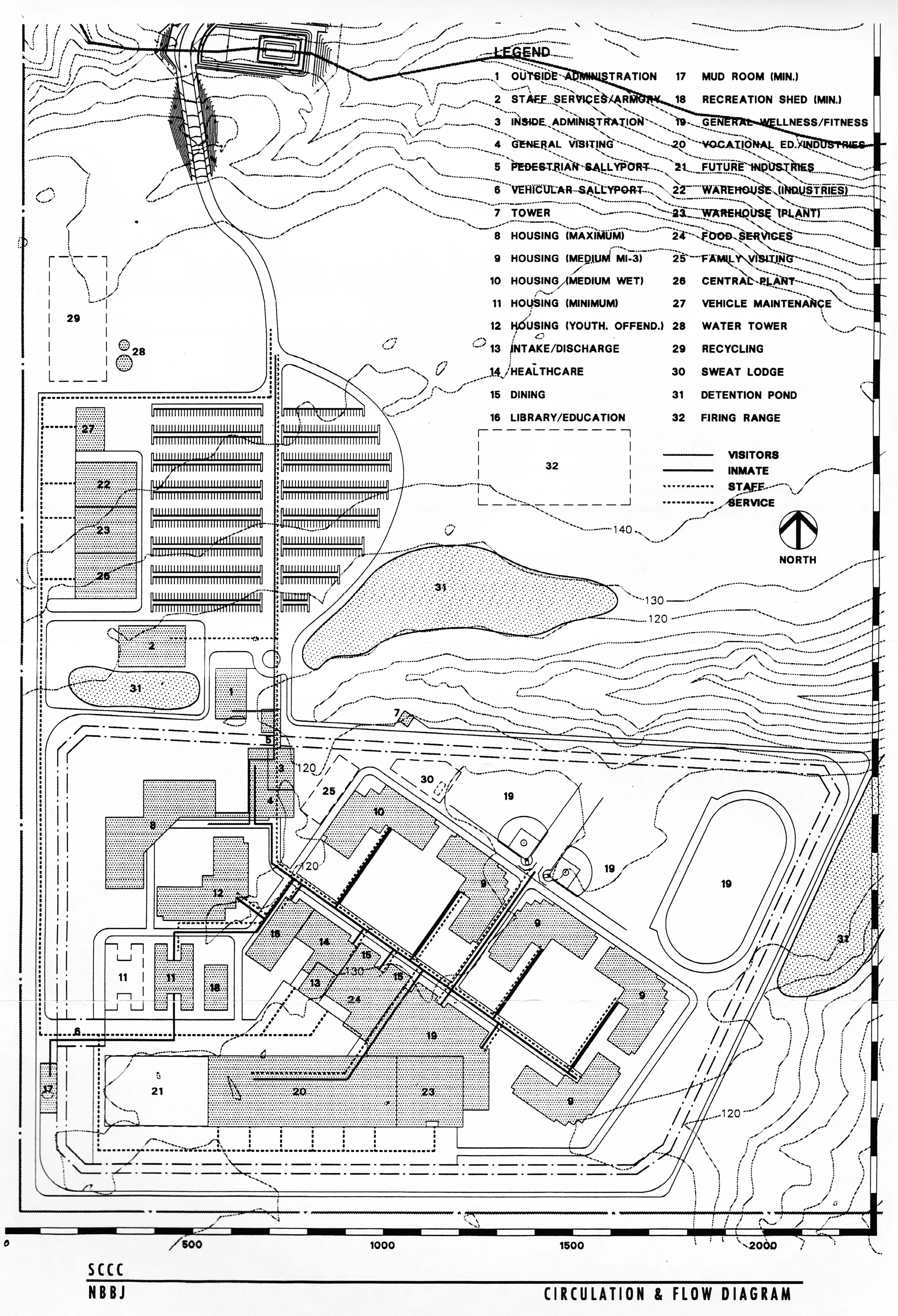
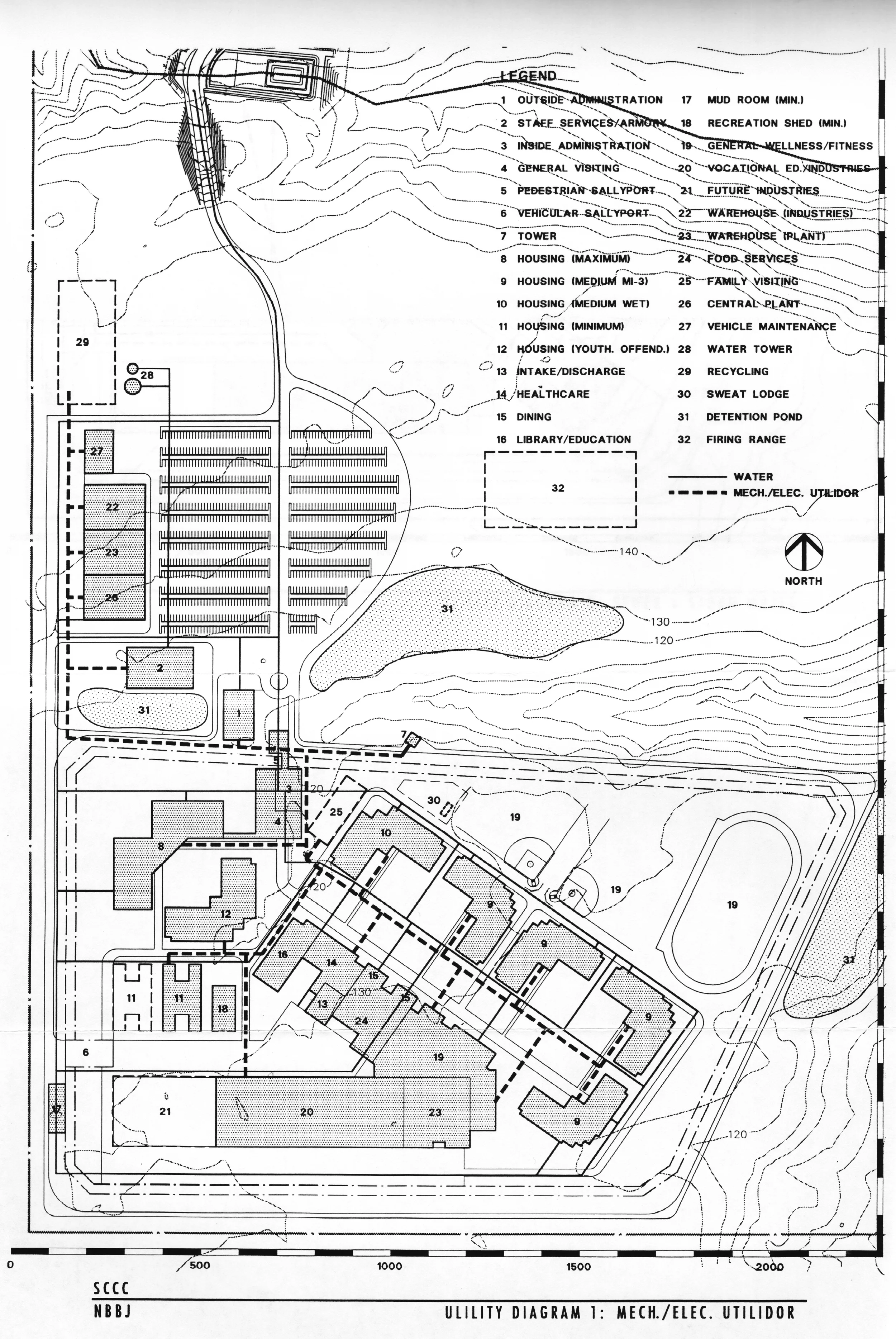
Description The concept plan for the proposed facility is based on the Correctional Center Program Analysis Update, June 28, 1996. The following excerpts from this analysis are included in Section V (Functional Area Diagrams) of this report for reference. 1. Space Summary: Correction Center 1 vs. Correction Center 2 which lists the space needs. 2. Correction Center 2 List of Building/Functional Groups corresponding to the Space Summary. The Concept Site Plan drawing that follows this narrative description illustrates the recommended concept plan. The proposed facility is located on the southern plateau of the site with its main pedestrian entrance near the northwest comer of the plateau. The main secure component of the institution is enclosed by an electronically monitored double-security fence with a patrol road around it. The overall configuration of the secure perimeter has its longer side in the east/ west direction. It accommodates all the "inside" program components within it following the adjacency/relationship diagrams developed during the planning process. The location and configuration of the Concept Plan has also been developed with the following in mind: • Conform with the required setbacks, easements and clearances. • Avoid or reduce negative impacts on the slopes and wetlands on and around the site. • Reduce extensive earthwork fills. The main approach road from the north as it enters the site will be monitored by intercom. After this check there are two clearly defined choices for access routes towards: • The main pedestrian entry and parking on the north boundary of the secure perimeter. • The "outside" service facilities on the northwest of the perimeter and the vehicular sally port on the west.
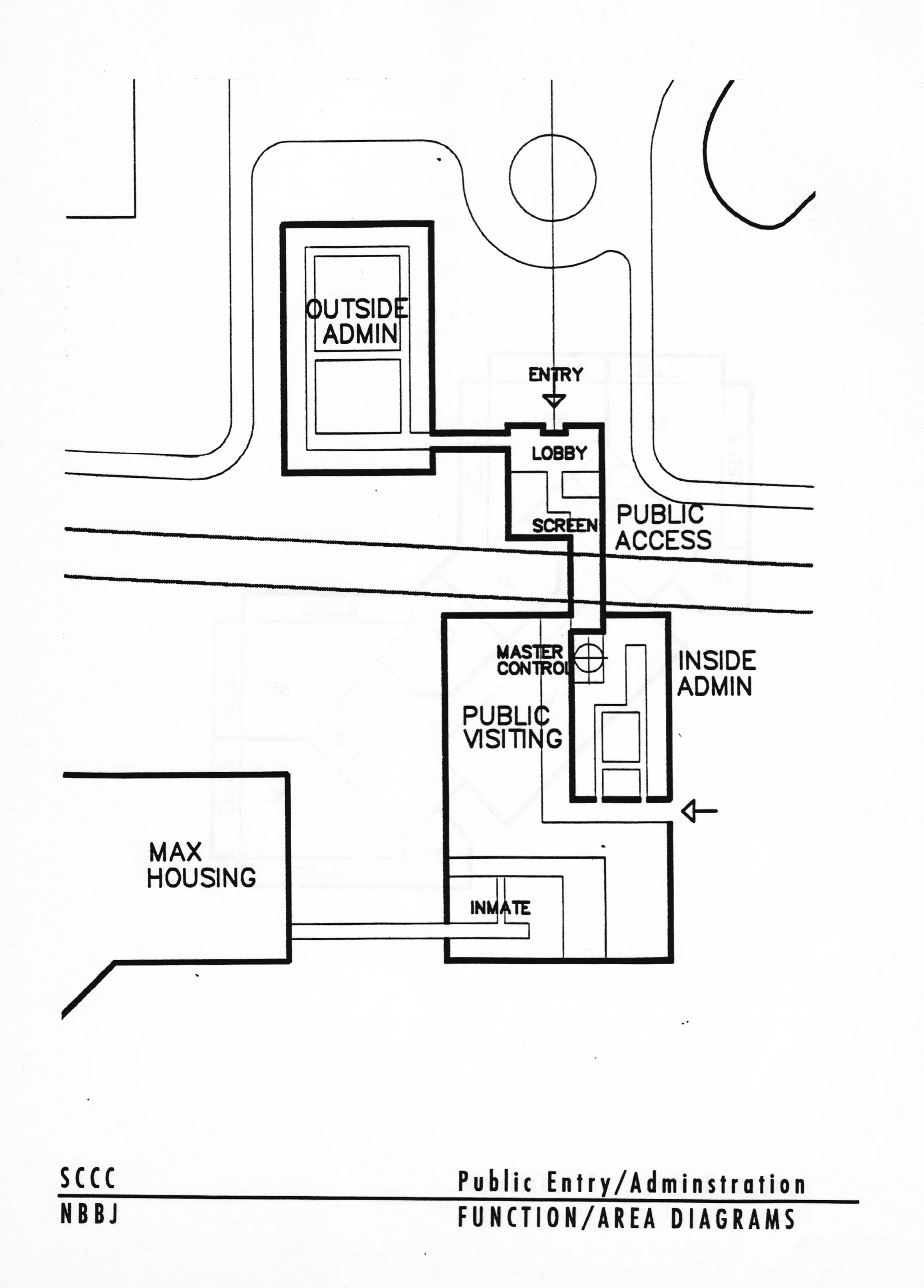
Pedestrian Entry: The main pedestrian entry is located on the north of the secure perimeter towards the west comer. All staff and visitors must enter through this entry. Entry is authorized after verification of ID and security screening as needed.
Administration: "Outside" Administration is located west of the Pedestrian Entry building to allow free access into the office areas after initial screening. The main access into the secure part of the facility is through the pedestrian sally port, which will be controlled by the Major Control room located south of this area with direct sight line observation. "Inside" Administration is on the east and south of the sally port providing direct access to the rest of the facility.
The Armory/Staff Services Training: This building is located on the west side of the "Outside" Administration building with easy access for staff.
Visiting: The General visiting area is located on the west side of the pedestrian sally port. Once visitors clear ID check and screening, they are allowed into the visiting area by major control. Inmates enter through a separate entry on the south end. ID check and screening occurs immediately after admittance before entering the visiting area. After visiting, inmates return to this area where they are checked, screened and searched to eliminate contraband before they return to housing. Attorney visiting and group meeting rooms will be located in this building with adequate separation from general visiting. Non-contact visiting booths will also be located in this area adjacent to the entry check. Inmates using these booths will be separated from the visitor area.
Vehicular Entry: Vehicles entering the facility branch to the west from the access road check point and then tum south and proceed towards the vehicular sally port, which is located on the west side of the perimeter.
The General and Industries Warehouses, Vehicle Maintenance and Central Plant buildings are located along this route on the northwest of the facility. The vehicular sally port gates are controlled by the Guard Tower with CCTV monitoring. A guard station located in the sally port screens all vehicles in and out of the facility.
Layout Inside the Perimeter: The overall organization and layout of the facility inside the perimeter is made up of several zones to facilitate clear definition of functions, flow and separation and containment of inmate groups.
General Housing: The MI-3 housing units, along with the Medium housing unit, are approximately located in the middle of the facility in a row.
The Inmate programs and services zone is located on the southwest side, and the Outdoor fitness yards are located on the northeast side in rows paralleling this housing. These yards are collectively enclosed inside a secondary fence. The housing units are paired with adequate separation (40 feet) between units. The gaps between the units also provide multiple accesses to the yards.
Inmate Services and Programs: The Inmate Programs and Services building is subdivided into zones for Education, Health Care, Intake, Food Service and Indoor Wellness Fitness areas. The Education and Health Care components will have some functions on the second floor to facilitate adequate daylight into rooms. The Indoor Wellness Fitness Program areas are located towards the southeast end of the building with a direct path to the yards. A walkway along the length of the building provides a well-defined circulation area with clearly identifiable entry points. The loading/service yard is located on the south side of this composite building with direct access to the Kitchen, Intake and Ambulance access to Health Care. View of this area is concealed from inmate areas. Industries, Vocational Education and Plant Services: The Industries, Vocational Education and Plant Services are located along the south side of the perimeter. The building will be planned as modular bays to allow multiple industries to operate independently. The Vocational education spaces will be located along the north wall of this building. Future expansion of this building will be to the west. The loading/service area for this building stretches along the south face of the building to serve multiple industries independently. This also provides a clear separation of the industries and facility-related service areas. The Plant Services component is located adjacent to the Industries building on the east end. A single point inmate entry is provided from the north side of the building to facilitate screening and flow of inmates.
Minimum Security Housing: The Minimum Security housing unit is located on the western portion of the facility in close proximity to the vehicular sally port to facilitate convenient movement of these inmates to work detail outside the perimeter. The Mud room for check, search and clothing change is located outside the perimeter close to the vehicular sally port. The Minimum housing area can be separated from the rest of the facility with a secondary fence. Inmates from this zone will mix with the general population and go to the services and program spaces on a prescribed schedule.
Higher Security Housing: The Youthful Offender housing and the Maximum/Segregation housing are located in the northwest comer of the facility in a separate zone. The Max/Seg units are located on the northwest comer of this zone with cells facing away from the rest of the facility. The location is close to the visiting area building with a secure connection to facilitate controlled visitor access to the Max/Seg unit. The Youthful Offender housing is located south of the Max/Seg housing building in close proximity to the Intake area in the Inmate Services building.
Other "Outside" Buildings: Buildings other than the Pedestrian Entry and "Outside" Administration that are located outside the perimeter fence include Industries and General Warehouses, Central Plant, Vehicle Maintenance buildings and the Water reservoirs which are located in a row parallel to the west edge of the upper plateau of the site. The north/south run of the vehicular access road runs along this row of buildings to provide easy access to the vehicular sally port, which is to the south or towards the approach road of the highway (north). Areas are also earmarked for miscellaneous buildings such as Recycling (north of this area) and a Firing Range on the east side of the north plateau. Guard Tower: This facility is based on the concept of a single guard tower. The prescribed highest priority for the location of the guard tower is to be able to visually supervise the fitness yards, the family visiting area and the sweat lodge. The secondary priority is to be able to supervise the vehicular sally port and the service yards. Additionally, the tower should be able to observe incoming traffic from the approach road onto the site. With these criteria in mind, the guard tower has been located on the north side of the perimeter fence west of the Main Public entry.
Site Work and Utilities: Summary descriptions on Site Development, Civil, Structural, Mechanical and Electrical are included here along with Conceptual diagrams of the Utilities.
SITE DEVELOPMENT:
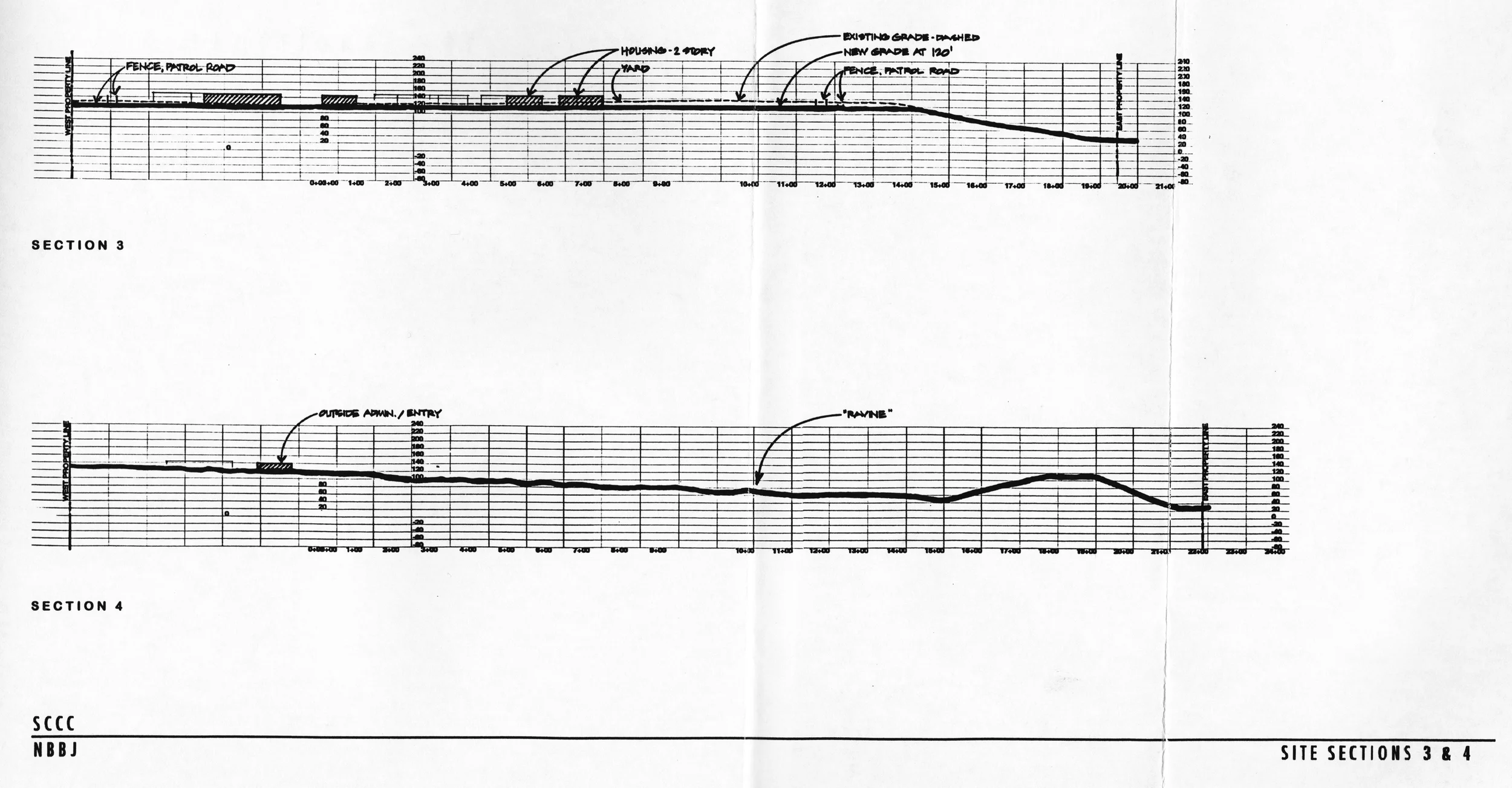
The concept locates the primary facilities within the southern half of the site. This location will minimize the visual impact of the facility from off-site vantage points. The proposed layout will minimize the amount of cut and fill necessary within the ravine. The diagonal site layout will provide the opportunity for landscape terracing within the facility. This will minimize earthwork and create distinct use areas within the Corrections Center. Scheme can incorporate storm water detention facilities within the eastern end of the southern plateau, and a separate detention pond for the parking area within the northern plateau. The microclimate created within the layout will provide southwestern exposure to the central walkways, which will maximize sun exposure and drying of walkway areas. The layout will also orient the entrances to the living units in the direction of the prevailing winter winds and create a windy, rain-driven entrance. The design of buildings will need to consider this factor. The plan provides a good solar orientation for the recreation fields. The location of the facility within the southern plateau takes advantage of the recent forest clearing within this area. The majority of the juvenile forest along the northern plateau will be preserved under this development plan. This will retain both additional wildlife habitat and vegetative buffer for the sensitive ravine environments. Vehicular access to the site will be functional and the division of traffic between the parking area and the service entrance will take advantage of topographic site opportunities. Pedestrian circulation within the site will be channeled along a central corridor and travel distances will be minimized between living units and service areas. The location of the facility along the southern plateau will minimize the impact of security lighting on the surrounding vicinity; however, glare from the lights will be visible from the surrounding ridgelines. The Scheme will have an excellent visual sense of entry to the Corrections Center. The location of the entrance road in relationship to the administration building, combined with accent landscaping, will create the opportunity for developing a positive institutional image. The location of the outside industries and warehouses along the western edge will create a buffer between any future land use of the adjoining western parcel and the Corrections Center.
WATER UTILITY:
The water supply will be furnished by the City of Aberdeen. Water will be supplied to 2 - 150 foot tall standpipes located on high ground on the west side of the north plateau. One standpipe will be for domestic supply, the other for fire protection. Domestic demand on the peak day is estimated at 1100 g.p.m. Fire demand is 3250 g.p.m. for 4 hours or 800,000 gallons, with a minimum 20 psi residual pressure. All buildings will be sprinklered and exterior hydrant spacing will be on the order of 300 feet. Distribution piping will be mostly 12 inch diameter ductile iron pipe. Water demand for irrigation is included in the above figures.
SANITARY SEWAGE UTILITY
Sewage waste will be delivered to a City of Aberdeen facility adjacent to SR1 05 and then pumped back to Aberdeen for treatment. The on-site collection system consists of 8 to 12 inch gravity sewers. Schemes, which occupy the south plateau, require a pump station and force main to lift waste to the north plateau. Collected waste on the north plateau will flow by gravity to a second lift station near the top end of the new access road. It is then discharged to the Aberdeen facility at SR1 05. STORM DRAINAGE UTILITY Storm runoff in the area is extensive, averaging 86 inches of rainfall per year and 4 to 5 inches in 24 hours. On-site storm collection will be carried in closed pipe ranging in size from 12 to 24 inch diameter. Storm water will be diverted to detention ponds and possibly bio-filtration swales prior to discharge into existing creek and its unnamed tributaries. Pre-treatment of runoff from parking lots and vehicle wash facilities may be required.
EARTHWORK On-site soils are not good with regard to use as a base for structures. The soil has a high fines content and is not capable of the required compaction for use under structures because of the high moisture content. Soil classified as cut will be classified as unsuitable. This includes the top 12 to 18 inches, which is high in organic material. The requirement for imported fill material will be high, driven primarily by the need to level the site for security reasons. The footprint of some schemes intrudes on the ravine that divides the overall site into two plateaus. The ravine is a designated wetland and the filling of it and other wetlands require a permit from the Corps of Engineers. The primary intent of the final grading plan for the selected site will be to reduce the amount of imported fill to the minimum possible.
Foundations • It is anticipated that all of the buildings will be located on structural fill as determined by the geotechnical engineer. • Some initial settlement could occur and will have to be considered in the structural design. • Some heavily-loaded or settlement-sensitive structures may have to be supported on high capacity foundations such as auger cast piles. These may include water and fuel storage tanks, lighting towers, and the guard tower. • It is recommended that additional geotechnical information be obtained when the final site layout has been selected. This information should include the soil bearing capacity, lateral soil pressures, and soil friction factors. Borings up to 30 to 40 feet deep, and one boring up to 60 to 70 feet deep may be required. Buildin~s Possible types of construction that are to be considered include: • Tilt-up concrete. • Pre-cast concrete. • Cast-in-place concrete. • CMU with special reinforcement and grout-filled cells. • Structural steel. • Possibility of wood construction for buildings where security is, not a strong consideration. Other considerations relating to the design of the buildings include: • Establishment of efficient modules that will allow duplication within the various structures. • Special security requirements for exterior and interior walls may control the design. • Special consideration must be taken for crack control due to settlement of foundations. • Other special requirements that may effect the design. May include hoists, cranes, or other heavy equipment, or long-span requirements.
Site / Utilities • Water or fuel storage tanks could be cast-in-place concrete, pre-cast concrete, or steel construction. • Utilidors could be cast-in-place or pre-cast concrete construction. Water protection will be required. • Oil/water separators could be obtained and installed as complete units, or they could be designed to be built on site. Other site / utility structures to be considered include: • Pump stations. • Site lighting towers. • Guard tower. • Retaining walls. • Emergency generators' installations. • Stack at power plant.
Mechanical System: The main utilities serving the Site have a direct path to the Power Plant and do not impact the construction of Buildings within the Security Fence. Adequate access is provided for vehicles to service the mechanical equipment located within the Power Plant. The site plan allows for a direct path for the installation of utilidor containing heating piping, domestic cold water piping and electrical conduit. The Power Plant is located to provide future expansion to the North Plateau.
Electrical Power and Communications Service: Electrical and communications services will be coming to the site along the entry road, which enters the plateau at the northwest corner. It is therefore advantageous from an electrical service standpoint to locate the power plant and associated electrical service nearer to the northwest corner. Site Distribution: The compactness of the site should result in minimized cost for power and communications distribution. The power and communications distribution may be located in the utilidor or run separately in ducts and manholes. An analysis of these two options should be performed at the Schematic Design Phase.
Power Distribution System: The power will be distributed throughout the site at 12.47 or 13.8 kV and stepped down to 277/480 or 208/120 volts via pad-mounted transformers. The system will be designed to maximize flexibility and reliability. Due to the compactness of the site, locating pad mounted transformers will require careful consideration. Emergency Power: Central emergency power will be provided to maintain the facility in operation during an extended power outage. It is assumed that the generators will be located in or near the power plant. The generators will be diesel powered, designed to start automatically upon loss of utility power. It is anticipated that three generators will be provided, sized to allow one generator to be de-activated at any time for maintenance or repairs. Site Lighting: Lighting poles will be situated throughout the facility to provide the desired level of general illumination for security and scheduled activities during darkness. Light fixtures will be cutoff type to minimize "light pollution" to surrounding areas. Perimeter fence lighting will be provided for security.
BUILDING SYSTEMS ASSUMPTIONS
FOUNDATIONS:
STANDARD SPREAD FOOTINGS
ASSUMES GOOD BEARING SOILS - NO DRILLED PIERS
SUBSTRUCTURE:
SLAB ON GRADE - ASSUMES NO BASEMENT
SUPERSTRUCTURE:
CONCRETE DECK UPPER FLOORS ON CMU & CONCRETE BEARING WALLS
CONCRETE DECK ROOF ON STEEL FRAME STRUCTURE
EXTERIOR CLOSURE:
CMU BEARING WALLS WITH INSULATION AND CMU VENEER FACE BLOCK
POLYCARBONATE GLAZING AT SECURE AREA WINDOWS
ROOFING:
BUILT-UP ROOFING AT LOW-SLOPE ROOFS
STANDING SEAM METAL ROOFING AT GABLED ROOFS
INTERIOR CONSTRUCTION:
PAINTED EXPOSED CONCRETE AND CMU WALLS
PAINTED GYPSUM WALLBOARD AT SELECTED DRYWALL CONSTRUCTION
EXPOSED CONCRETE FLOORS WITH RESILIENT FLOORING IN SELECTED AREAS
EXPOSED CONCRETE CEILINGS WITH ACOUSTIC TILE IN SELECTED AREAS
CONVEYING SYSTEMS:
MINIMUM REQUIREMENT HYDRAULIC ELEVATOR ACCESS IN MULTI-STORY INFIRMARY
MECHANICAL:
HEATING AND COOLING FROM ROOFTOP UNITS
FIRE PROTECTION SPRINKLER SYSTEMS THROUGHOUT
ELECTRICAL:
ALL LIGHTING AND POWER ON EMERGENCY POWER
TAMPERPROOF FLUORESCENT LIGHTING"
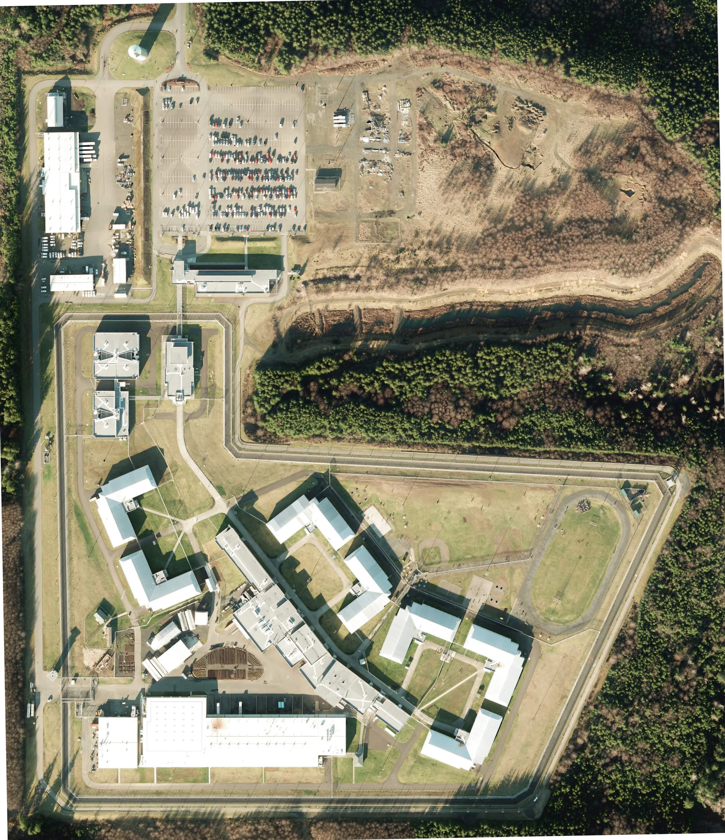
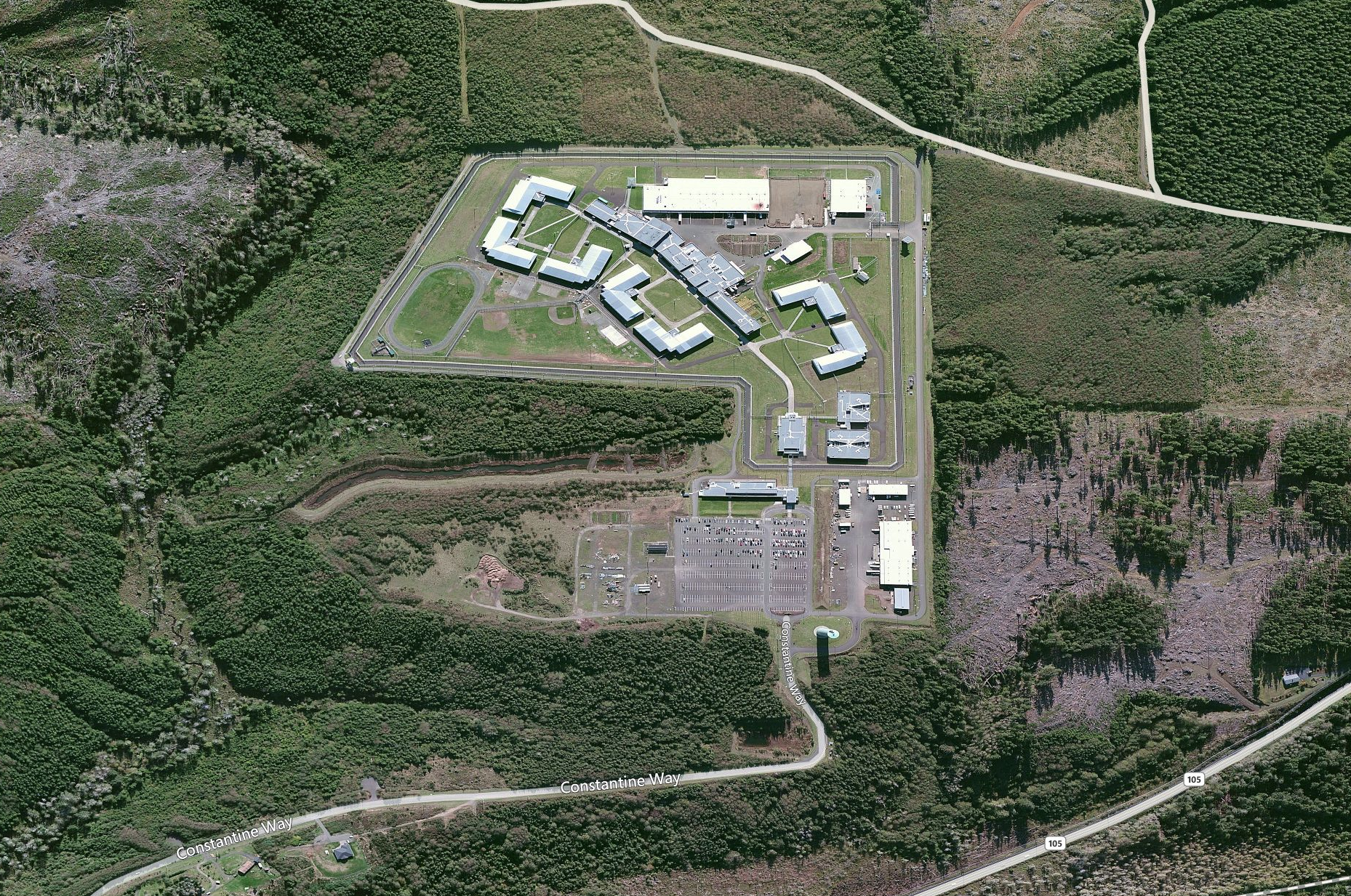
Figure 1: Satelite photo showing the corrections facility as constructed.
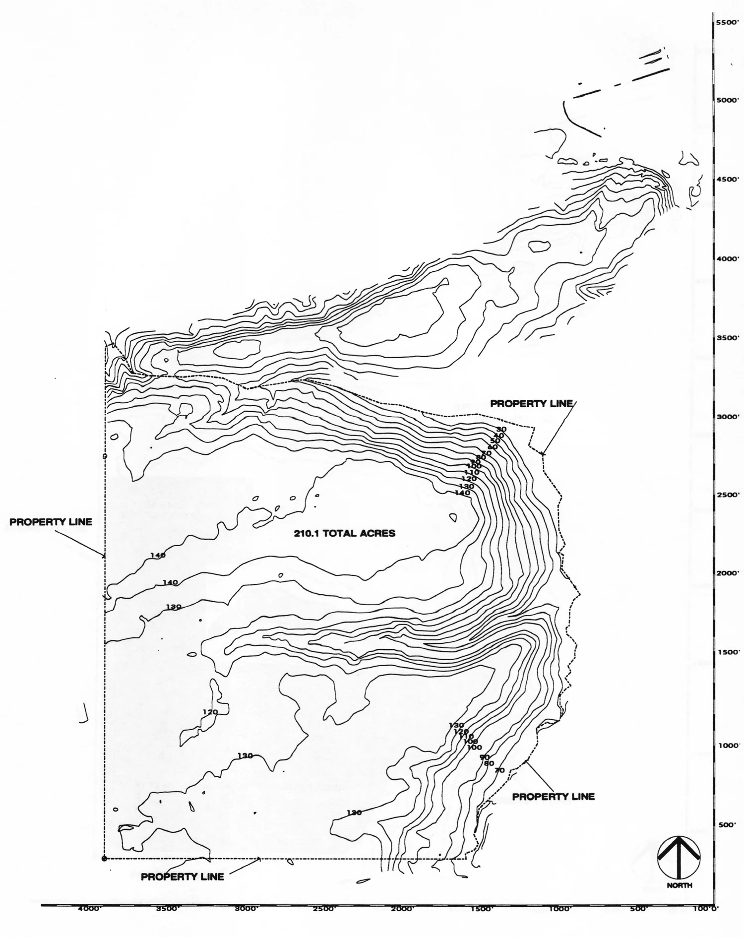
Figure 2: Existing Site Plan

Figure 3: Aerial Photo showing the project from the North
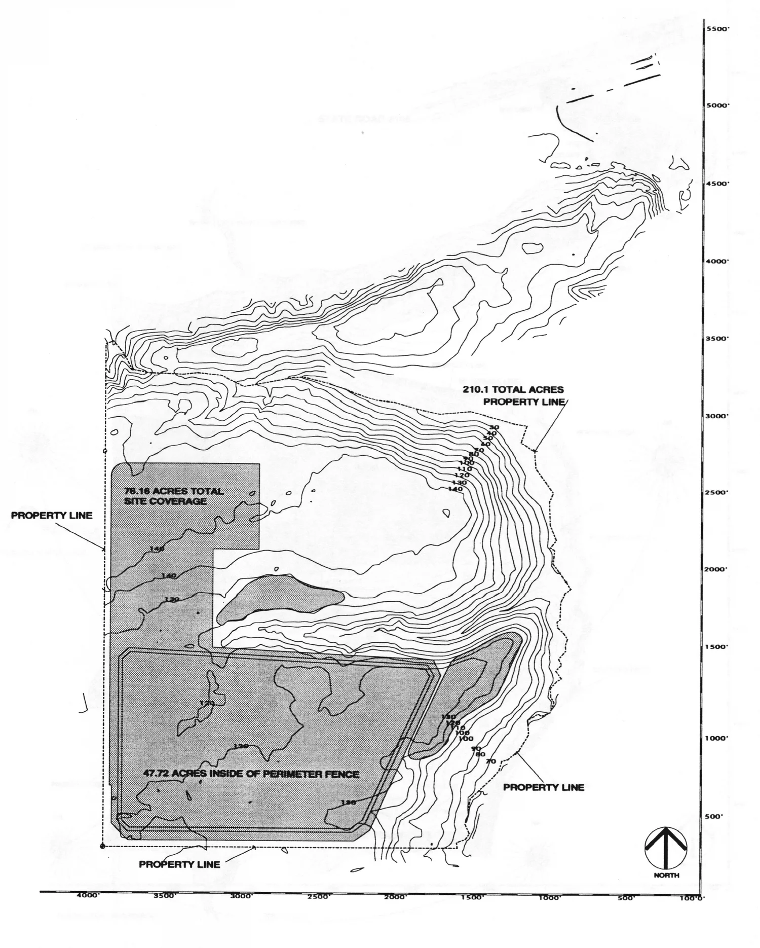
Figure 4: Land Parcel Plan
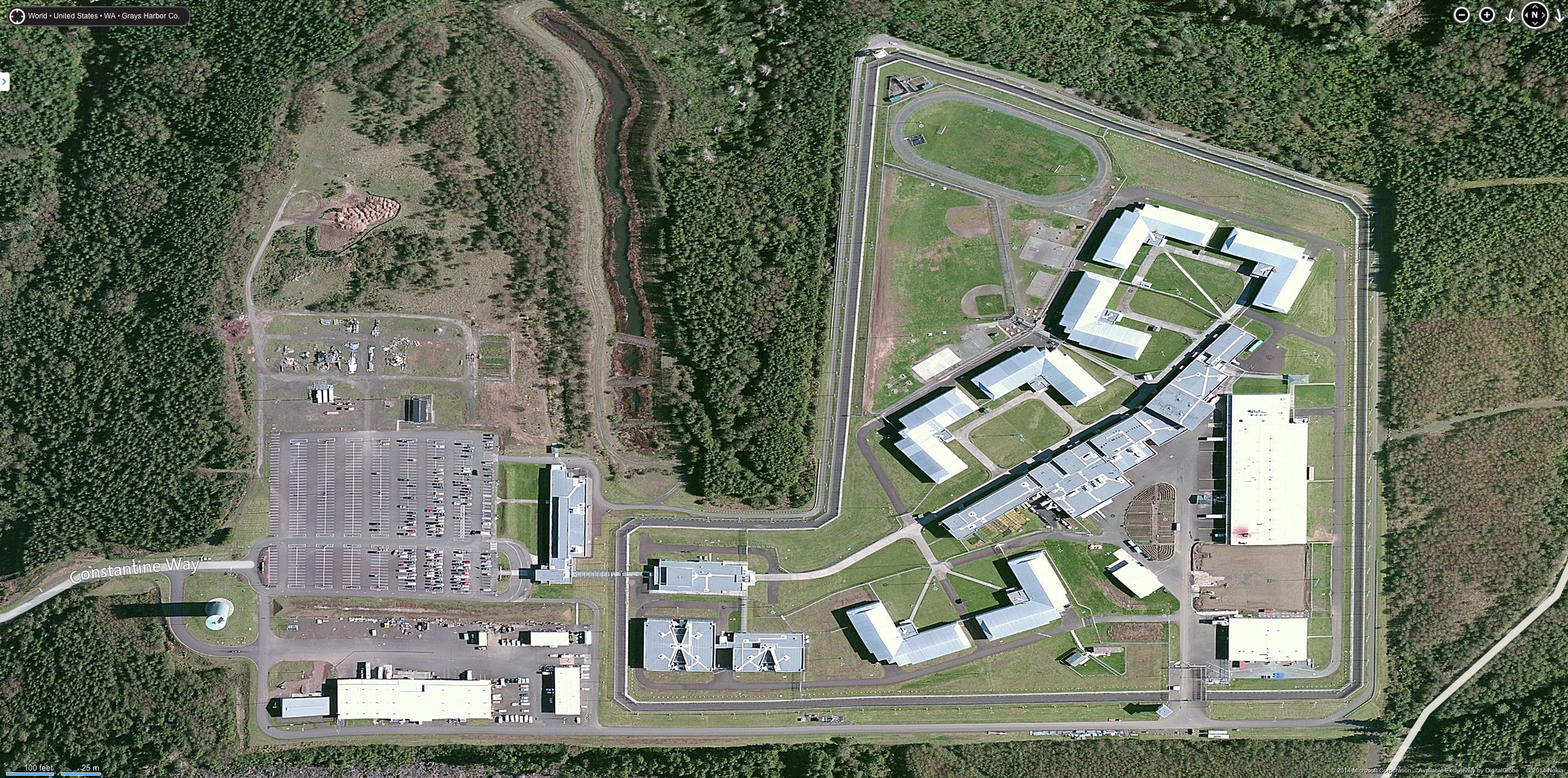
Figure 5: Aerial Photo of the Corrections Facility from the West
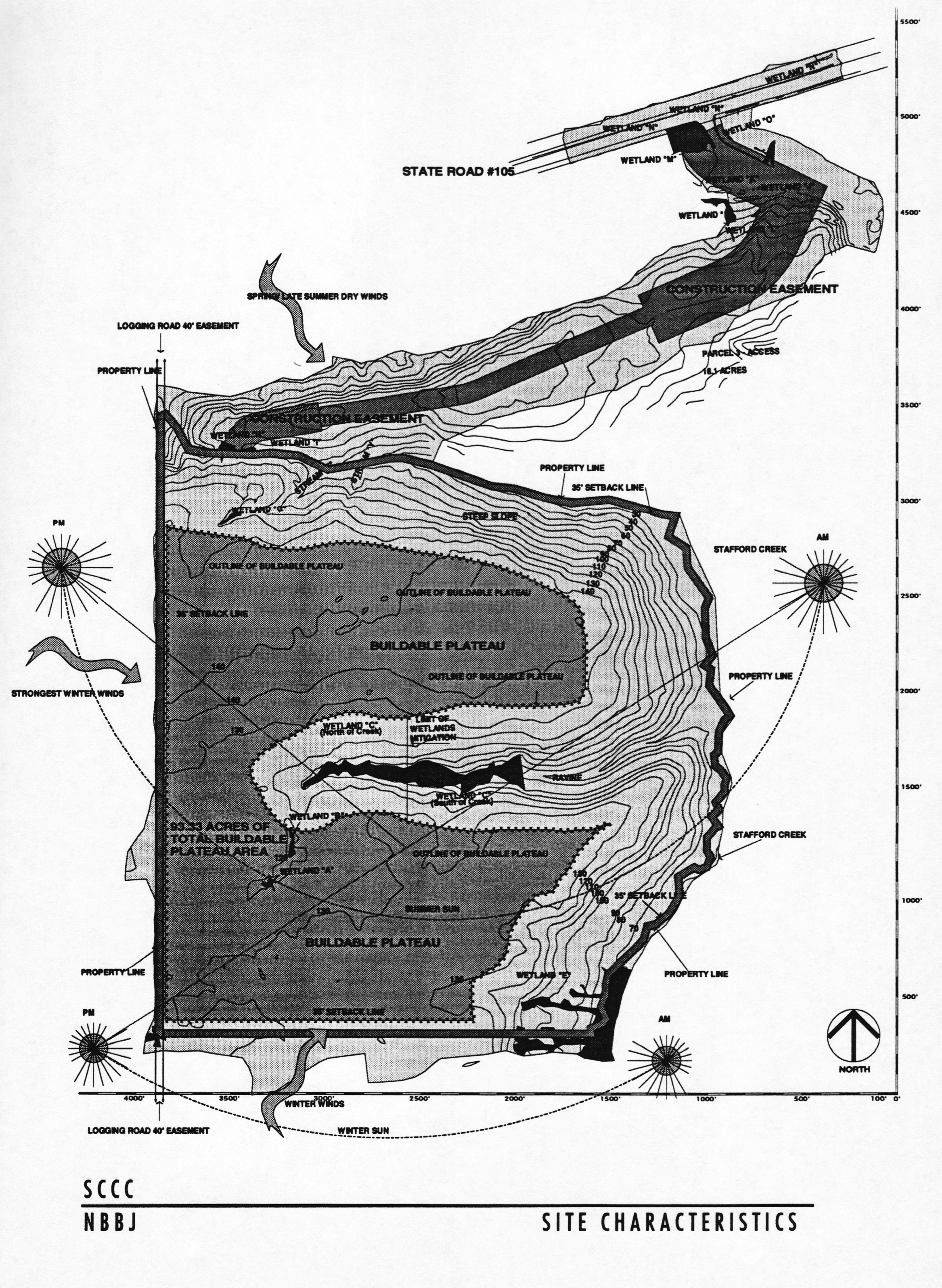
Figure 6: Site Climatology Diagram





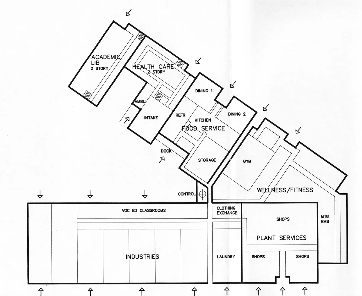
Conceptual Diagram for Inmate Services & Programs
The "mouth" of this series of interconnected inmate program buildings is the "feature" of Scheme B4 that solved so many design problems that irked rectilinear schemes that were characteristic of earlier concepts rejected by the Department of Corrections Team. The benefits of this simple device to self segregating the "deliveries" to the facility from the "internal circulation" of the inmate population were a breakthrough of the concept which retained this quality right through to construction.
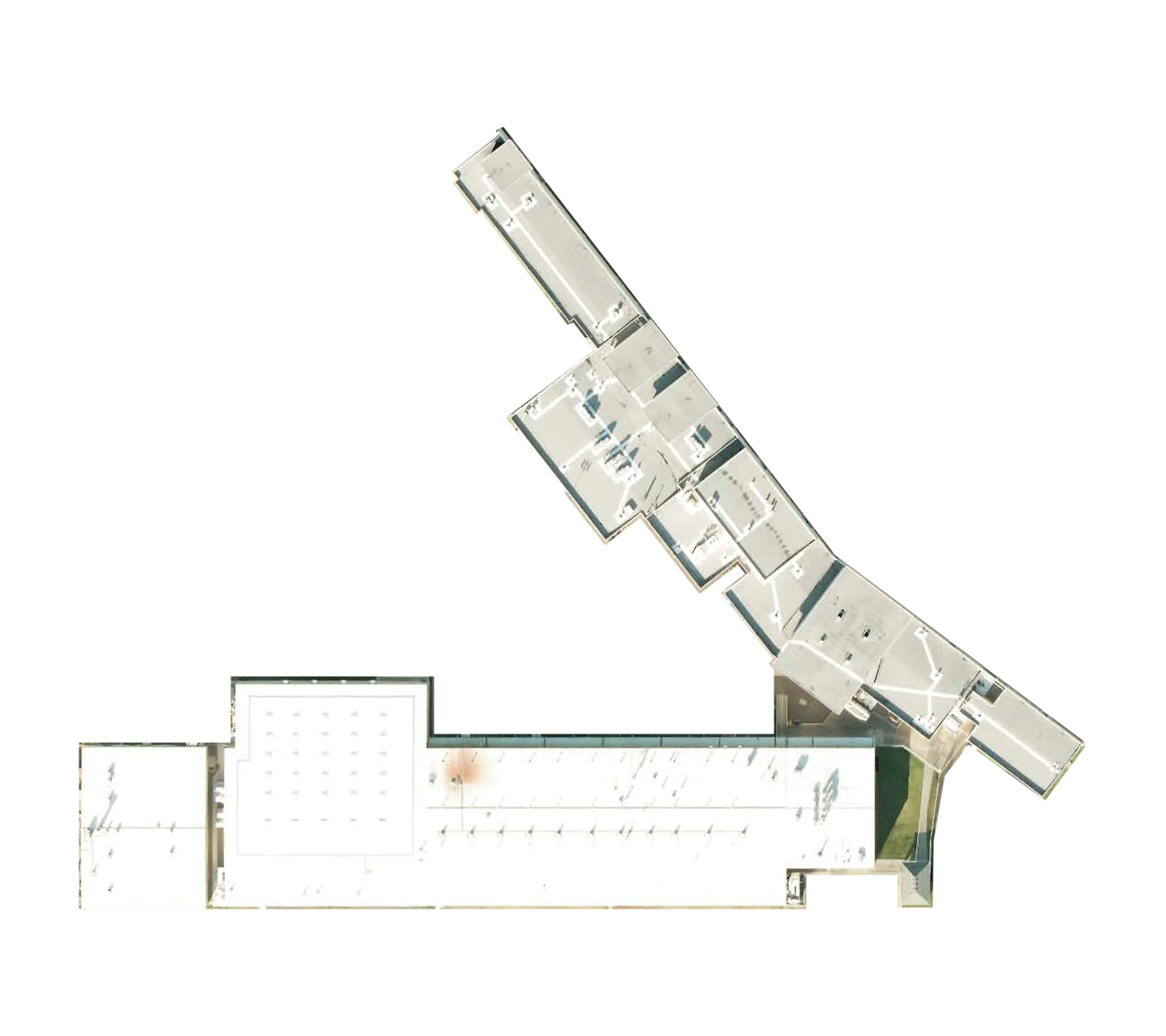
Constructed Diagram for Inmate Services & Programs
Over the eighteen months of design and documentation, the feedback from the department of corrections further enhanced the "mouth" of the facility where the intake of new inmates, industries materials, ambulance, and food are all protected from visual or physical access by inmate traffic. This aspect of the inmate programs buildings configuration survived and evolved over many many months of schematic and design development phases of the project.

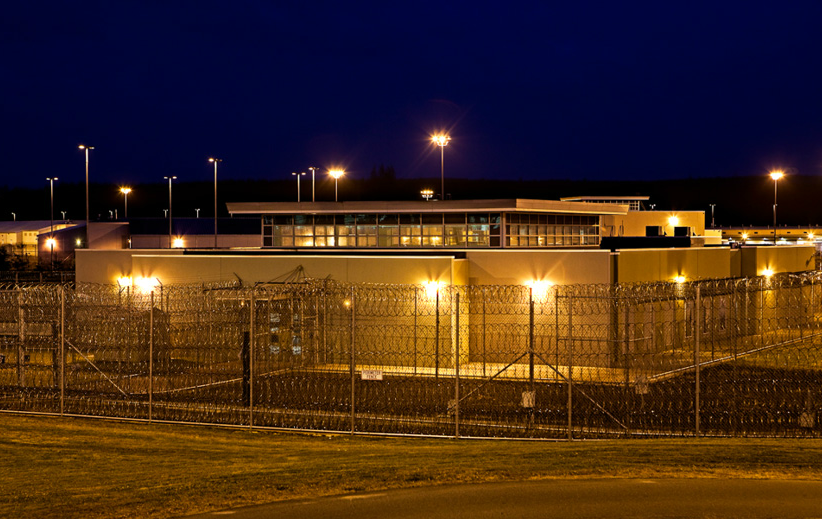
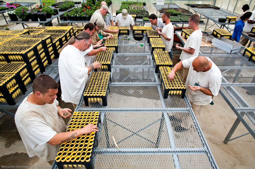
From CNN: The organic vegetables travel a short distance from the well-tended garden to the table where they are eaten. Waste is carefully picked through and recycled, saving thousands of dollars. The close-cropped lawns are maintained by push mowers to cut down on carbon emissions and gas expenses. This is not some new designer eco-hotel where the rich and environmentally conscious can be pampered free of guilt. It's a prison. At the The Corrections Center, a few yards from the garden where strawberries and cucumbers grow looms a tower where guards watch inmates, high-powered rifles at the ready. A jungle of razor wire surrounds the facility.
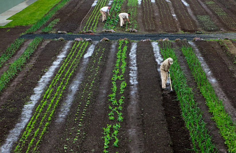
When ecologist and professor Nalini Nadkarni first pitched the idea of prisons going green she didn't know how her proposed partners -- convicted criminals -- would respond. "Would they be full of tattoos with shaved heads? How would I connect with them?" Nadkarni recalled thinking, "They turned out to be the easiest audience to connect with. They have been so open so wanting to learn, so desirous to connect with the environment." With the programs that Nadkarni and other instructors from the Evergreen State College helped devise, hundreds of inmates not only have a positive impact on their prison environment but on the world beyond the walls confining them.


Inmates are restoring local protected but disappearing grasslands by hand planting thousands of seedlings in a prison greenhouse. This has helped me get my head back on and stay out of trouble. --inmate Tyson Prater Inmates at another state prison raise an endangered species of frog. The inmates work for less than a dollar an hour and as a result of their incarceration are able to take on time consuming and labor intensive projects. But the inmates are not just doing grunt work.


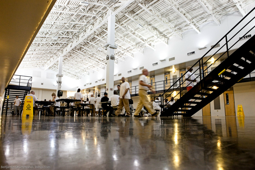
"They are observing, taking notes, what they are doing is science," she said. Both ecologists and prison officials have been surprised by the passion and seriousness of the prisoners involved with the project, Nadkarni said. The inmates raising the frogs had better results than a group of scientists conducting a similar project in a lab. Nadkarni coauthored a scientific paper with one inmate. Another surprise has been the savings involved in the project.
"In the beginning a lot of the motivation is just around the money," said state deputy director Dan Pacholke, who green-lit Washington's first environmental programs behind bars seven years ago. Just at Stafford, officials saw savings of close to $200,000 a year just byrecycling trash instead of paying to have it hauled to a landfill. The benefits have gone far beyond fiscal savings, Pacholke said. "When you get into it you find there's a lot you can do to get inmates involved in other programs whether it be gardening or recycling. Over time you are trying to connect offenders with something that is meaningful or with purpose that they feel is valuable and give them activities that offset the costs of prisons themselves." Pacholke said officials have seen a drop in violence among prisoners participating in the program and the state plans to expand the program from four prisons to all 13 institutions. Inmates volunteer for the program and can't have any infractions or they get kicked out. Inmate Toby Erhart, halfway through an 18-year sentence for rape and incest, said his work in a prison garden allows him to contribute something to society. "Just because I am incarcerated it doesn't have to be a negative thing," Erhart said. "I see a lot of people being affected negatively and it doesn't have to be like that. I look forward to coming to work ever day. How many people can say that on either side of the fence?" As he added scraps of food from the prison mess hall to a compost heap, inmate Tyson Prater said he too feels fortunate. "This has helped me get my head back on and stay out of trouble," he said. Prater said he is hoping to pick up the skills that would allow him to work for the U.S. Forestry Service when he is released from prison in three years. Prison officials say that the program prepares inmates to work in certain sectors of the growing green jobs field. It also makes them environmentally conscious citizens who know about recycling, sustainable farming and conservation when they are released, they said. Pacholke said the greatest dividends the program may provide may actually take place outside of prison. "[About] 97 percent of the people in here are getting out some day and are going to ride next to you or I on inter city transit," he said "So what's the experience you want them to have when they come back out to the communities?"

