Stanford M.E. Lab DD
Project Summary:
Architecture Firm: MBT Architecture, Seattle
Client: Stanford University, College of Mechanical Engineering
Date of Construction Completion: 2001
John Millard's Role: Project Architect for Combustion Science Laboratories (High Pressure Combuster Lab & Engine Laboratory)
Duration of Design Effort: Schematic Design- November 1999, Design Development- May 2000, Construction Documentation- October 2000
In a laboratory environment, the coordination of equipment, casework, services distribution and penetrations with the layout & fabric of the building has always required the focused effort of MBT lab architects. With improvements in computer processing speed we are now able to carry out our work three dimensionally from conception to construction and now have systems in place in our Seattle & San Francisco Offices to communicate the following enhancements to our workflow.
· We are now able to hand over electronic 3d files which offer a post-construction role to facilities management as an object-oriented three dimensional database including all casework, interior partitions, equipment, furniture, and architecturally driven flexible services distribution systems. We collaborate with casework manufacturers, contractors and engineers in the exchange of data to this end. In the event of reconfiguring a lab for new workflow, these files can make this process the electronic equivalent of “rearranging” the lab rather than a total TI redraw.
· The advantage of producing plans, sections and interior elevations of detailed spaces such as a laboratory by cutting through a “3d virtual building” and providing the required information in two dimensions is that changes, once made to the model, are automatically updated in the schematic phase 2d drawings.
· User visualization of spaces and usability of working environments can be a challenge when reviewing two-dimensional plans. MBT offers clients such as Stowers Medical Research the service of viewing space by animation. This is a direct result of having the design developed three dimensionally. Alternatively, users may receive VRML files of their spaces from the web based project site and navigate freely through space using a web browser plug-in.
· By constructing “intelligent” drawings, specification of the building quality can be derived directly from the model and incorporated into the specification, schedules, and inform the cost estimation process more completely.
The status of these drawings is 90% for DD – excluding any detail references, section references, dimensions, wall-mounted fixtures such as those shown on the plan for these spaces, as well as more detailed notes which should probably go on larger scale sections anyway.
Prior to drawing sheets A401, A512, A513, there was an investment of time to carry out the following tasks:
8/6 – 8/9 – Convert 3D models to 2D acad files/ 14.5 hrs
8/3 – 8/4 – Transmit HPC report to consultants via UPS/ 8 hrs
7/28 – 8/2 – Complete the Pagemaker report/ 30 hrs
7/27 – Add additional 3D components to HPC model based on the late user info/ 8 hrs
7/26 – Transmit Engine lab report to all/ 8 hrs
7/15-7/22 – Complete Engine lab Pagemaker report/ 30 hrs
6/28-7/14 – Construct Combustor model/ 53 hrs
6/14-6/25 – Construct Engine Room model/ 57 hrs
Status of this work is the
· AH 3-D models are pre-user conf 8/19
· Mounting heights shown for HPC on sheet A401 are subject to Gaynor Engineers (or someone else’s) correction of mechanical scheme. Defects of currently show design—
· All supply air ducts conflict with crane structure.
· Return air duct conflicts with cable trays and power feeds and piped services.
· Penetrations through fire-rated west wall create unnecessary acoustical and fire damper conditions and excessive duct length – Access to HPC Lab with mechanical ducts should be through north wall over the door as shown in report transmitted to Gaynor on 8/4.
· HPC self-aspirating exhaust pipe conflicts with travelling bridge beam (again ignoring 8/4 report recommendations as well as telephone conversation with Grant Wong on 7/7/99.
· HPC s-a-e-p also breaches 1 hour fire wall (twice) on west side of occupancy separation.
· In general, there are far too many F.R. penetrations.
· I have not yet received a set showing other services…will they be showing all services described in my report? If not, who will be showing them at C.D. stage?
· Users need to by off on cable tray clearance shown in 2/A513 where they throat down to penetrate control room wall.
· The above penetration conflicts with display panels in control room (see 1/A513). We need direction on how to resolve this conflict.
· Brian Carilli suggested moving the sprinkler pipe above the exhaust pipe at the 8/18 meeting. Done. But as shown in 3/A513, stub ends may still be necessary to clear obstruction of exhaust pipe per code.
· Fish eye diffusers in F. R. ducts and HPC ducts should be specified to provide effective air.
· Wall-mounted outlets, etc., which are shown on plan may be drawn on int elevs for clarity but will be replicated and all other outlet info. Missing from other in t elevs.
· Section indicators should be drawn on plans and sections.
· ½” sections (partial) should be drawn through complex cond.
· Details including bracketry, acoustical penetrations, seismic, drywall connections to unistrut, miscellaneous metal, window and door details will all be necessary in thse spaces – Control Rooms will require additional detailing for equipment mounting, combustible gas penetrations as well as others.

Figure 1: Shaded area indicates JBM scope- Design Combustion Science Labs in New Mechanical Engineering Building
The New Stanford University Mechanical Engineering Building by MBT Architecture is a two story concrete structure that required a team of six architects at MBT to participate in the design and documentation. John Millard was responsible for the shaded area on the first floor plan known as the Combustion Science Laboratories. John travelled frequently to Stanford to meet with Stanford Professors involved with the programming, equipment requirements and the ergonomic considerations of the client team.
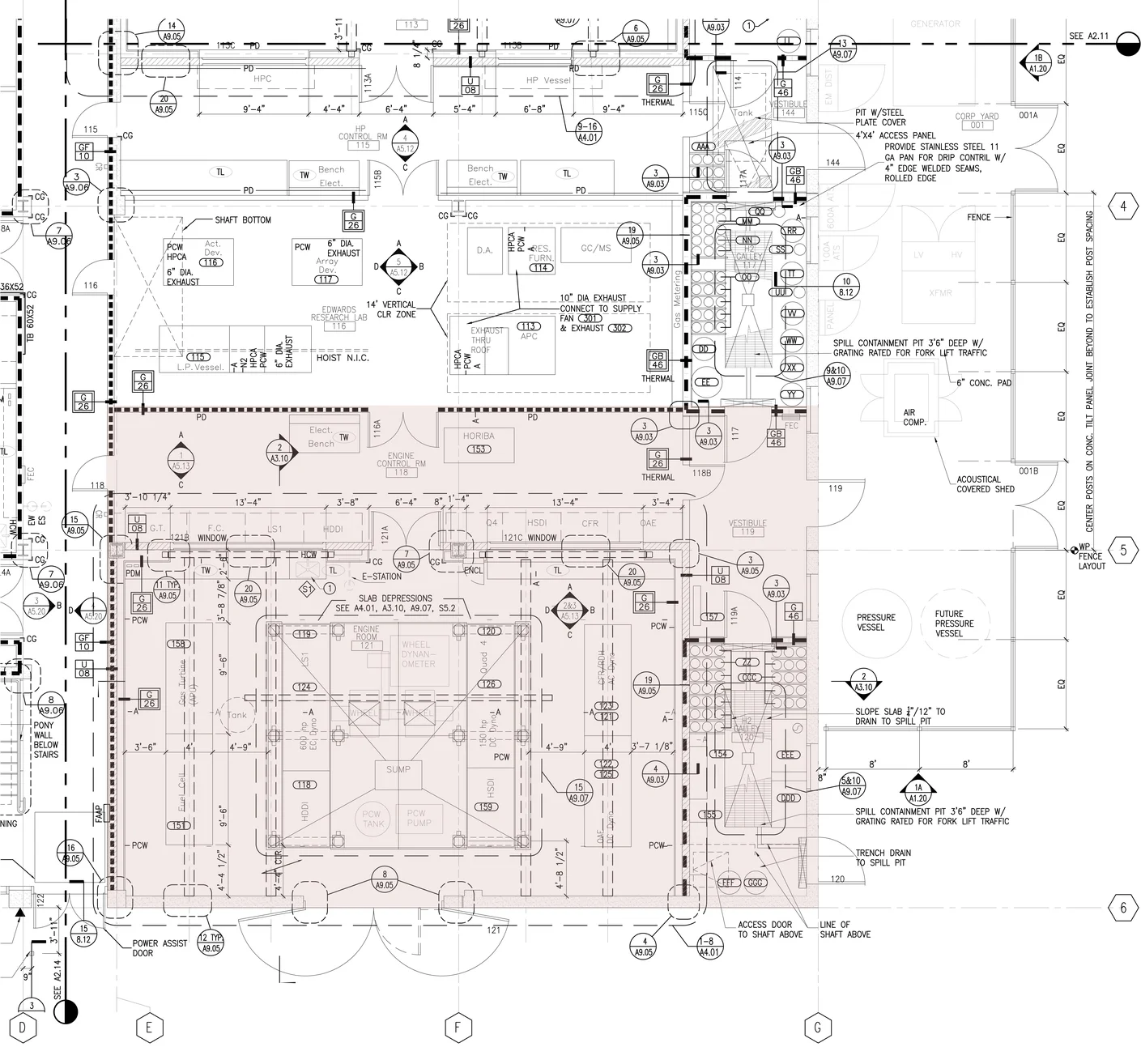
Figure 2: Shaded are indicates Engine Lab and Control Room Area- Drawing by John Millard
The Engine Lab and its associated control room in the College of Mechanical Engineering are shown shaded in the plan above. To the right shaded area is the Hazardous Substances Gallery where various combustible gasses and liquids triggered fire code requirements that John Millard was also responsible for conferencing with the AHJ in Palo Alto, California.
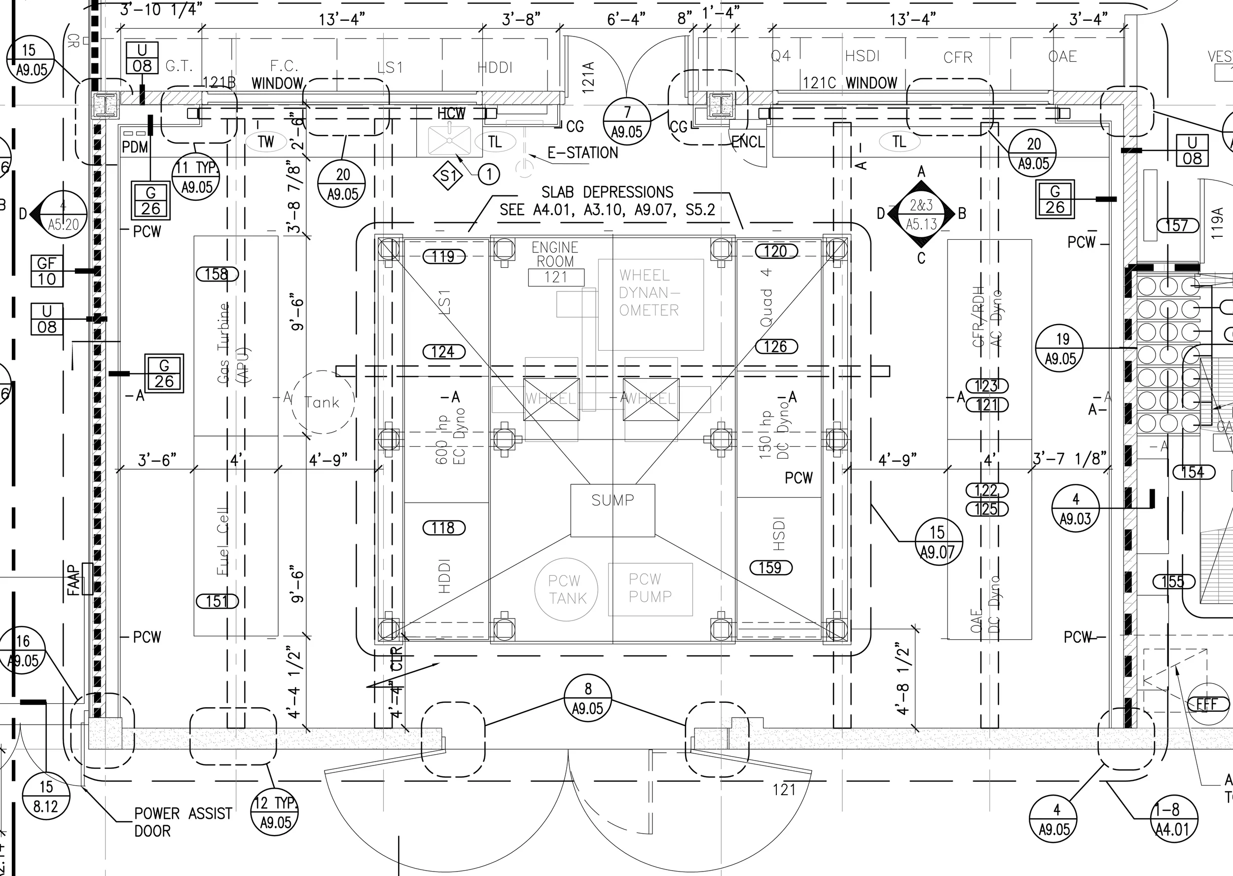
Figure 3: Plan of Engine Lab- Base Isolation for the Dynamometer prevents vibration from engine testing to be telegraphed into the building structure. Drawing by John Millard
By far, the most noise produced by research activity in the building is in the Engine Laboratory where both sound from combustion engines and vibration from entire road vehicles atop the dynamometer might otherwise be transferred into the rest of the building spaces were it not for the acoustical engineering design of Acoustic and Vibration Solutions.

Figure 4: Sheet A3.10- Section Through Engine Lab. Drawing by John Millard
Design Development of the Engine Lab required an architect to unify and coordinate the requirements of each engineering discipline for the space to be constructible. This required the cooperation of the Structural, Mechanical, Electrical, Acoustical, Plumbing, Illumination, and Code Compliance teams to agree on the single mddl produced by John Millard in order to coordinate each discipline's component contribution to the whole design. Forward coordination with the mechanical electrical contractor also was helpful.

Figure 5: Enlarged Section from A3.10- Drawing & Design Coordination by John Millard
The Engine Lab required a plethora of overhead services in order to meet the requirements of the faculty at Stanford's College of Mechanical Engineering. These overhead services were challenged by the requirement of 3 traveling bridge beam cranes that move across the entire work area.

Photo 1: Construction Administration of the Engine Lab required interface with MBT Architect John Millard. Photo by John Millard
Electrical and Mechanical Contractors often experience coordination conflicts on projects where the architect failed to coordinate the engineering designs. These conflicts can often drive up the cost of construction and lower the confidence in a set of drawings. In this case, the complexity of the layers of overhead services including diesel lines, high octane gasoline lines, hydrogen lines, exhaust air, supply air, power and communications, as well as sprinklers, dedicated exhaust, process chilled water, and lighting- all attracted the undivided attention of the contractor to the architect's coordination drawings for this lab, and they were not disappointed.

Figure 6: Enlarged Section from A3.10- Drawing & Design Coordination by John Millard
In this section, the slab depressions required to contain (from left to right) a) the possible future sprinkler water in the hazardous substance galley, and b) the dynamometer for vehicular movement management- both show a depression in the floor slab that headed the list of slab depressions in the entire building that were coordinated by John Millard.

Figure 7: Interior Elevation from Sheet A5.13- Drawing & Design Coordination by John Millard
This interior elevation shows penetrations in the acoustical envelope of the room for the traveling bridge beam crane rails, control room windows and other openings that risked transference of noise into the lecture spaces and labs on the second floor. The detailing of these penetrations greatly reduced the noise.
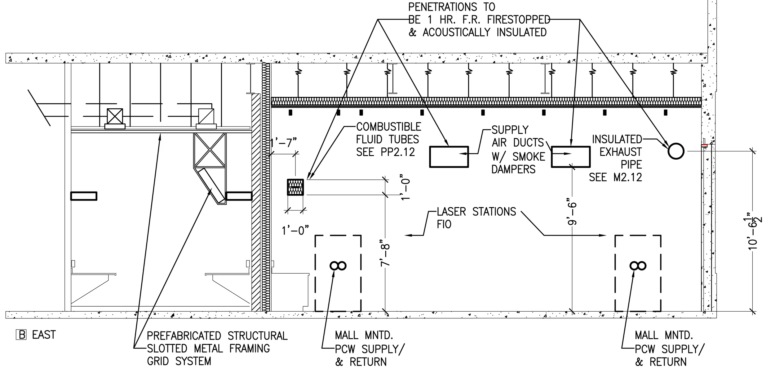
Figure 8: Interior Elevation/ Section from Sheet A5.13- Drawing & Design Coordination by John Millard
Each wall penetration had both acoustical and fire insulation requirements in order to maintain the fire/ occupancy separation that enabled the engine lab to be permitted to be constructed. These protective measures that stop the spread of fire, smoke and noise. This elevation also indicates the plumbing services that exist inside the wall as well as other components that with penetrated the wall or were mounted on the wall.
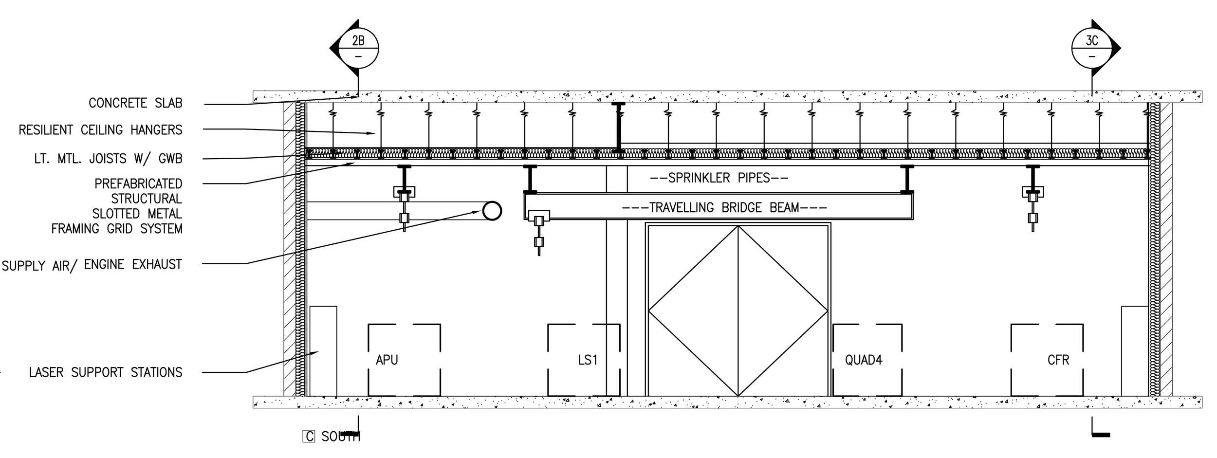
Figure 9: Interior Elevation from Sheet A5.13- Drawing & Design Coordination by John Millard
The traveling bridge beam that traverses the center of the room is designed to carry heavy loads such as engine blocks over modest distances inside the room from the double cargo doors in the south wall where a vehicle may access the room and deliver an engine for testing inside the engine lab. The presence of this crane, as well as the linear cranes flanking the traveling bridge beam dramatically reduced the availability of overhead services solutions.
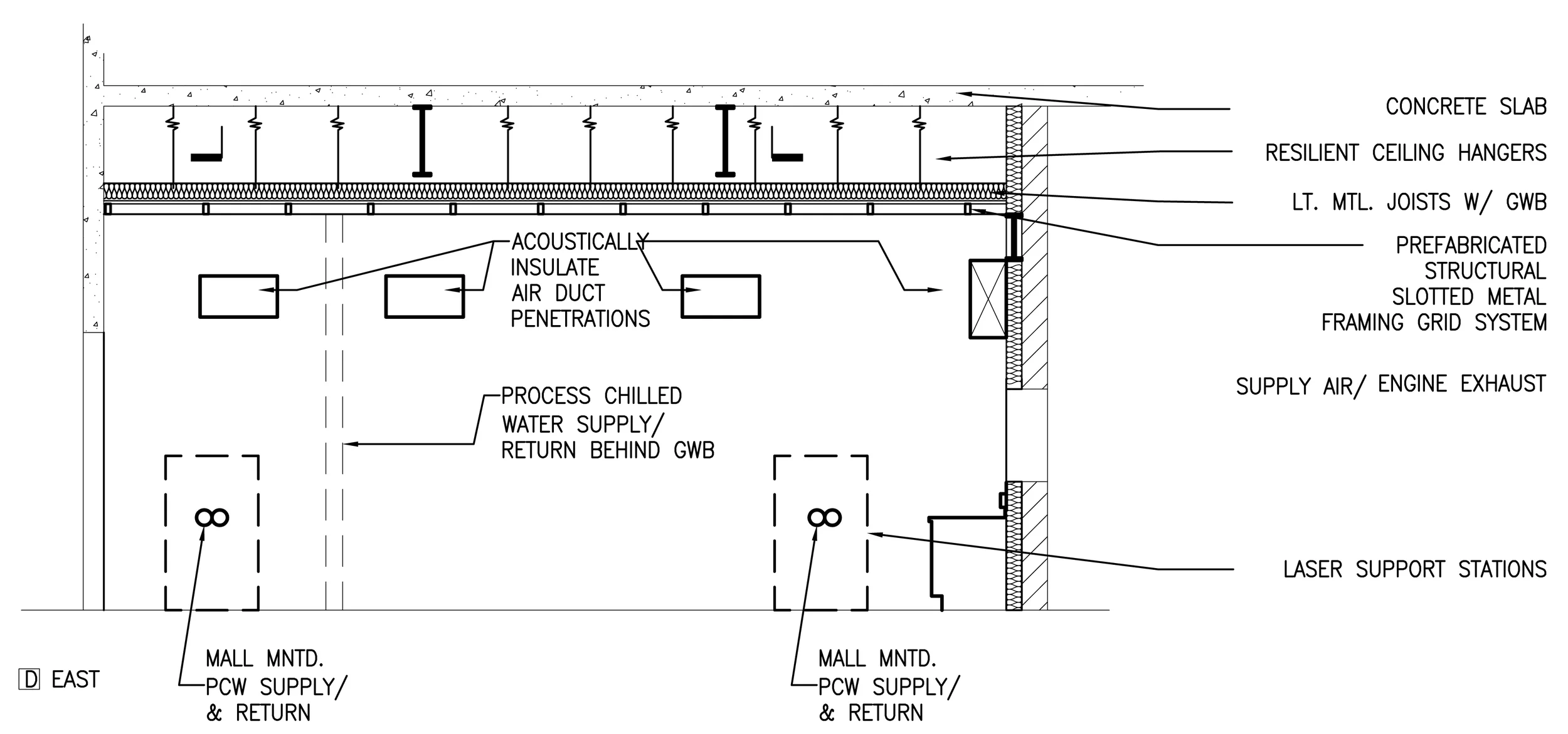
Figure 10: Interior Elevation from Sheet A5.13- Drawing & Design Coordination by John Millard
Each wall penetration had both acoustical and fire insulation requirements in order to maintain the fire/ occupancy separation that enabled the engine lab to be permitted to be constructed. These protective measures that stop the spread of fire, smoke and noise. This elevation also indicates the plumbing services that exist inside the wall as well as other components that with penetrated the wall or were mounted on the wall.

Figure 11: Interior Elevation from Sheet A5.13- Drawing & Design Coordination by John Millard
This interior elevation shows penetrations in the acoustical envelope of the room for the traveling bridge beam crane rails, control room windows and other openings that risked transference of noise into the lecture spaces and labs on the second floor. The detailing of these penetrations greatly reduced the noise.
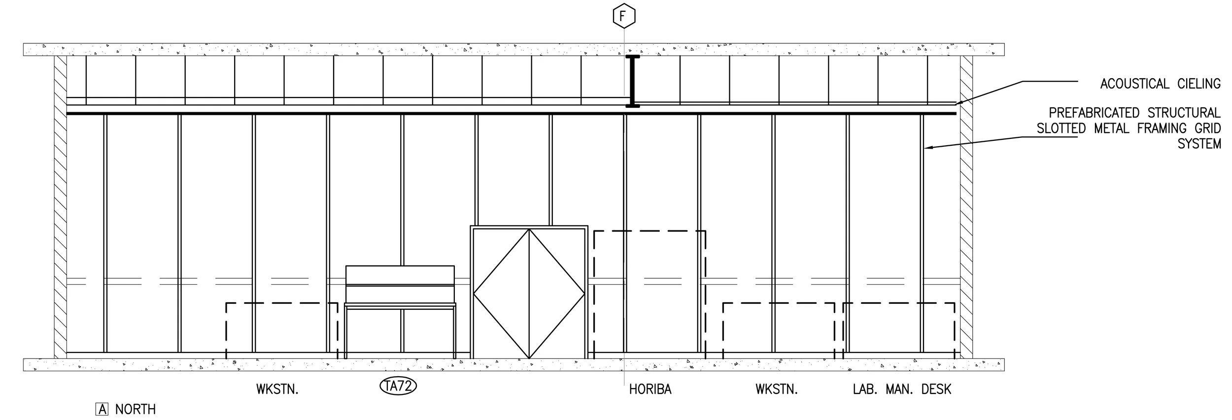
Figure 12: Interior Elevation from Sheet A5.13- Drawing & Design Coordination by John Millard
The interior of the engine lab control room was a flexible surface that required intermittent re-organization of user equipment.
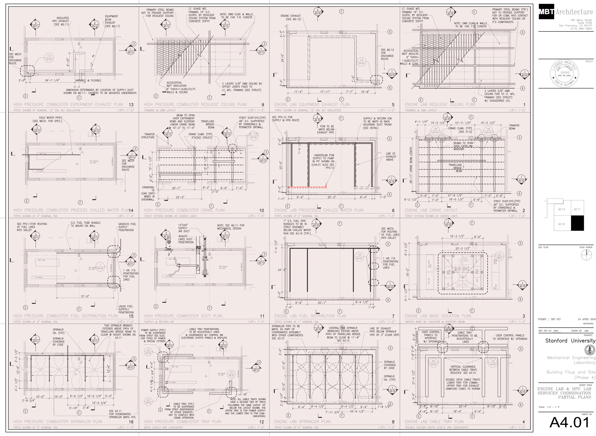
Figure 13: Sheet A4.01- Drawing & Design Coordination by John Millard
Shaded area indicates deign & documentation role and work product by John Millard.
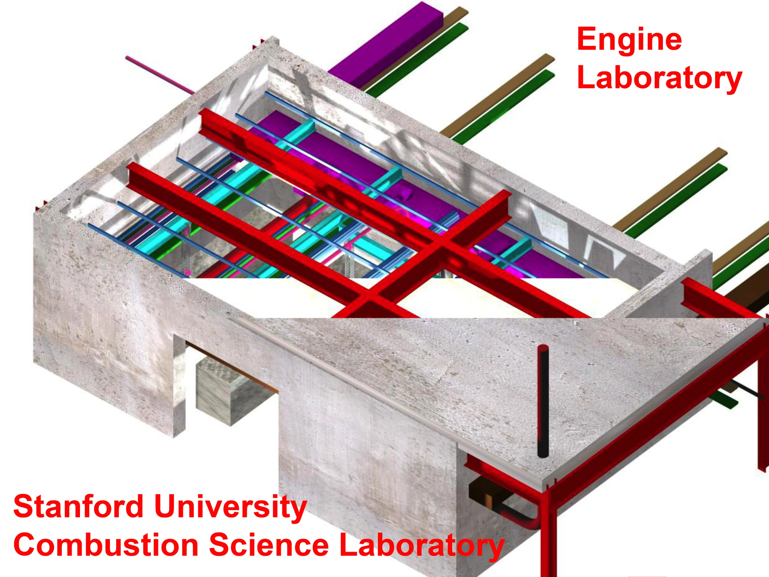
Figure 14: Engine Lab Coordination Model (ACAD ADT R3)- Drawing & Design Coordination by John Millard)
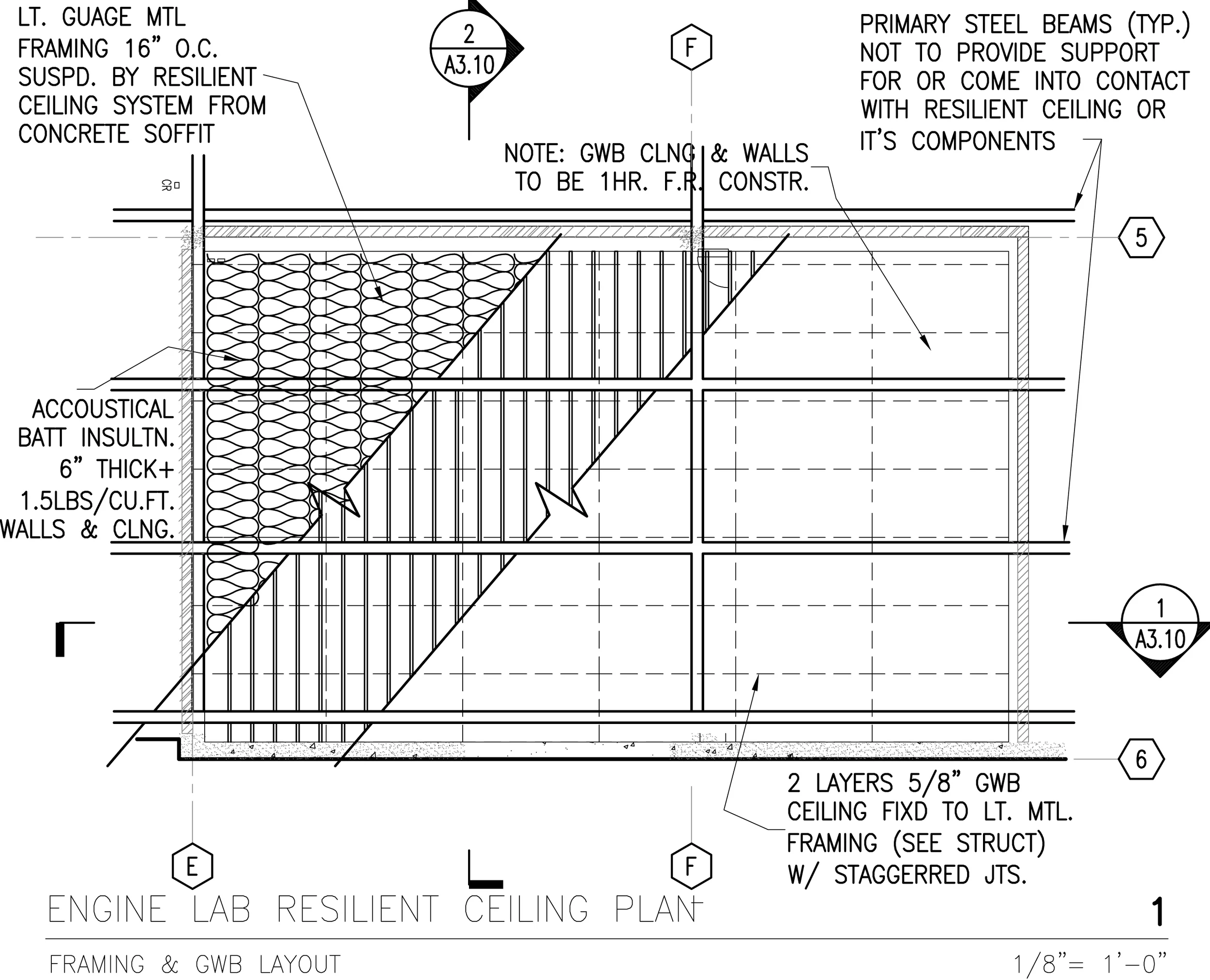
Figure 15: Enlarged Plan from A4.01- Resilient Enclosure Components
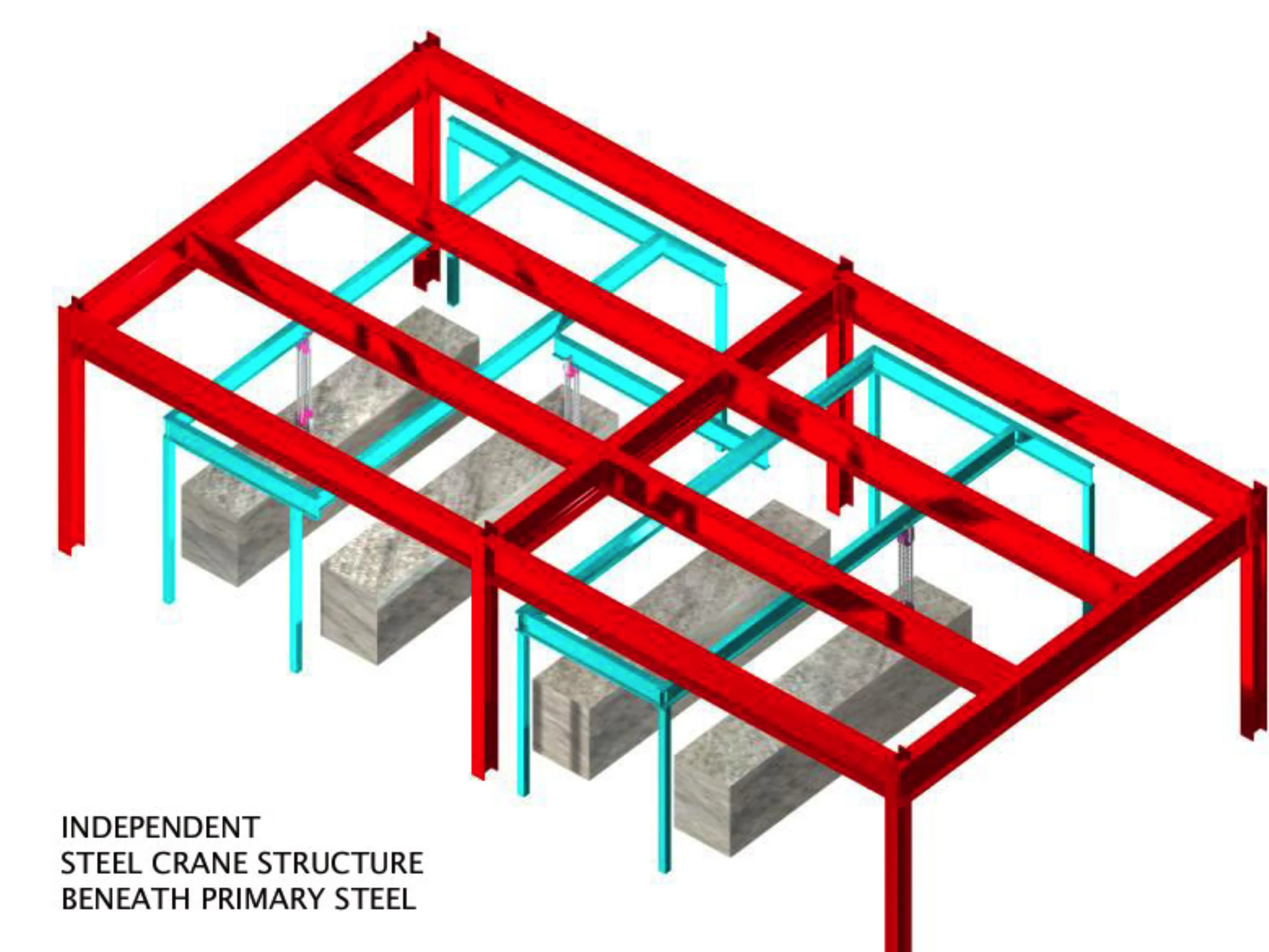
Figure 16: Engine Lab Coordination Model (Traveling Bridge Beam Crane)-
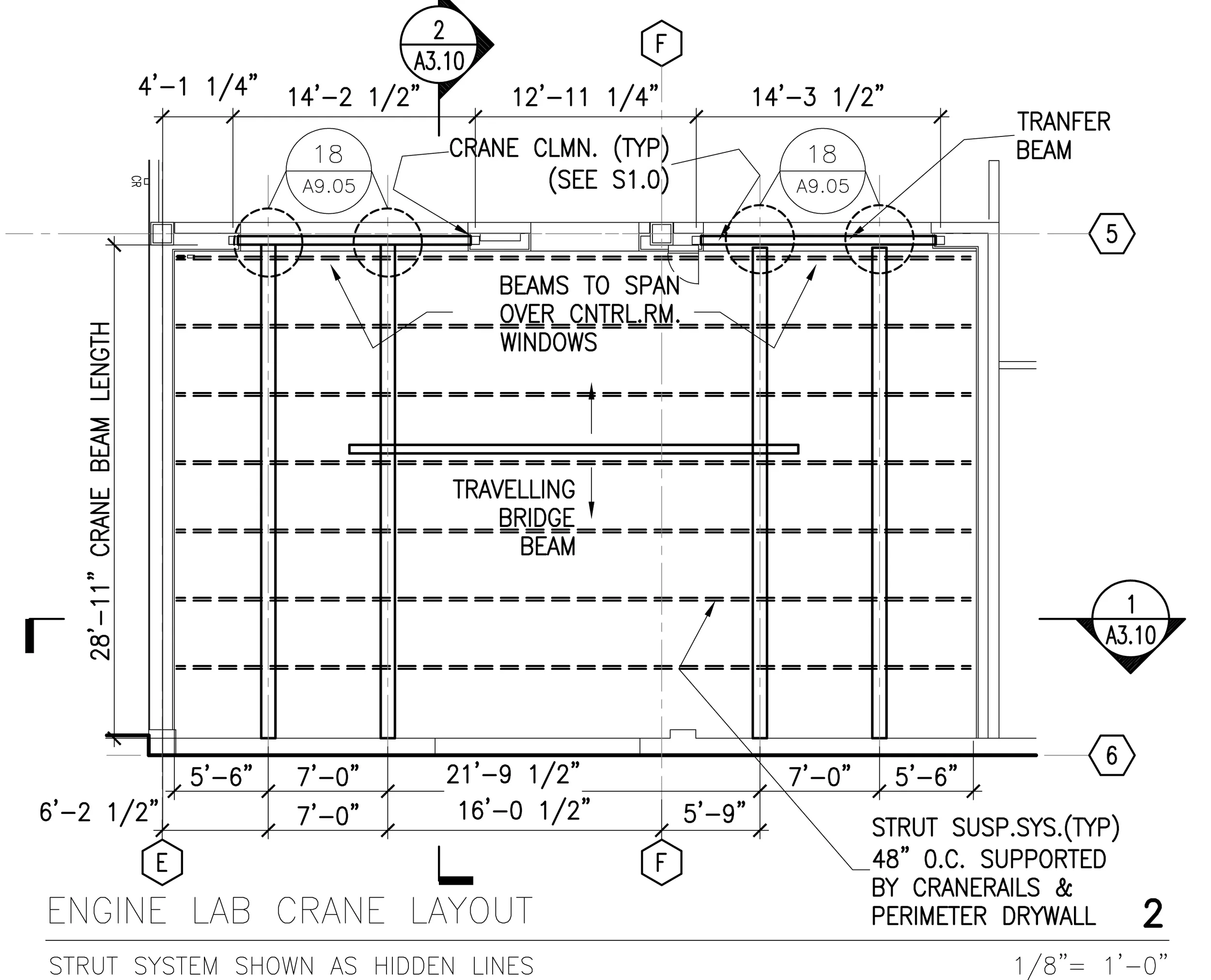
Figure 17: Enlarged Plan from A4.01- Crane Layout
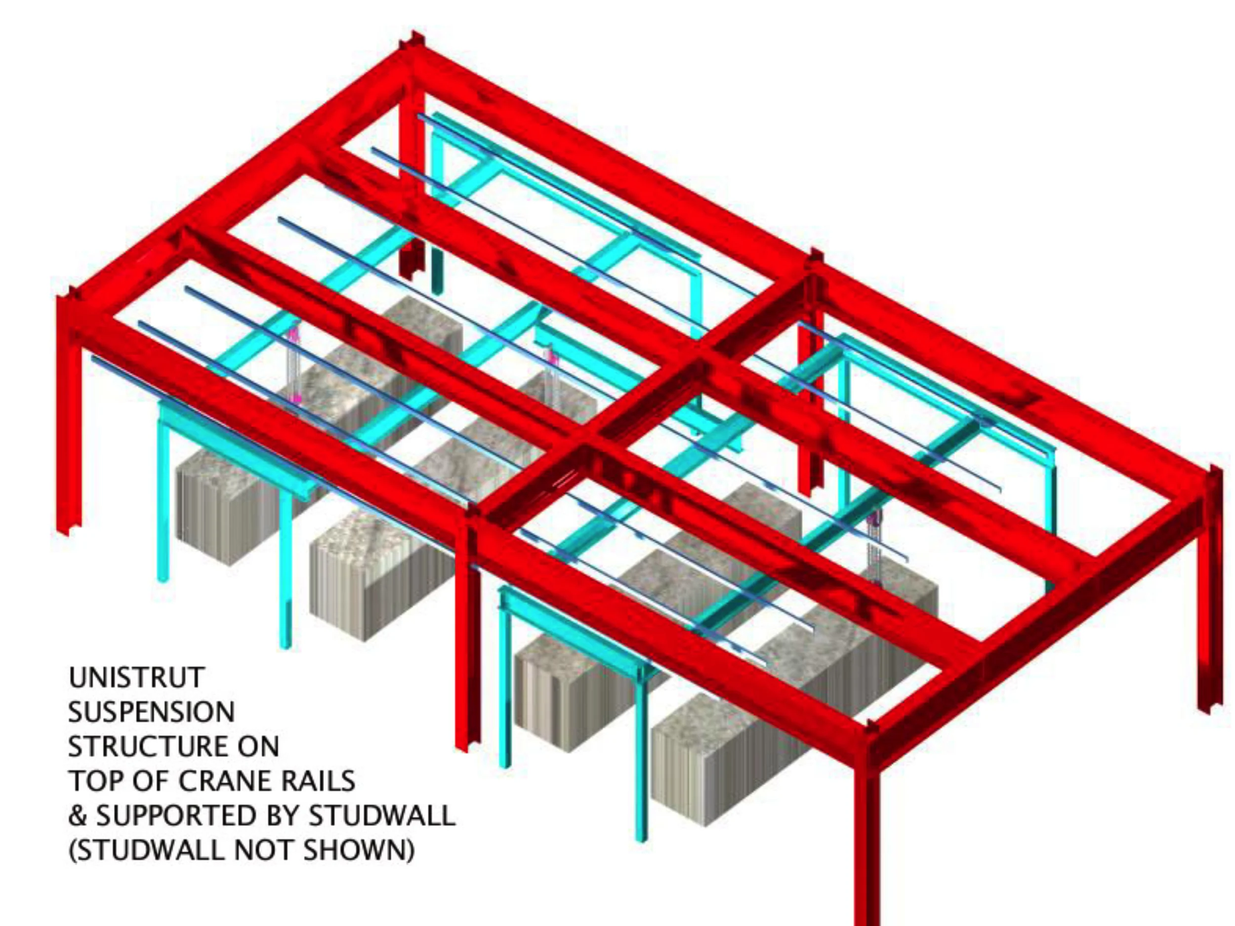
Figure 18: Engine Lab Coordination Model (Crane & Strut)
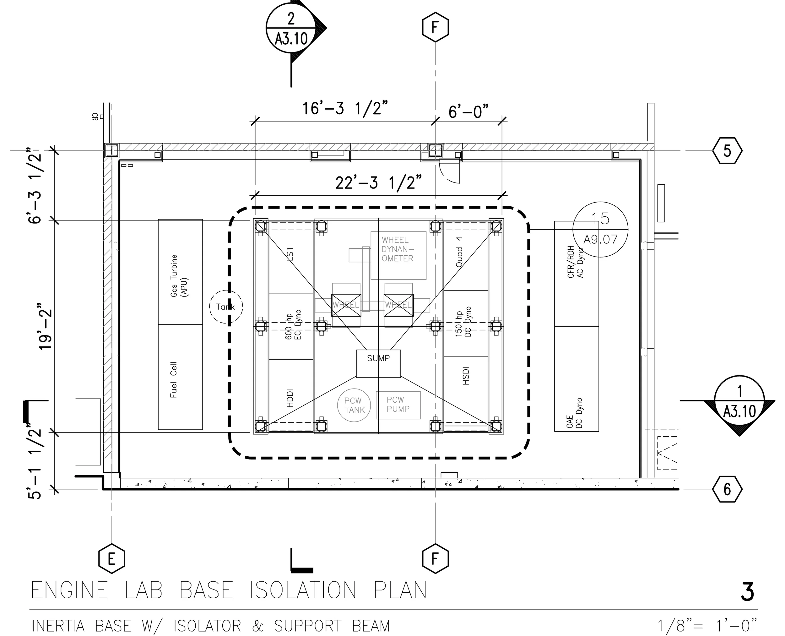
Figure 19: Enlarged Plan from A4.01- Base Isolation Plan for Dynamometer
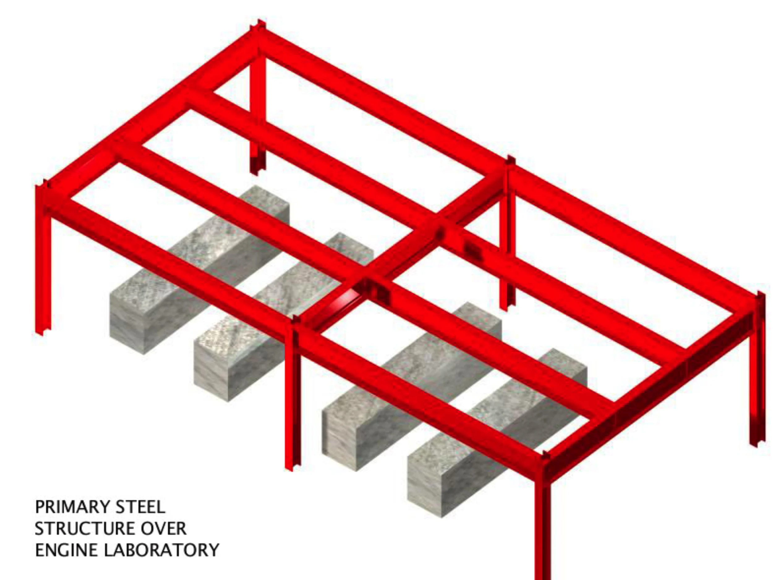
Figure 20: Engine Lab Coordination Model (Primary Bldg. Steel Structure)
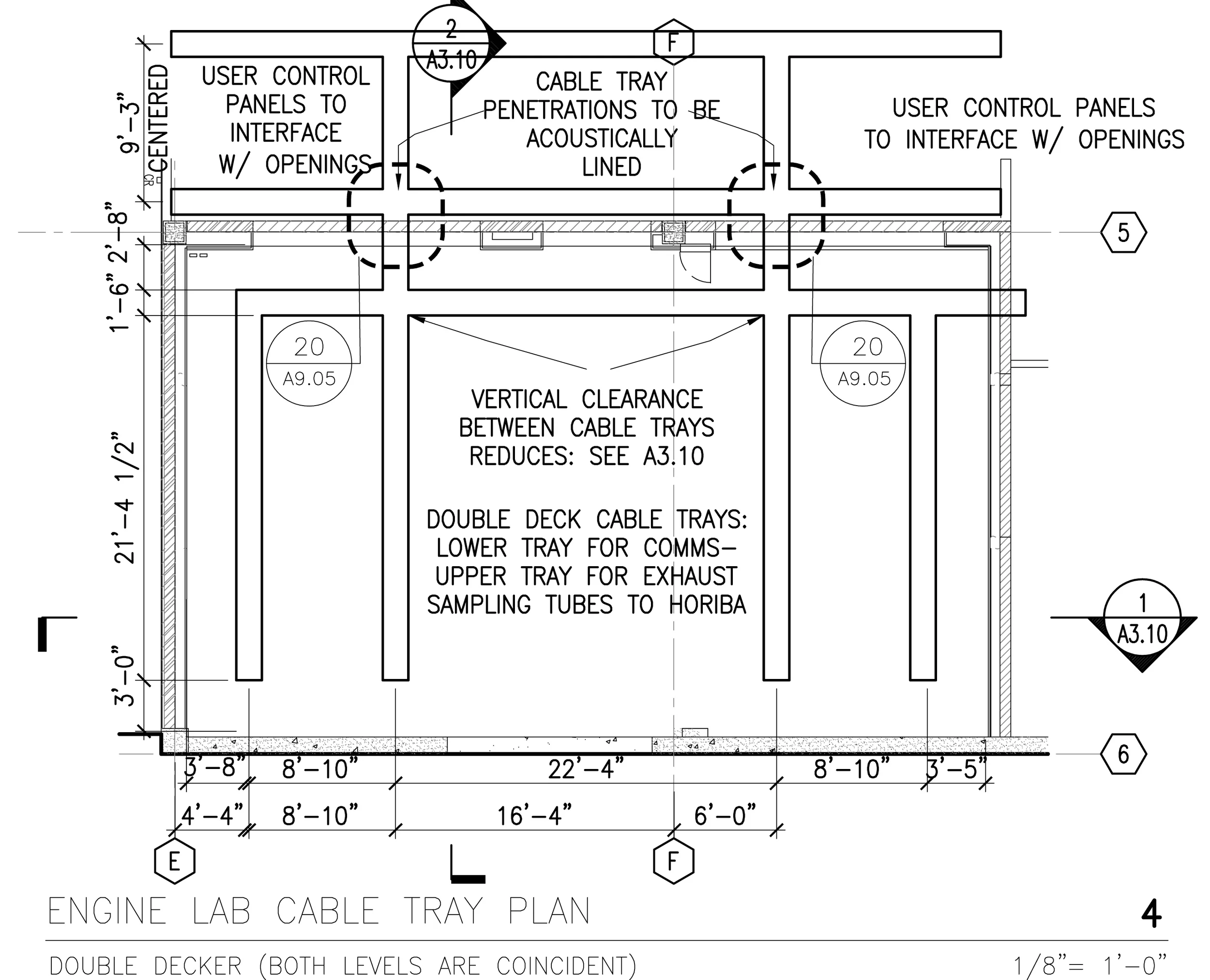
Figure 21: Enlarged Plan from A4.01- Overhead Power & Communications Distribution
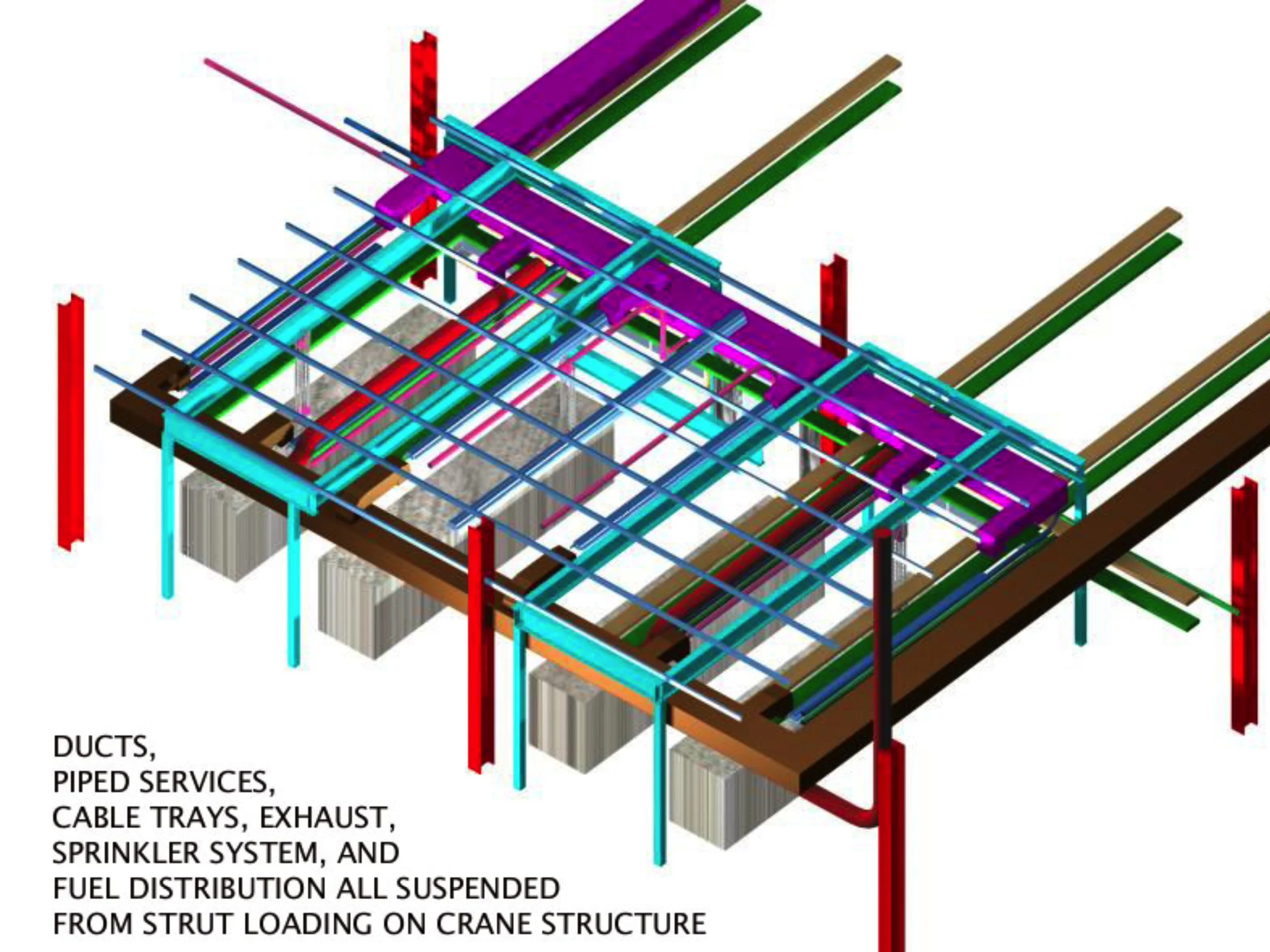
Figure 22: Engine Lab Coordination Model (Ducts, Plumbing, Cable Tray, Dedicated Exhaust, Sprinkler System, Fuel Lines, Strut & Crane)
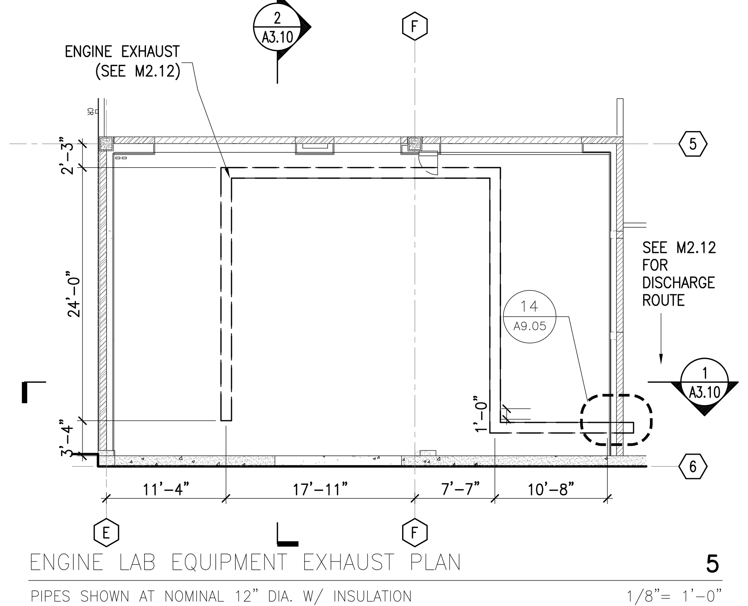
Figure 23: Enlarged Plan from A4.01- Dedicated Engine Exhaust

Figure 24: Engine Lab Coordination Model (Resilient Enclosure)

Figure 25: Enlarged Plan from A4.01- Room Supply & Exhaust Air Layout/ Process Chilled Water
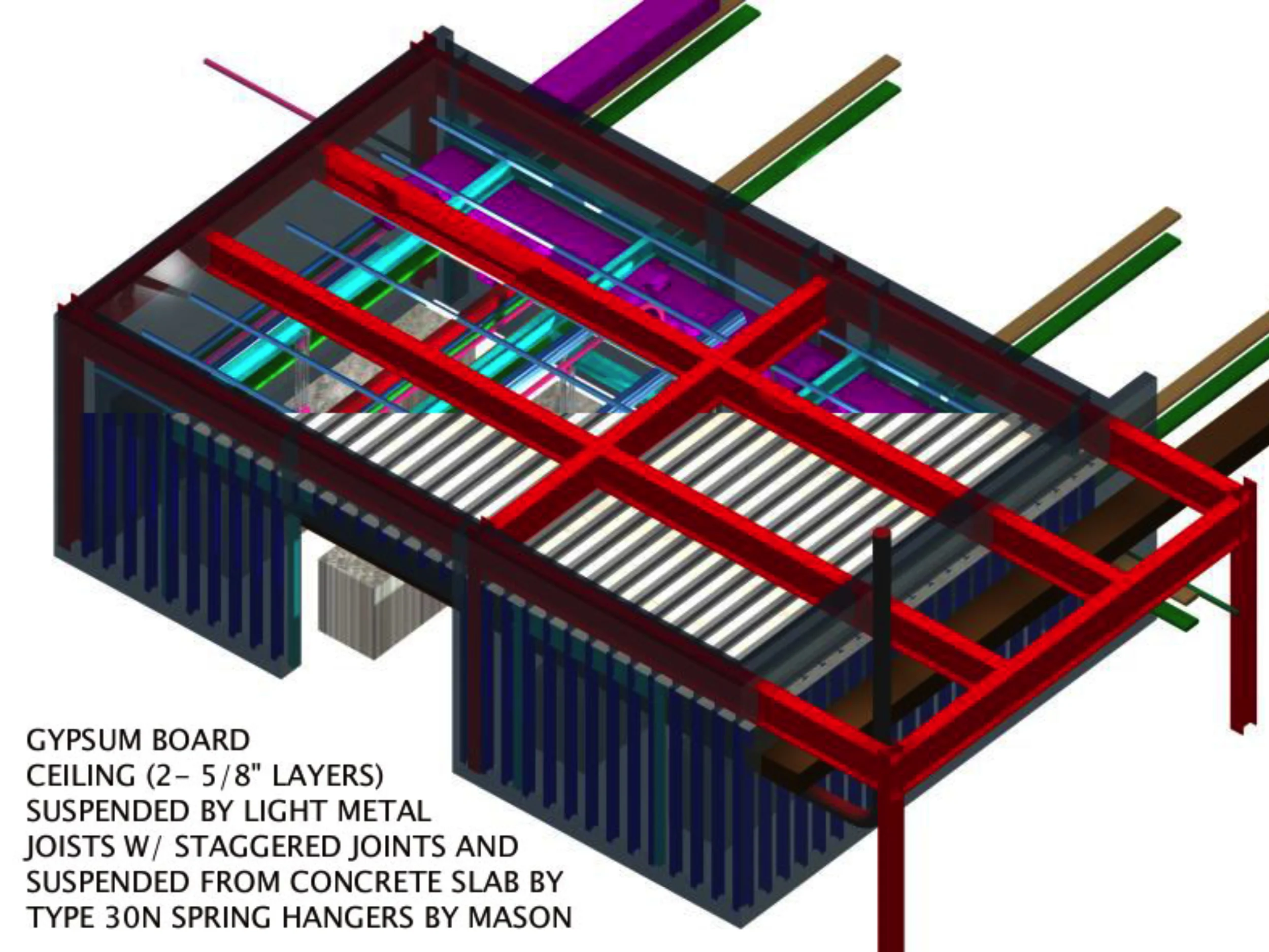
Figure 26: Engine Lab Coordination Model (Resilient Enclosure)

Figure 27: Enlarged Plan from A4.01- Fuel Line(s) Layout
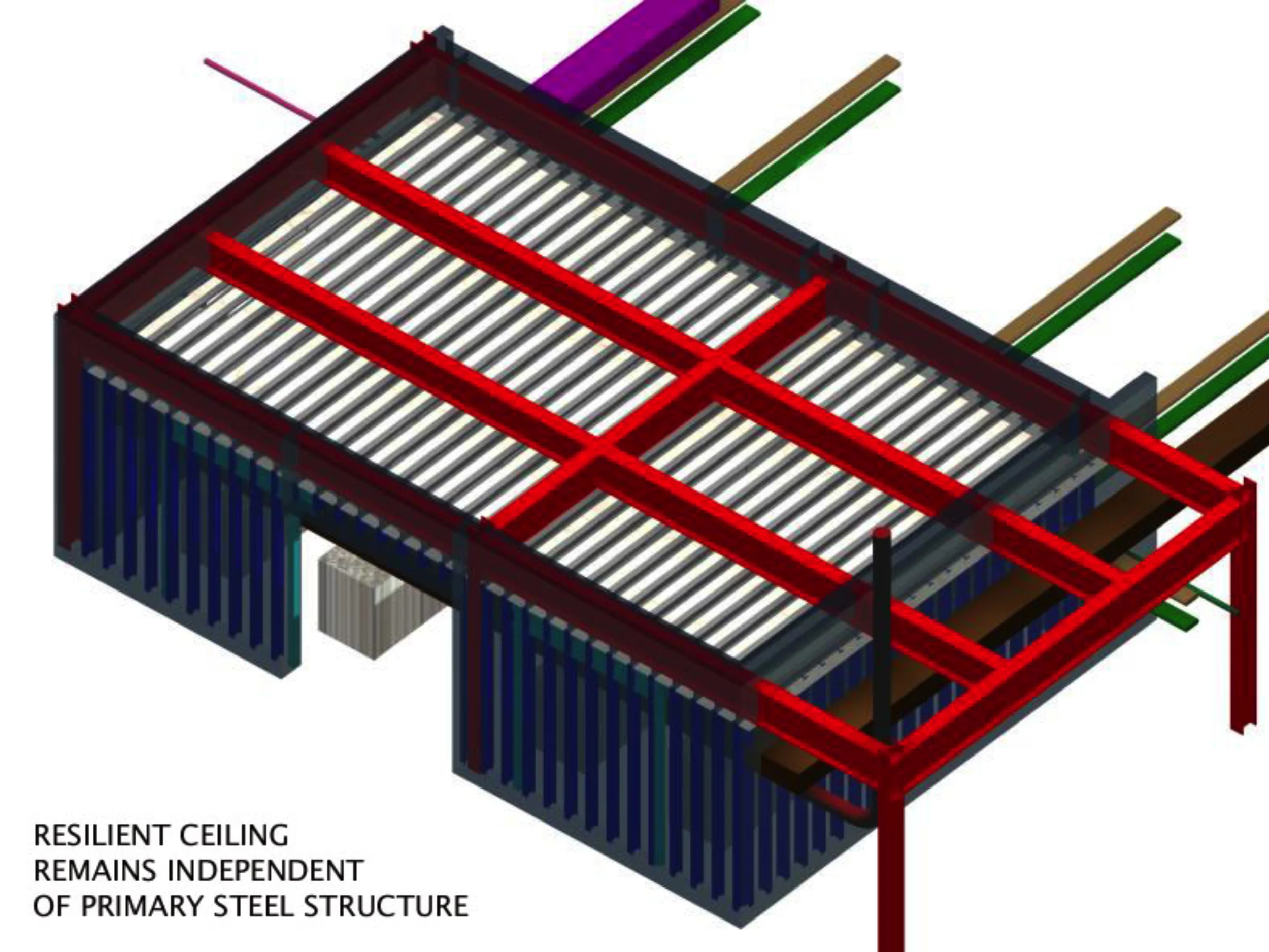
Figure 28: Engine Lab Coordination Model (Resilient Enclosure)

Figure 29: Enlarged Plan from A4.01- Sprinkler Layout
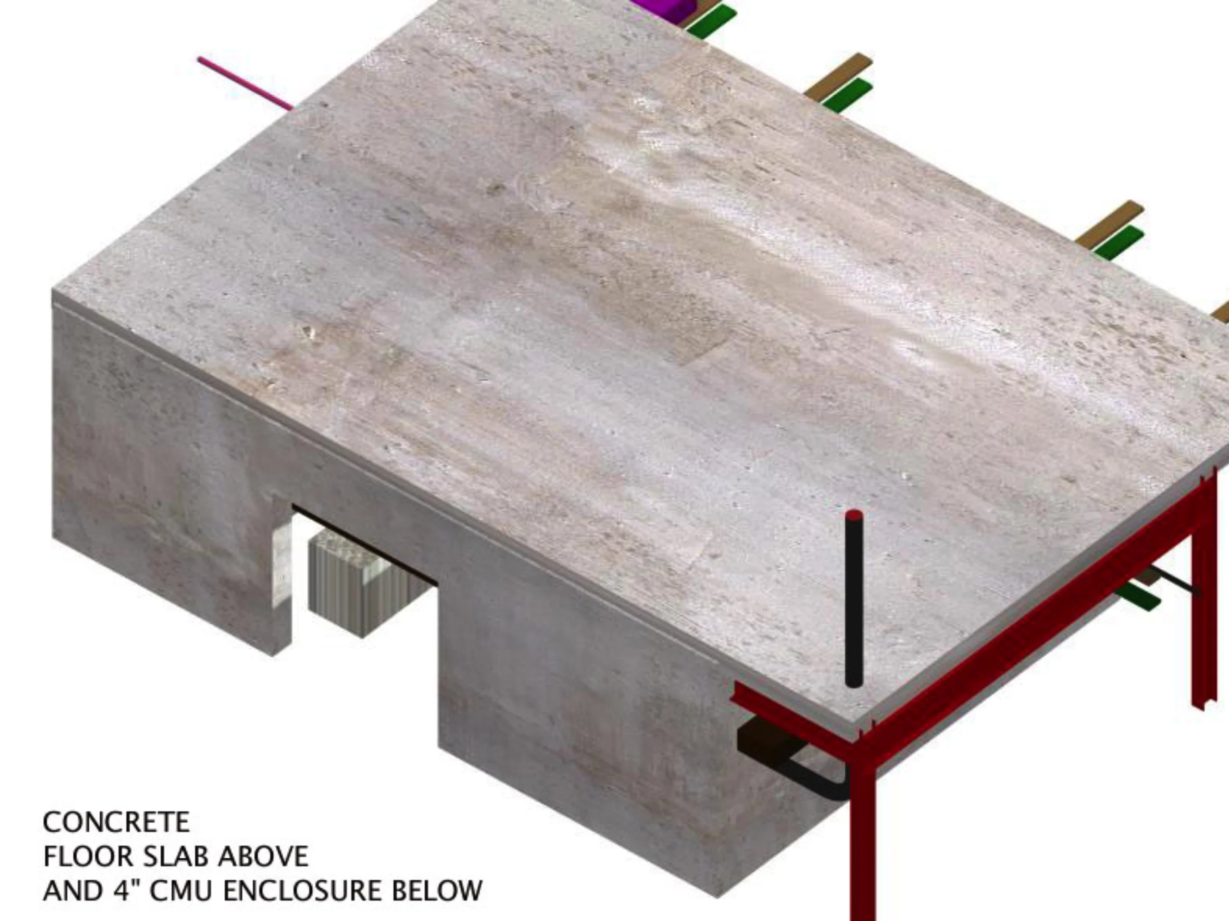
Figure 30: Engine Lab Coordination Model (Resilient Enclosure)
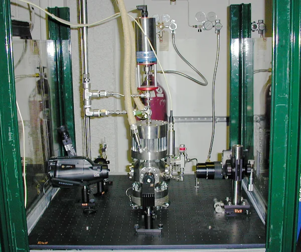
Photo 2: Completed High Pressure Burner in place

Figure 31: Enlarged Plan of High Pressure Combuster
A high-pressure burner is used to study combustion and develop diagnostics under conditions similiar to those in gas turbine engines. A laboratory-scale pulse detonation engine (PDE) is used for the development of laser diagnostics for PDEs. Finally, an expansion tube is used to study supersonic flows.
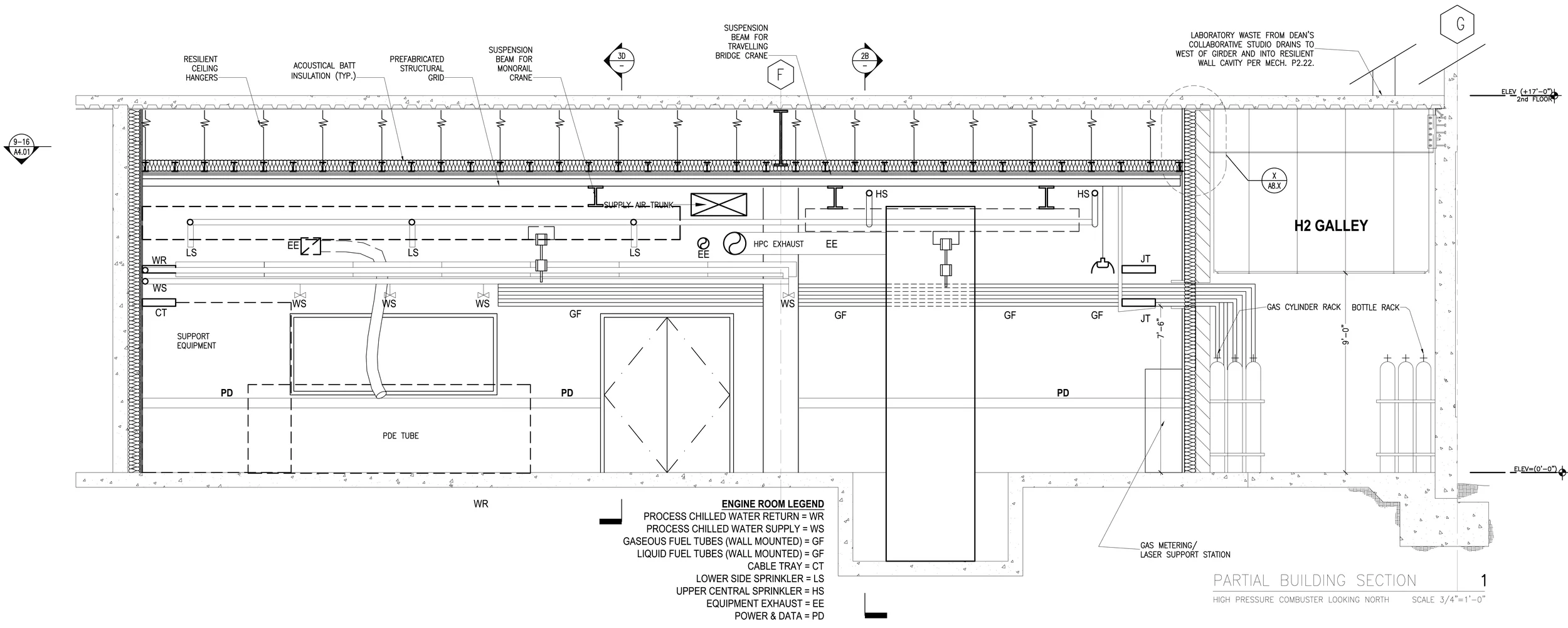
Figure 32: Enlarged Section from Sheet A3.11 of High Pressure Combuster
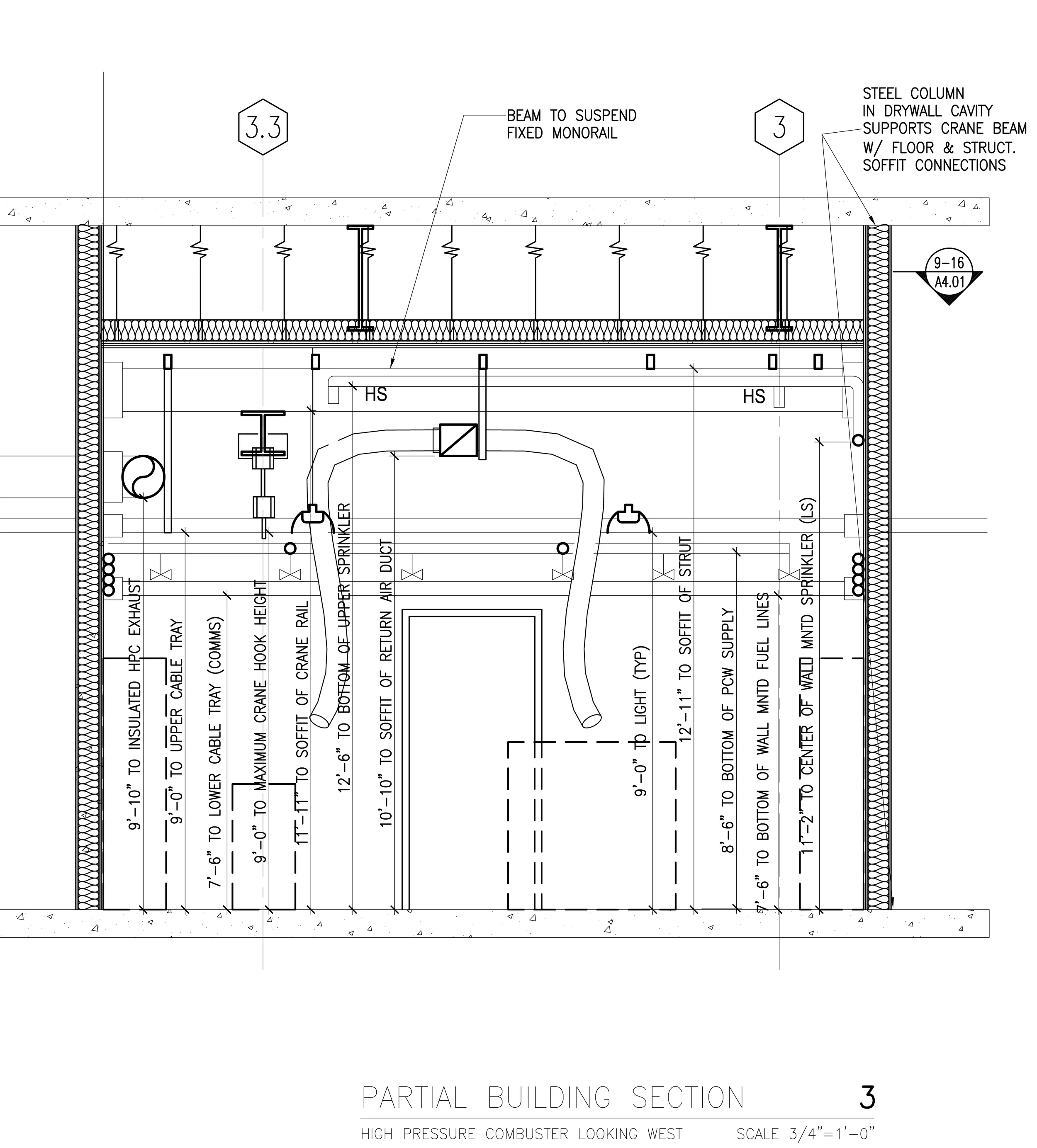
Figure 33: Enlarged Section from Sheet A3.11 of High Pressure Combuster
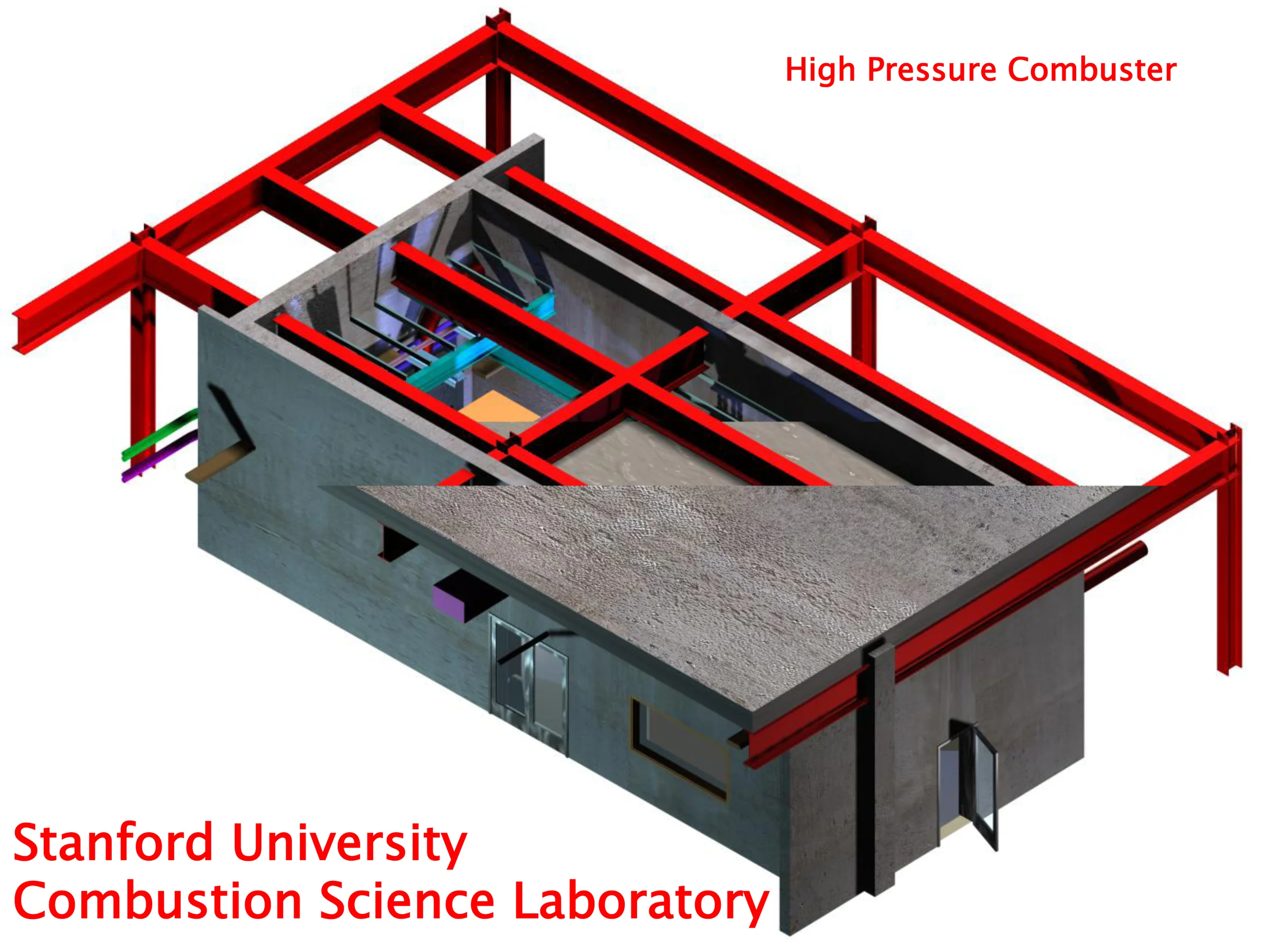
Figure 34: High Pressure Combuster Coordination Model- by John Millard

Figure 35: Enlarged Plan from A4.01- Sprinkler Layout
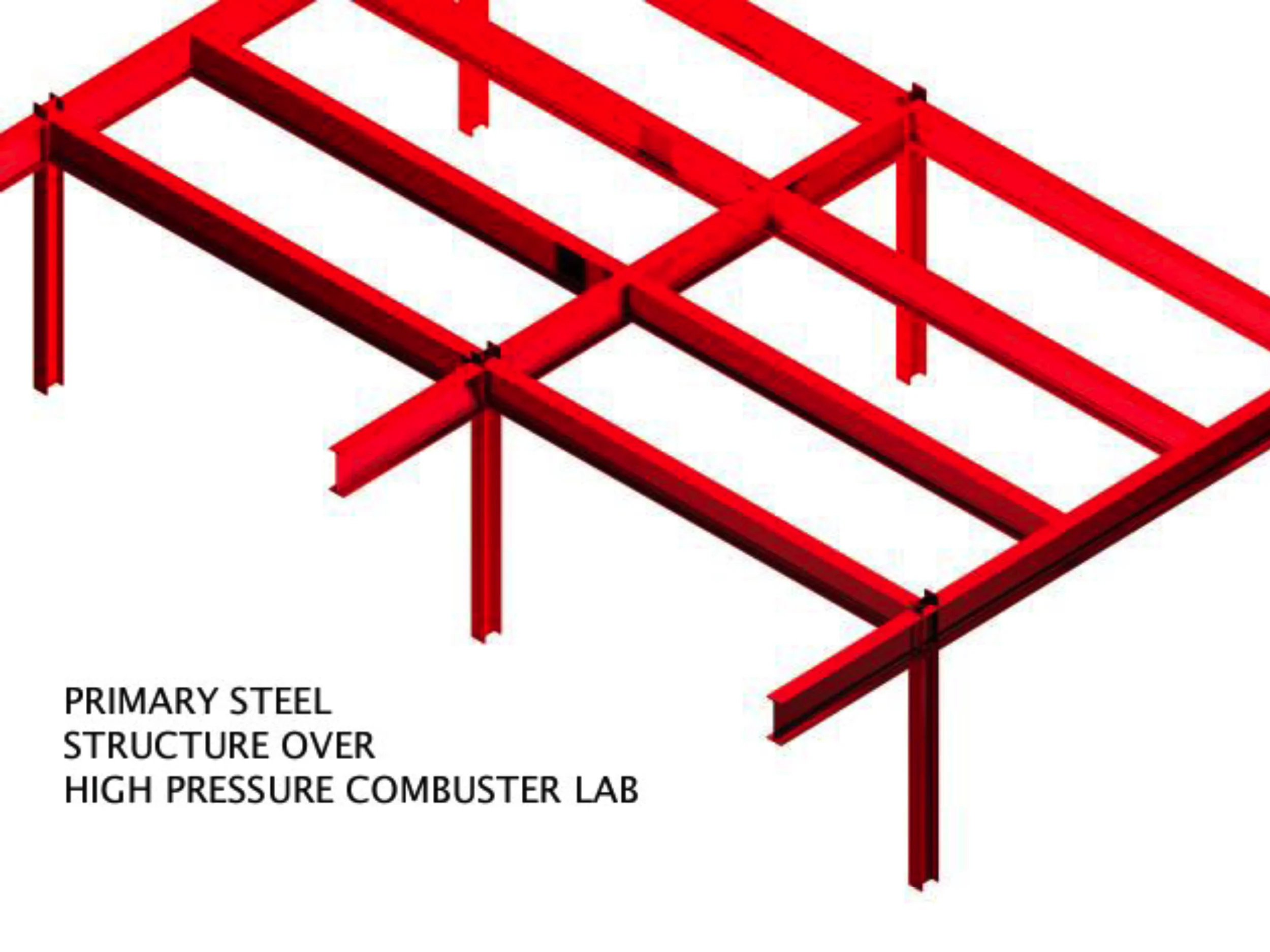
Figure 36: High Pressure Combuster Coordination Model- Primary Structure

Figure 37: Enlarged Section from Sheet A3.11 of High Pressure Combuster
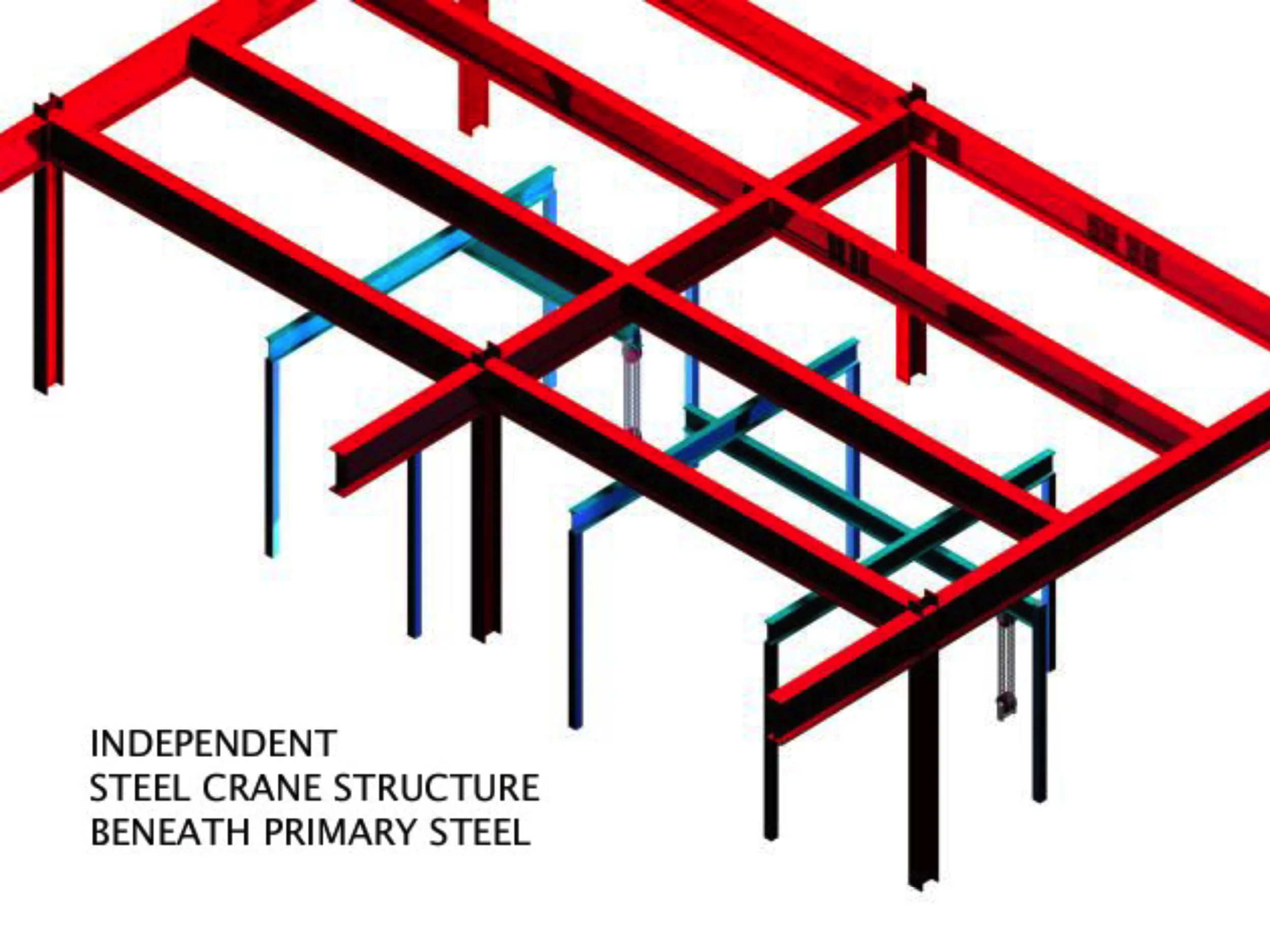
Figure 38: High Pressure Combuster Coordination Model- Primary Structure w/ Traveling Bridge Beam Crane
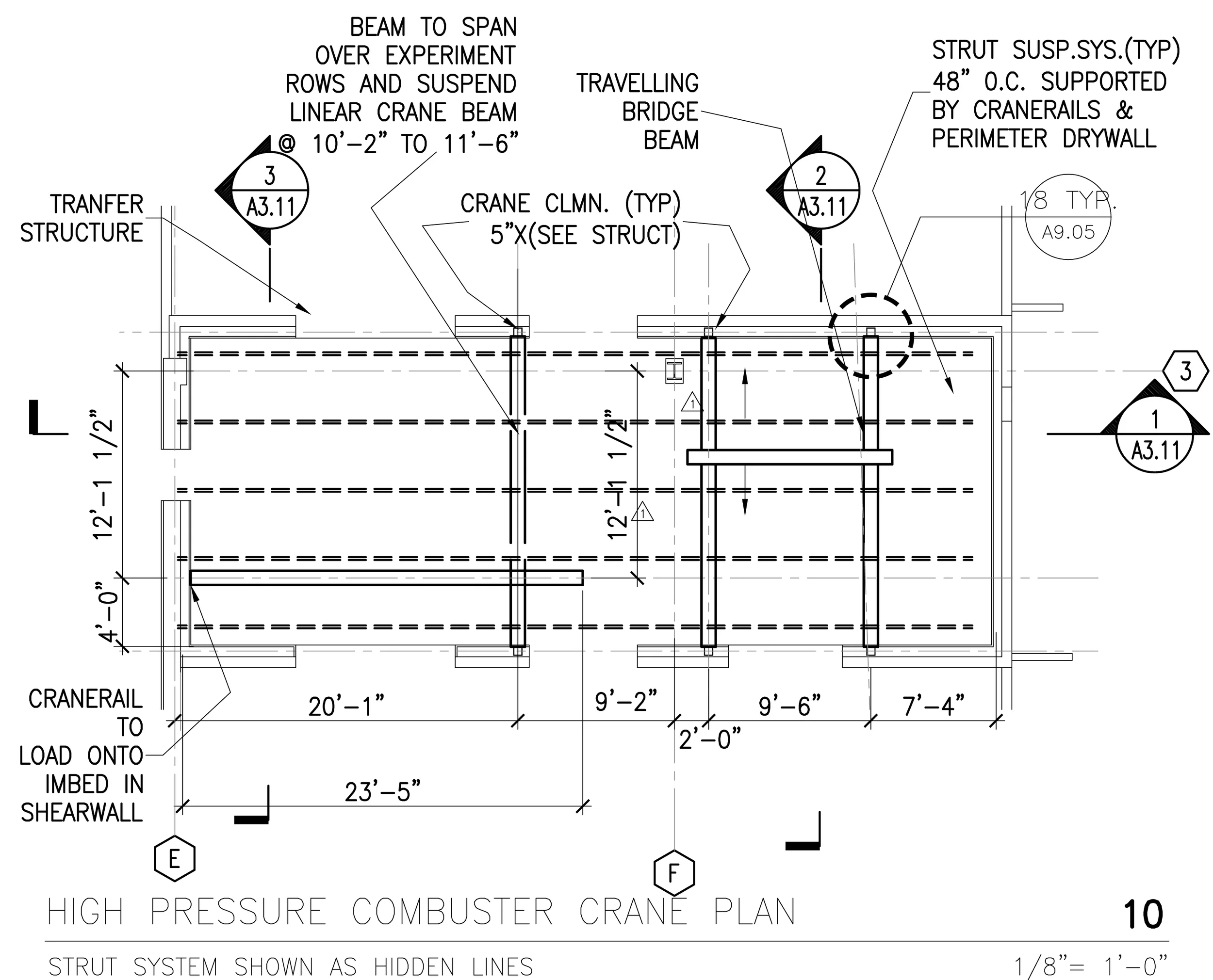
Figure 39: Enlarged Plan from A4.01- Crane Layout
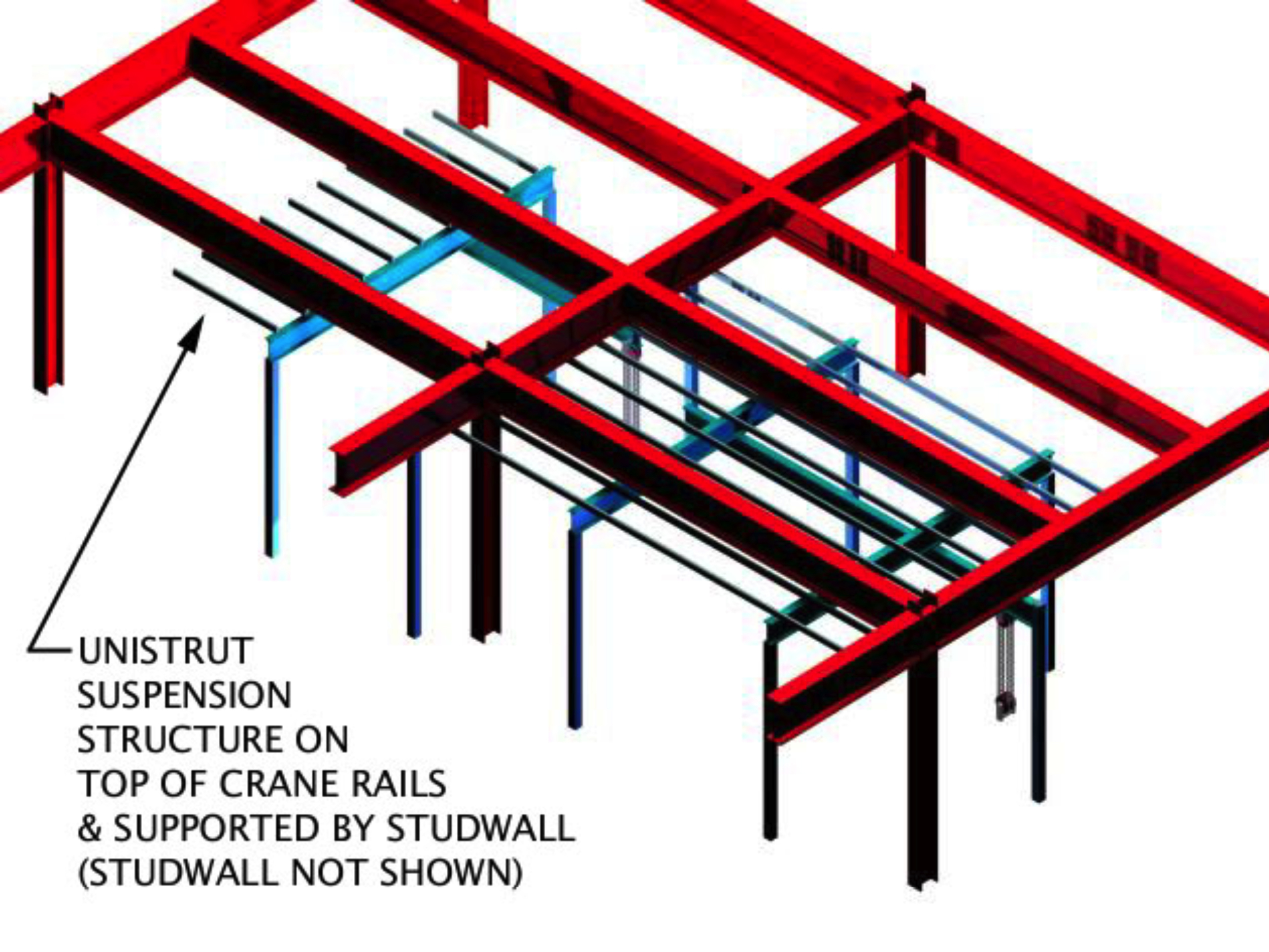
Figure 40: High Pressure Combuster Coordination Model- Crane Layout with Strut Canopy

Figure 41: Enlarged Plan from A4.01- Duct Layout
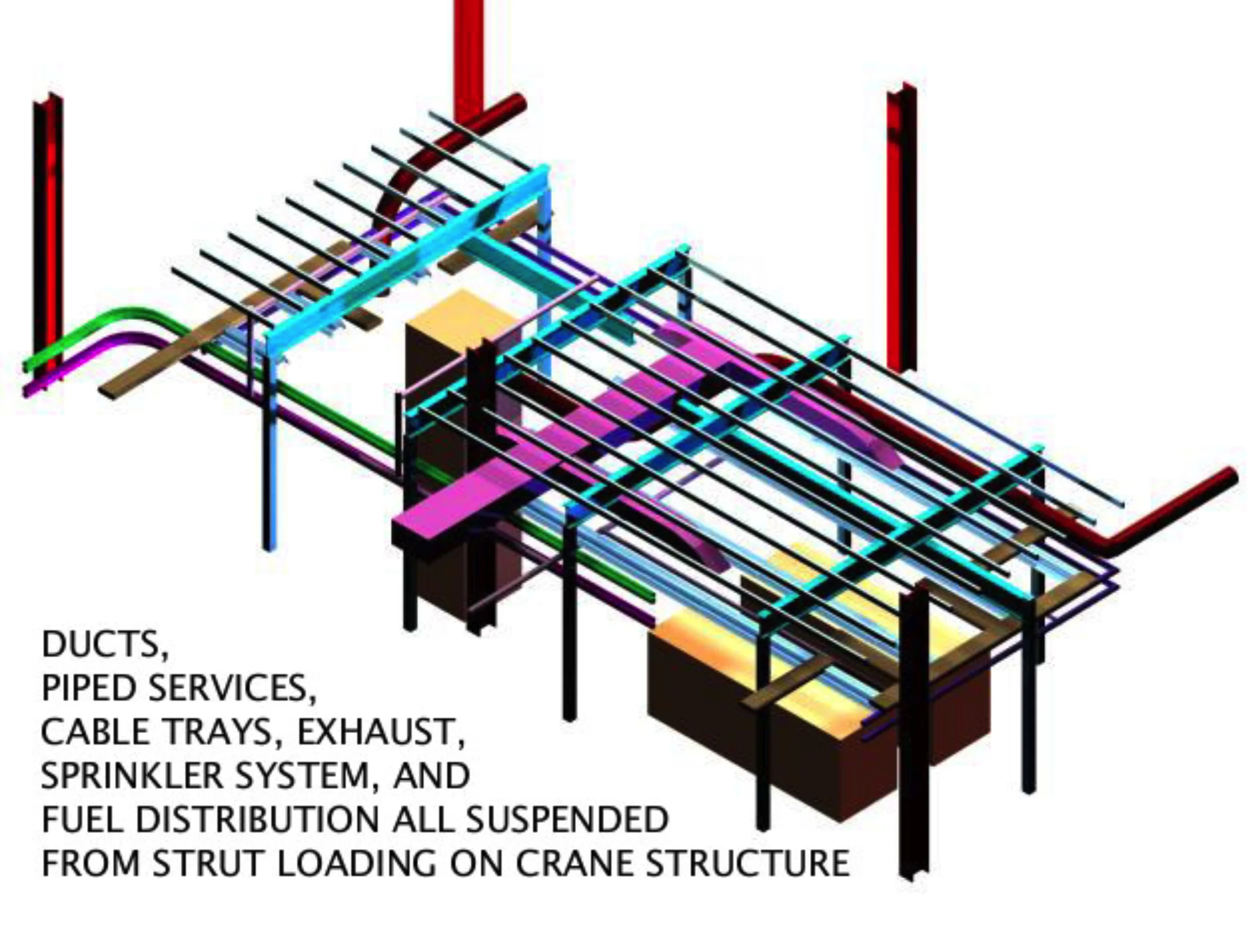
Figure 42: High Pressure Combuster Coordination Model- Ducts, Piped Services, Cable Trays, Exhaust, Sprinkler System, Fuel Distribution, Strut & Crane
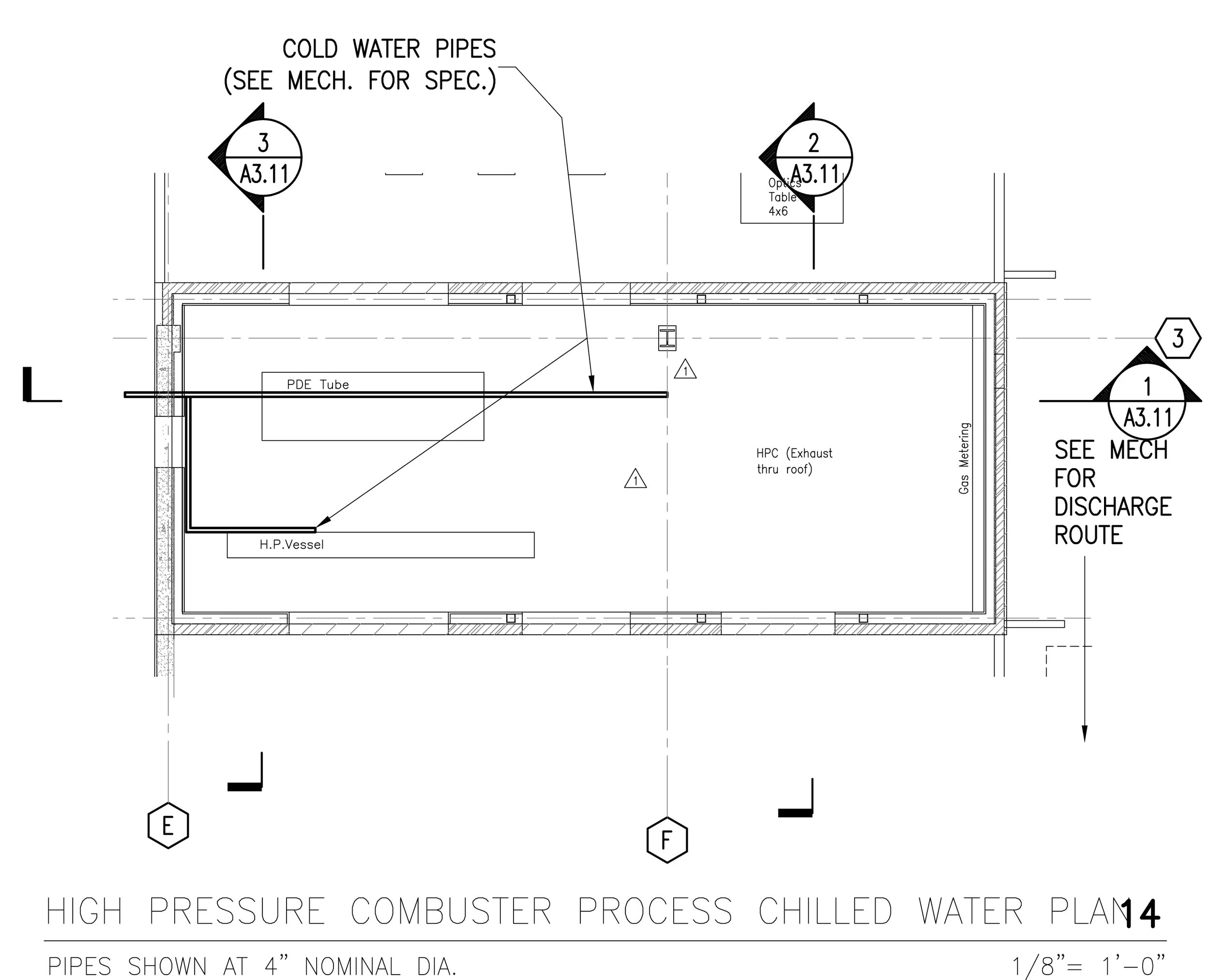
Figure 43: Enlarged Plan from A4.01- Process Chilled Water Layout

Figure 44: High Pressure Combuster Coordination Model- Resilient Enclosure
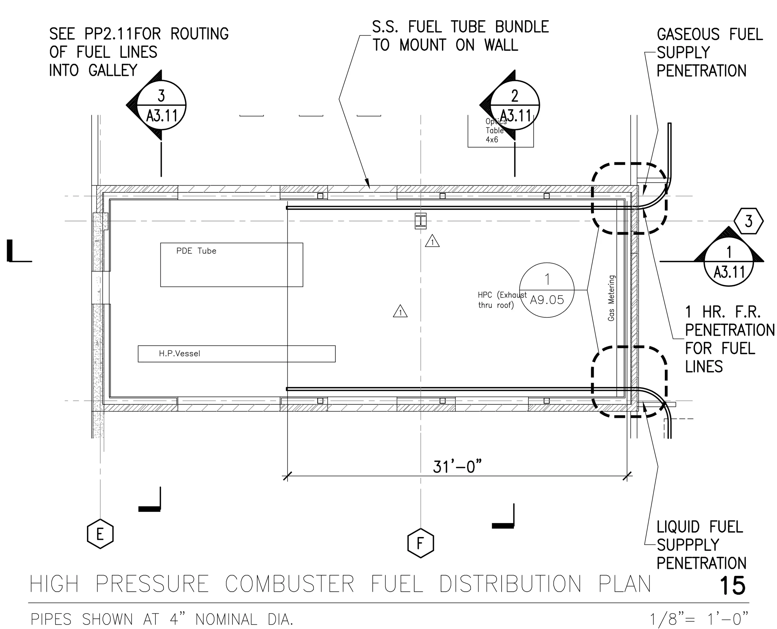
Figure 45: Enlarged Plan from A4.01- Fuel Line Layout
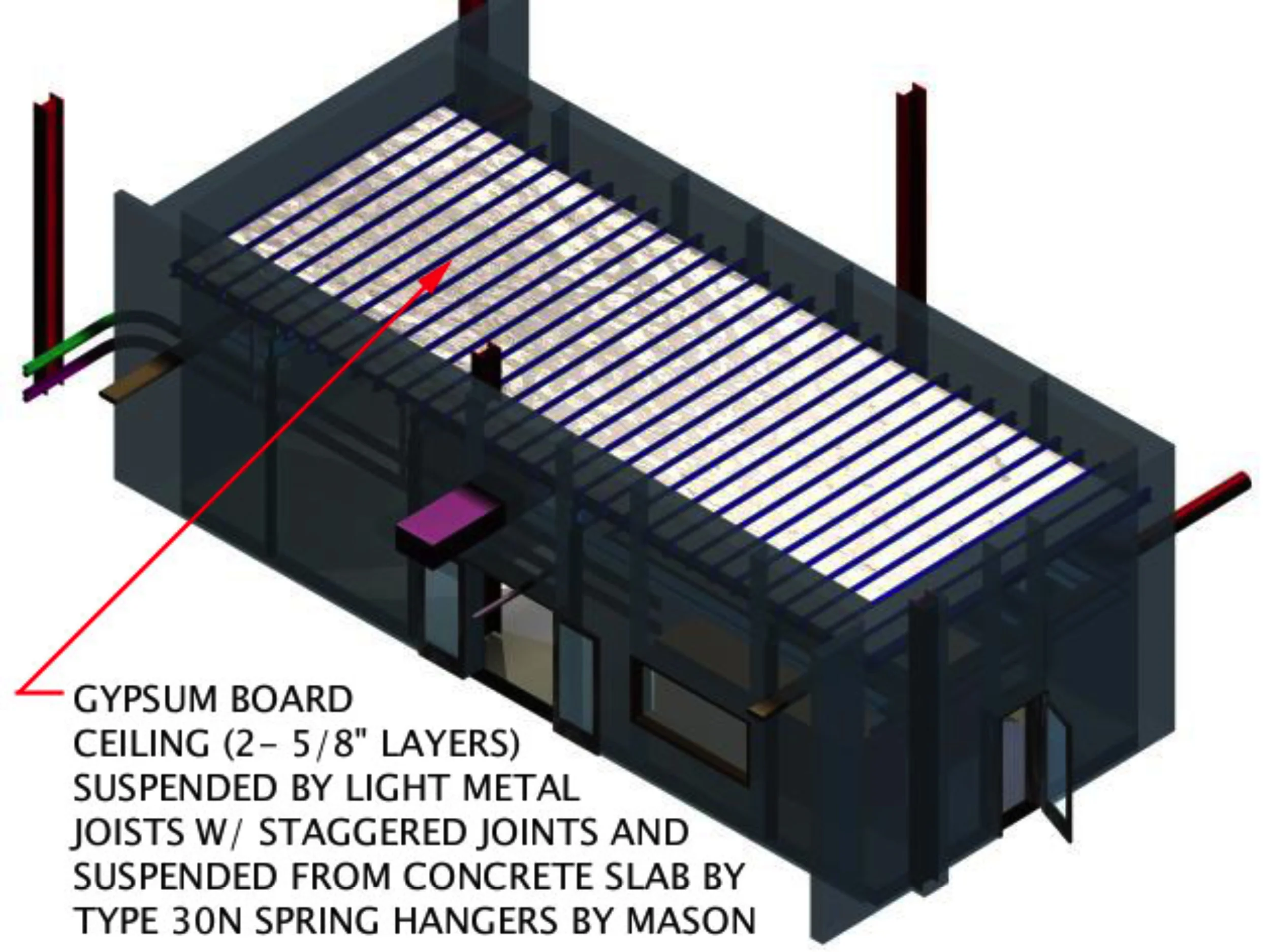
Figure 46: High Pressure Combuster Coordination Model- Resilient Ceiling
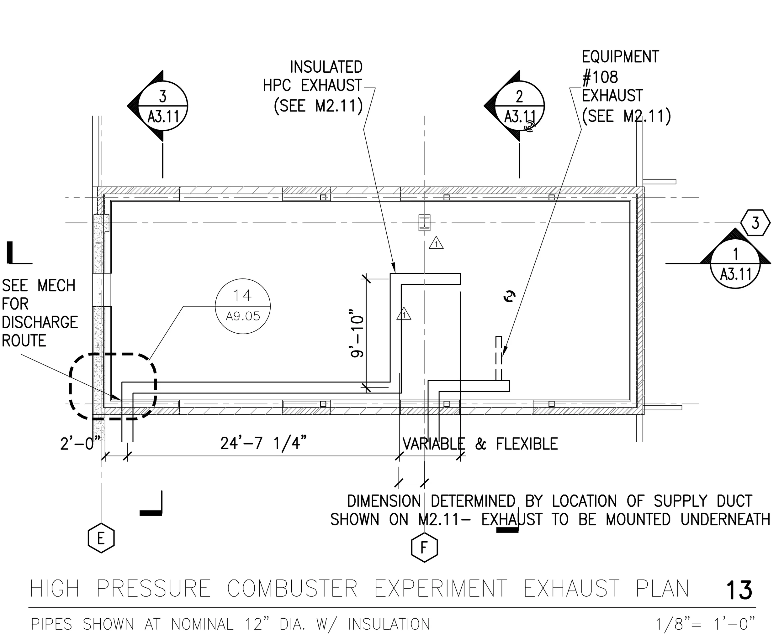
Figure 47: Enlarged Plan from A4.01- Exhaust Layout
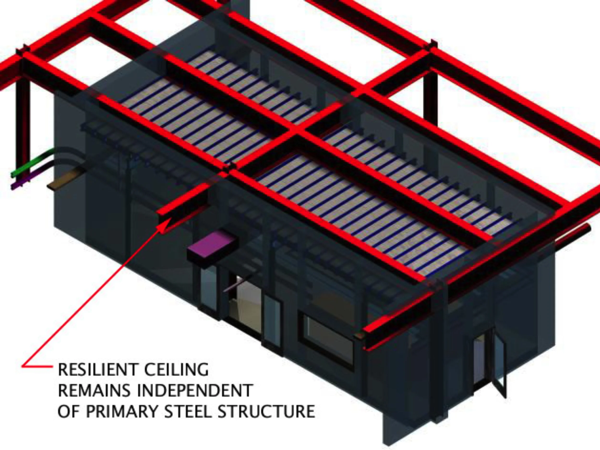
Figure 48: High Pressure Combuster Coordination Model- Resilient Ceiling
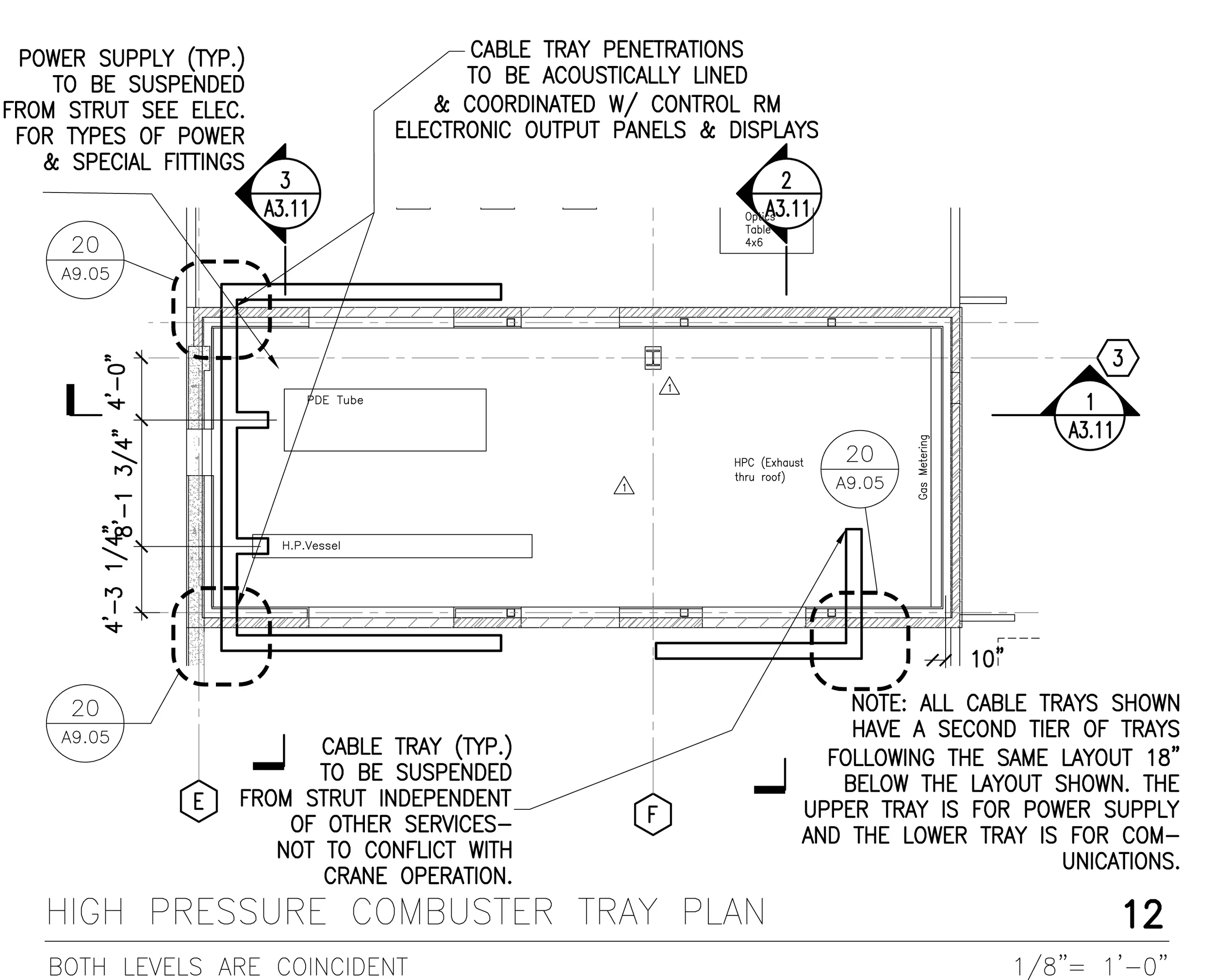
Figure 49: Enlarged Plan from A4.01- Overhead Power & Communications Layout
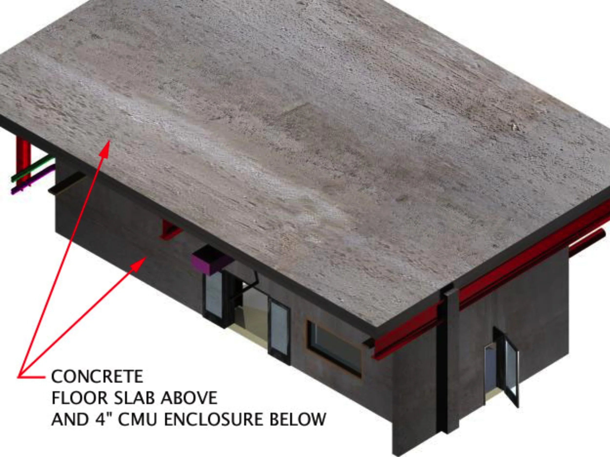
Figure 50: High Pressure Combuster Coordination Model- Fully Enclosed

Figure 51: Enlarged Plan from A4.01- Sprinkler Layout
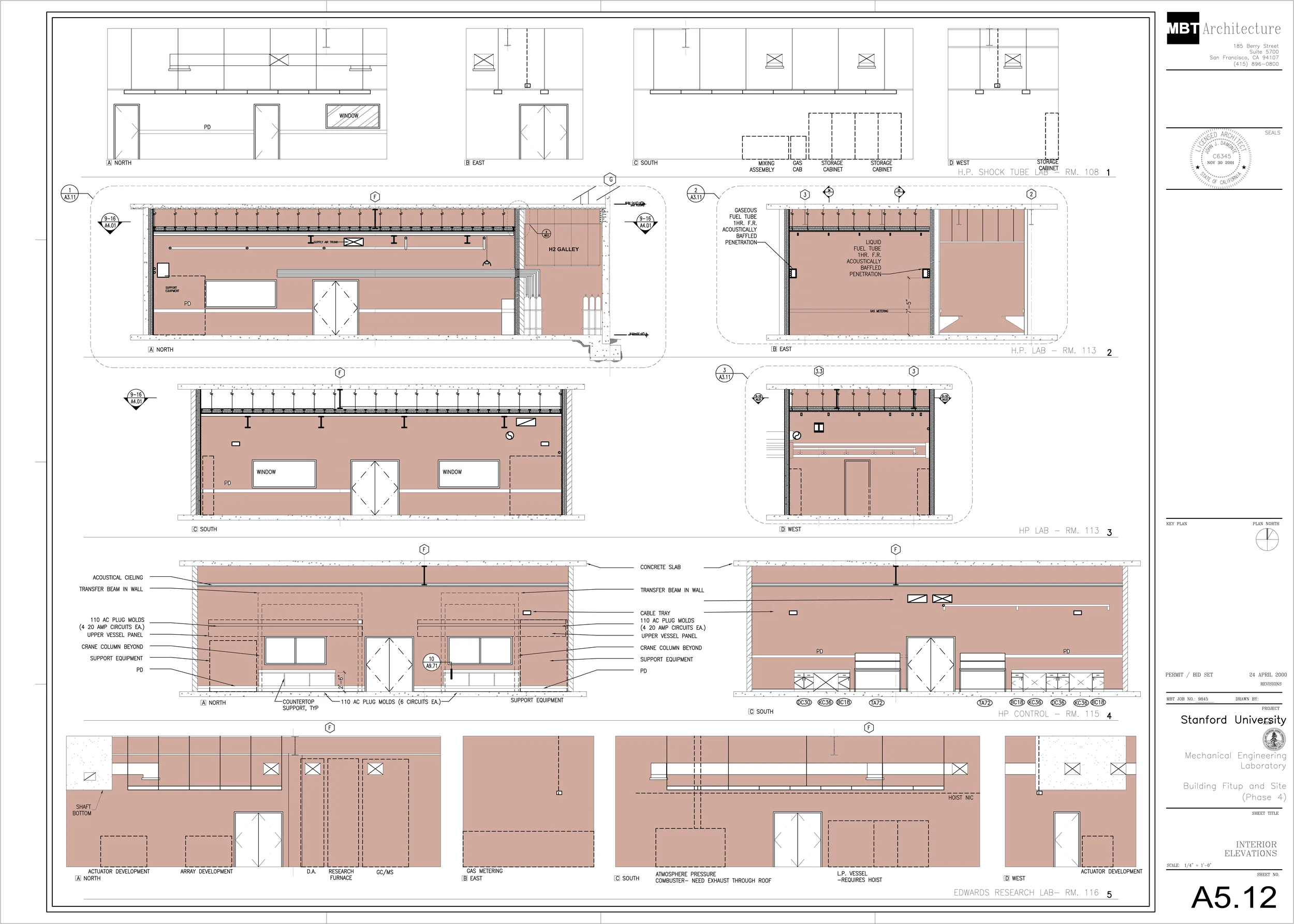
Figure 52: Sheet 5.12 (Shaded area by John Millard)
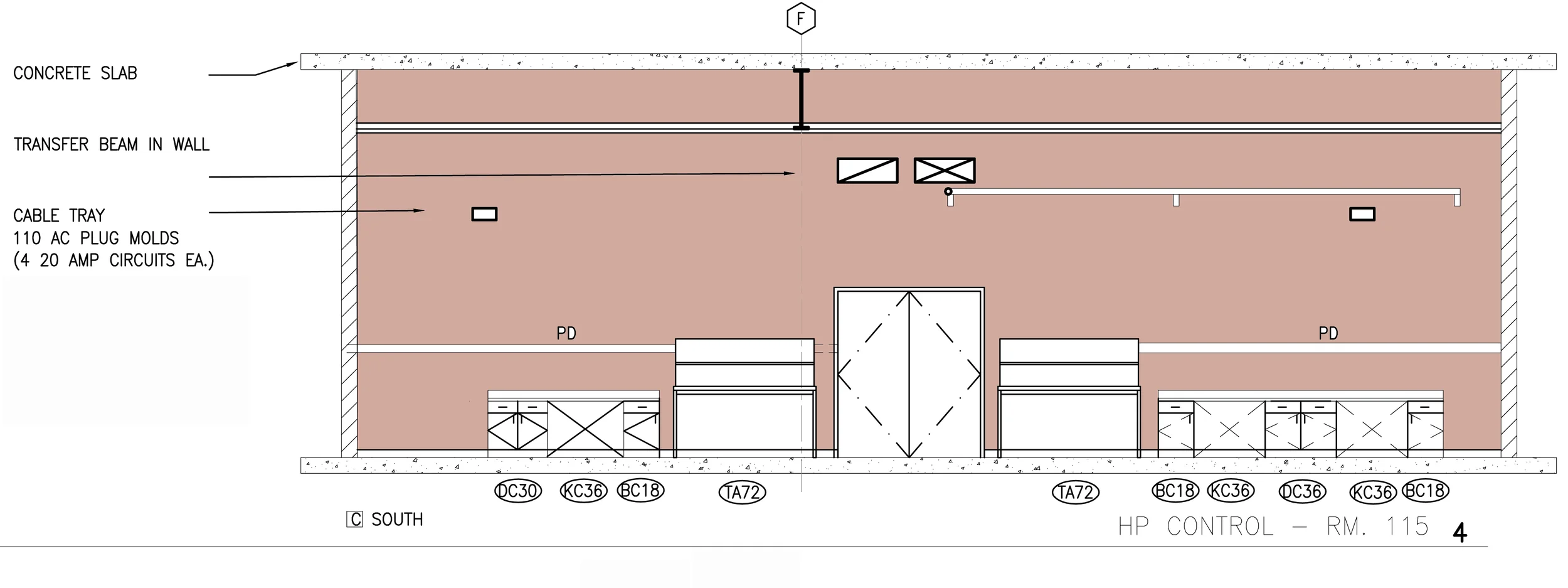
Figure 53: Interior Elevation from Sheet 5.12 Showing HPC Control Room
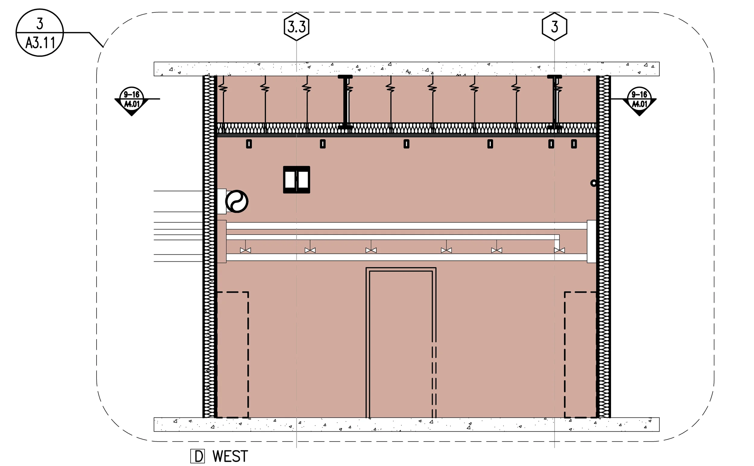
Figure 54: Interior Elevation from Sheet 5.12 Showing HPC Control Room
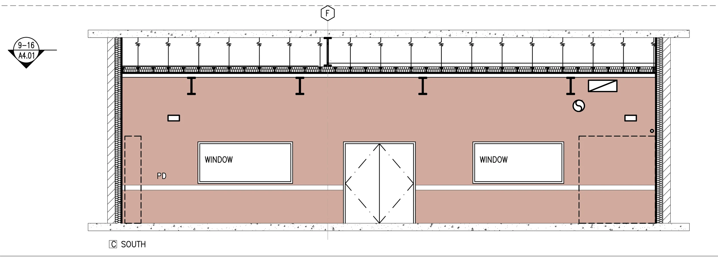
Figure 55: Interior Elevation from Sheet 5.12 Showing HPC Control Room
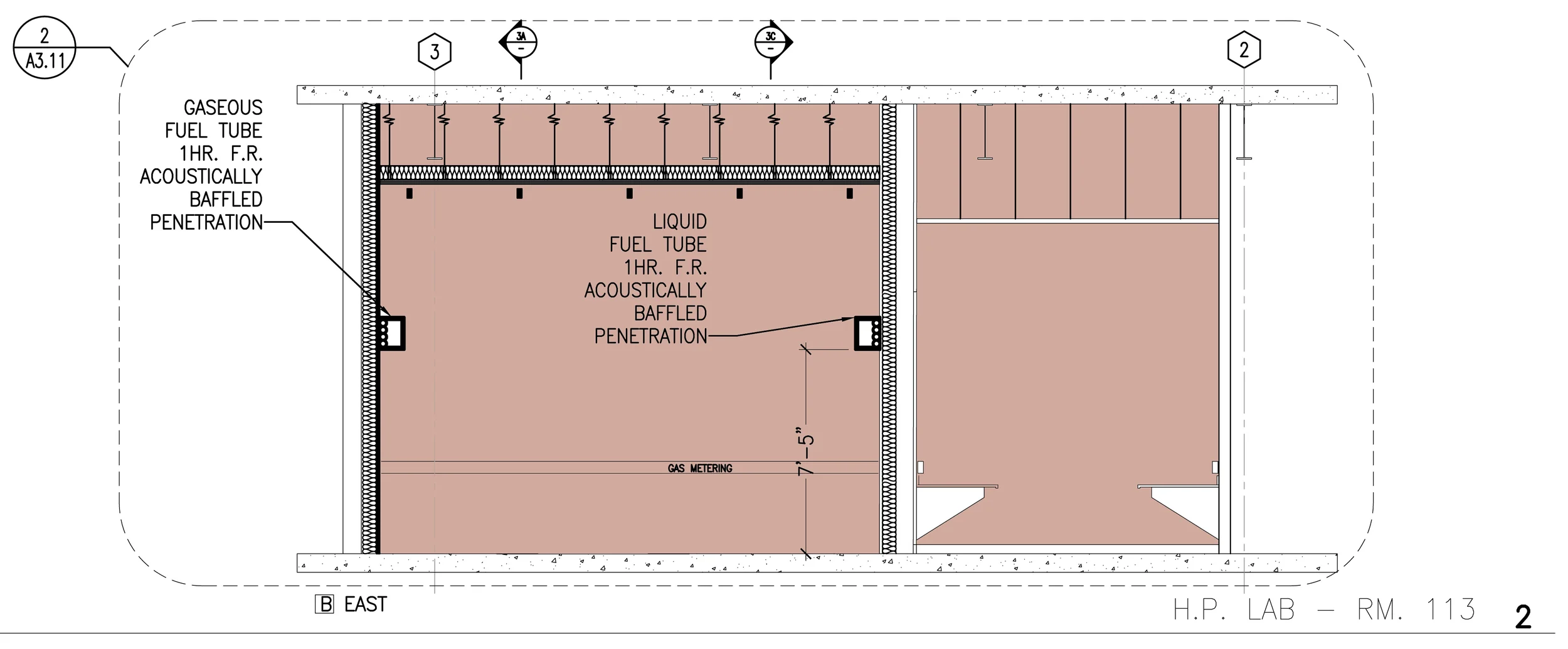
Figure 56: Interior Elevation from Sheet 5.12 Showing HPC Room

Figure 57: Interior Elevation from Sheet 5.12 Showing HPC Room

Figure 58: Interior Elevation from Sheet 5.12 Showing HPC Control Room
