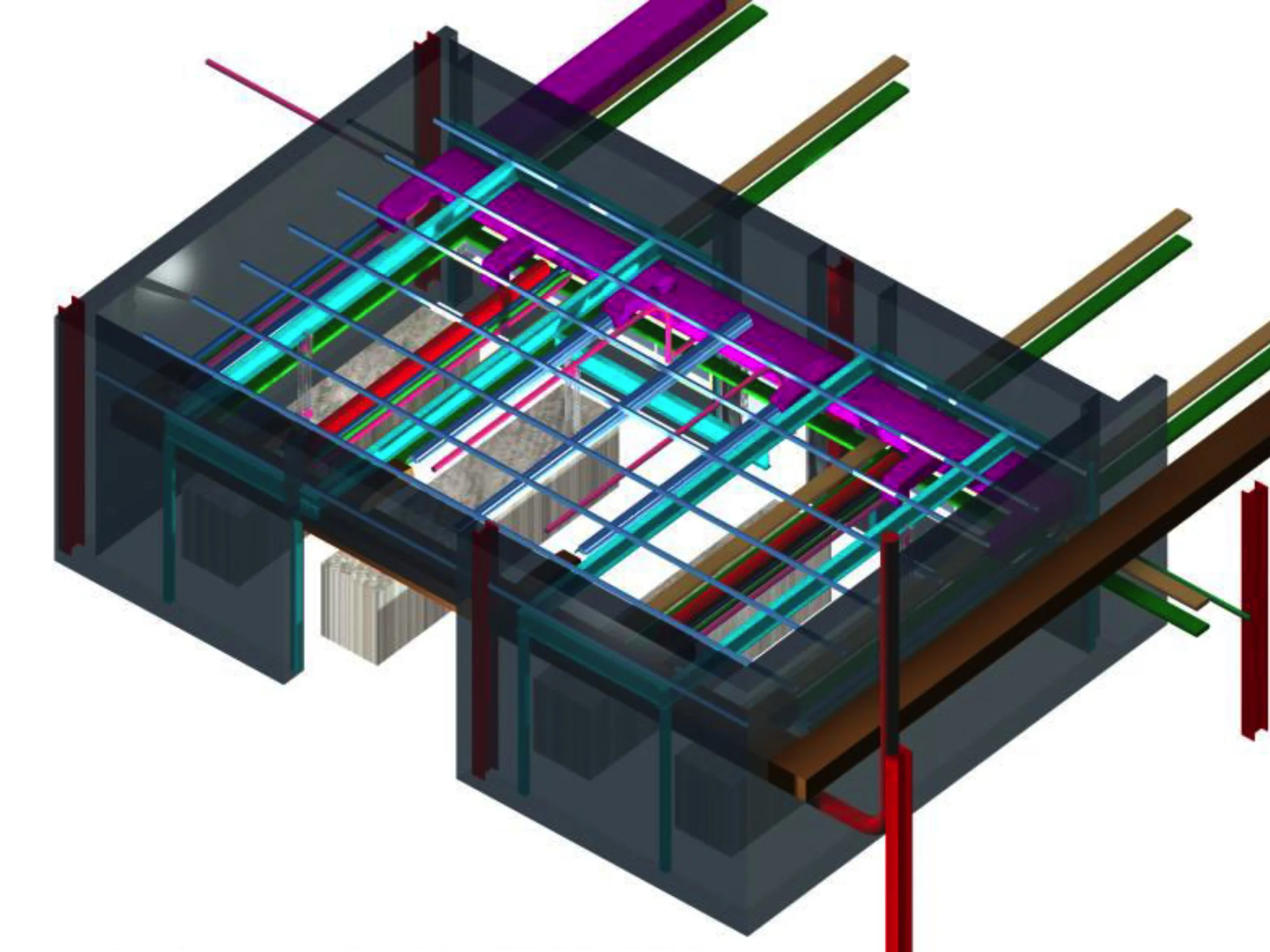
Stanford University, College of Mechanical Engineering- Schematic Design
Project Summary:
Architecture Firm: MBT Architecture, Seattle
Client: Stanford University, College of Mechanical Engineering
Date of Construction Completion: 2002
John Millard's Role: Project Architect for Combustion Science Laboratories (High Pressure Combuster Lab & Engine Laboratory)
Duration of Design Effort: Schematic Design- July/ November 1999, Design Development- Nov.'99/ May 2000, Construction Documentation- May/ October 2000
John Milard joined MBT architecture in September 1998. After working on several laboratory buildings in MBT's Seattle Office, John was asked to join a team of architects in the San Francisco office of MBT to design a new Mechanical Engineering Laboratory for Stanford University's College of Mechanical Engineering. John's scope of work was to design the laboratories for the combustion science part of the building. The schematic phase of design had begun in June 1999. John worked closely with the primary investigators of the combustion science department and designed two laboratories: one for the high-pressure combustor and another for the engine laboratory. Each of these laboratories were highly complex in their requirements due largely to the excessive vibration that was created in each one of the spaces.
The engine laboratory was designed for testing and experimentation of many different kinds of combustion engines. While fuel cells are not strictly combustion engines, fuel cells were tested in the engine laboratory and used hydrogen fuel which is a combustible gas. Other fuels which needed to be stored on site were leadfree gasoline, diesel fuel, jet fuel, oil, and many other gases that required storage and delivery systems to various experiments in the engine lab.
In order to keep the noise from the experiments in the engine lab to a minimum, an acoustical engineer was retained by the team to design a resilient envelope that would eliminate vibration from transferring into the structure of the building. Additionally, in order to manipulate engine blocks and other heavy objects in the engine laboratory a traveling bridge beam crane was required to be suspended from the ceiling of the engine laboratory. In order for this crane to be functional, all of the other overhead services in the engine laboratory had to accommodate the movement of the cream across the floor space. Therefore, all of the exhaust ducts fuel lines, sprinkler pipes, lighting, power and communications cable trays, dedicated engine exhaust and other overhead service components had to be carefully planned around the movement of the crane.
The engine laboratory also had a complex series of slab depressions that accommodated everything from excess sprinkler water to a large dynamometer used to absorb the energy from experimental car acceleration. This dynamometer required base isolation in order to protect the slab from experiencing vibration from the dynamometer.
In order to store the vast amount of fuel required to conduct combustion science experiments in the engine lab, a hazardous substances galley was required to be constructed next to the engine lab that would have a separate hazardous substances occupancy rating and would be designed to have explosion panels to defray the force of an explosion that might occur in this separate occupancy.
The primary steel structure of the building was to be defended against these vibrations that emanated from the experiments in the engine laboratory at all possible costs. The acoustical engineer for the project designed a resilient envelope that was comprised mainly of multiple layers of gypsum wall board. This primary defense against noise being transmitted into the teens collaborative laboratories just one floor above the entry lab required additional structure to support the resilient envelope. An array of light gauge metal joists were hung from the concrete slab by springs.
These fittings known as spring hangers suspended two layers of 5/8" gypsum wallboard above the crane rails of the crane structure in order to isolate the GWN from crane rail vibration.
And array of strut was required across the entire ceiling surface to suspend components for experiments as well as lighting and other overhead services. In order to present the transference of vibration from these components into the struts and consequently into other parts of the building structure –special detailing of these assemblies was necessary in order to keep noise out of the rest of the building. John Millard was responsible for detailing these conditions that might otherwise have resulted in a conventional detail that transmitted vibration. John worked closely with the acoustical engineer who had review and approval rights to all of the work that was produced. These details are shown in the construction documents section of this portfolio.
The schematic design phase of the mechanical engineering building project was carried out between June 1999 and September 1999. During this time the specifications, user requirements, equipment specifications, service requirements and other engineering related disciplines were all conferenced with the owner during this time. The three-dimensional coordination models shown to the clients were presented to the owner in a review and approval process with the facility management at Stanford University College of Mechanical Engineering.
Schematic Design Issue: Engine Laboratory Occupancy Classification
Summary: This is to confirm the occupancy classification of the Engine Laboratory portion of the above, mixed-occupancy project. The Architect has reviewed the issue of an S-3 versus H-4 occupancy classification at meetings with the above agency representatives on January 28th and May 5th, 1999 (Tom Whisler not present at the second meeting). Since the building code interpretation on this matter is not an obvious one and the occupancy classification significantly impacts the design and construction requirements, it is important that the classification be firmly established prior to entering the design development phase of the project.
Background: The area in question contains 2,070 square feet of space on the first floor of the building. It is divided into the Engine Room and Engine Control Room. The function of these rooms is best summed up by information provided by the future users: "The engine lab is used both for operational engine tests and for dissection and modification of engines. Engine testing involves operation of an engine attached to a loading device (dynamometer) over a range of speeds and loads. Performance data are collected and analyzed. Exhaust emissions are sampled and analyzed. Alternative engine systems (ignition, control programming, fuel injection, etc) are studied. Engines are dissected as part of reverse-engineering studies. Engines are also modified as needed for the engine experiments. Note that many normal auto-shop activities do not take place in the engine lab: tank cleaning, welding, painting,… The activities in the lab more closely resemble those of a combustion research laboratory than they do an auto repair facility." It should be noted that in addition to the absence of welding, no open flames are used in this space. Personnel are primarily stationed in the Control Room during operation of the engines, although they occasionally enter the Engine Room to make an adjustment. Most importantly, materials (fuels, engine lubricants, et cetera) storage is in the H-2 space, next door. Combustible fuels are piped directly to the engines in closed systems.
Conclusion: S-3 Occupancy Definition: “…include repair garages where work is limited to the exchange of parts and maintenance requiring no open flame or welding…” H-4 Occupancy Definition: “Repair garages not classified as H-4.” The project code analysis currently assumes the worst-case scenario in terms of occupancy-based restrictions, which is that of an H-4 classification. However, if the factor separating S-3 and H-4 is that of materials storage and use, then the programmed activities appear to occur within the limitations of the S-3 classification. Despite the user’s opinion as to what the lab activities most closely resemble, the material uses are more in alignment with that of a B-occupancy type of laboratory facility. As such, we proposed the Engine Laboratory facility be designated an S-3 occupancy.
Schematic Design Issue: Mechanical Vibration Control and Isolation Specification:
PART 1 - - GENERAL
1.1 WORK INCLUDED
A. This Section specifies the requirements for vibration control systems to be used in all phases of architectural, mechanical, electrical, and structural work.
B. This Specification provides the necessary design for the avoidance of excessive vibration and structural borne noise in the building due to the operation of machinery or equipment and/or due to interconnected piping, ductwork, conduit, or structures.
Due to the high technology nature of this facility the design criteria any exceed those of normal industrial construction. It is imperative that close attention be paid to all specifications and details for noise and vibration control.
1.4 DESIGN CRITERIA: A. Equipment, ductwork, piping and conduit shall not be installed which makes rigid contact with the structure unless it is allowed by this specification. B. Pipe Anchors and Supports: Piping supports and anchors shall not interfere with free operation of vibration isolation systems. Stiff-leg support of piping supported on Type HS, or Type FSN isolators is not acceptable. C. Ductwork: Ductwork isolation requirements are based on duct equivalent diameters. For rectangular ductwork, the equivalent diameter is the diameter of duct having the same cross-sectional area. D. Equipment Isolation Frames and Bases: Frames and bases used to support vibration isolated pumps shall be sized to provide support for pipe elbows. E. Isolation/Absorption Products: The completed installation must be free of unacceptable vibration and noise. Systems, equipment, or parts which vibrate or generate vibration unduly, or which generate or emit undue noise while in operation, shall: (1) be adjusted, repaired, or replaced as appropriate to obtain acceptable levels of vibration or noise, or (2) be supported on, or fitted with, suppression or absorption devices, or other means, which effectively prevent the transmission of vibration or noise beyond the offending item. F. Resilient Wall, Ceiling, and Floor Penetrations: Provide resilient wall and ceiling penetrations for all piping, conduit, ductwork, etc. supported on Type HS or Type FSN isolators. Refer to resilient penetration details on the Drawings.
2.2 VIBRATION ISOLATORS
A. General:
1. Metal parts of vibration-isolation units shall be as follows: Galvanizing shall meet ASTM Salt Spray test Standards and Federal Test Standard no. 14.
a. Housing: Hot-dipped galvanized or fusion epoxy coated.
b. Hardware (washers, nuts, bolts, etc.): Cadmium plated.
c. Springs shall be neoprene coated.
2. All isolators installed outdoors shall have base plates with bolt holes for fastening the isolators to the support members.
3. Isolator types are scheduled to establish minimum standards. At the Subcontractor's option, labor-saving accessories can be an integral part of isolators supplied to provide initial lift of equipment to operating height, hold piping at fixed elevation during installation and initial system filling operations, and similar installation advantages. Accessories shall not degrade the vibration isolation system.
4. Static deflection of isolators shall be as indicated in Table 15240, Vibration Isolation Schedule. All static deflections stated are the minimum acceptable deflection for the mounts under actual load.
5. The use of nested springs or of multiple parallel springs within a single mount is not permitted.
B. Unit FSN (Floor Spring and Neoprene):
1. Spring isolators shall be free-standing and laterally stable without any housing. Spring diameter shall be not less than 0.8 times the compressed height of the spring at the design load. Springs shall have a minimum additional travel to solid equal to 50 percent of the actual deflection. Springs shall be so designed that the ratio of horizontal stiffness to vertical stiffness is approximately 1. All mounts shall have leveling bolts.
2. The spring element in the isolator shall either be set in a neoprene cup and have a steel washer to distribute the load evenly over the neoprene, or each isolator shall be mounted on a unit DNP isolator. If the DNP isolator is used, a rectangular bearing plate of appropriate size to load the pad uniformly in the range of 40 to 50 psi shall be provided. If the spring isolator is supplied with a neoprene friction pad, a stainless steel, aluminum, or galvanized steel plate shall be used between the friction pad and the DNP isolator. The DNP isolator, separator plate, and friction pad shall be permanently adhered to one another and to the bottom of the bearing plate.
3. If the isolator is to be fastened to the building structure and a unit DNP isolator is used under the bearing plate, neoprene grommets shall be provided for each bolt hole in the base plate. Bolt holes shall be properly sized to allow for grommets. Hold down bolt assembly shall include washers to distribute load evenly to the grommet. Bolts and washers shall be galvanized.
4. Unit FSN isolators shall be one of the following products, or approved equal, with the appropriate neoprene pad (if used) selected from Unit DNP:
a. Type SLF: M.I.
b. Type FDS: K.N.C.
c. Type AC or AD: V.M.C.
C. Unit FSNTL (Floor Spring and Neoprene Travel Limited):
1. Spring isolators shall be free-standing and laterally stable without any housing. Spring diameter shall be not less than 0.8 times the compressed height of the spring at the design load. Spring shall have a minimum additional travel to solid equal to 50 percent of the actual deflection. Springs shall be so designed that the ratio of horizontal stiffness to vertical stiffness is approximately 1. All mounts shall have leveling bolts. All mounts shall have vertical travel limit stops to control extension when weight is removed. The travel limit stops shall be capable of serving as blocking during erection of the equipment. A minimum clearance of 1/4 inch shall be maintained around restraining bolts and between the limit stops and the spring to avoid interference with the spring action.
2. The spring element in the isolator shall either be set in a neoprene cup and have a steel washer to distribute the load evenly over the neoprene, or each isolator shall be mounted on a unit DNP isolator. If the DNP isolator is used, a rectangular bearing plate of appropriate size to load the pad uniformly in the range of 40 to 50 psi shall be provided. If the spring isolator is supplied with a neoprene friction pad, a stainless steel, aluminum, or galvanized steel plate shall be used between the friction pad and the DNP isolator. The DNP isolator, separator plate, and friction pad shall be permanently adhered to one another and to the bottom of the bearing plate.
3. If the isolator is to be fastened to the building structure and a unit DNP isolator is used under the bearing plate, neoprene grommets shall be provided for each bolt hole in the base plate. Bolt holes shall be properly sized to allow for grommets. Hold down bolt assembly shall include washers to distribute load evenly to the grommet. Bolts and washers shall be galvanized.
4. Unit FSNTL isolators shall be one of the following products, or approved equal, with the appropriate neoprene pad (if used) selected from Unit DNP
a. Type SLR: M.I.
b. Type FLS: K.N.C.
c. Type AWR-1: V.M.C.
D. Unit FN (Floor Neoprene):
1. Neoprene isolators shall be neoprene-in-shear type with steel reinforced top and base. All metal surfaces shall be covered with neoprene. The top and bottom surfaces shall be ribbed. Bolt holes shall be provided in the base and the top shall have a threaded fastener.
2. The mounts shall include leveling bolts that may be rigidly connected to the equipment.
3. Unit FN isolators shall be one of the following products or approved equal:
a. Type ND: M.I.
b. Type RD: K.N.C.
c. Type R/RD: V.M.C.
E. Unit NP (Neoprene Pad)
1. Neoprene pad isolators shall be one layer of 1/4-inch to 5/16-inch thick ribbed or waffled neoprene. Neoprene shall be 40 to 50 durometer. The pads shall be sized so that they will be loaded within the manufacturer's recommended range.
2. Unit NP isolators shall be one of the following products or approved equal:
a. Type W: M.I.
b. Type NPS: K.N.C.
c. Type Shear-Flex or Maxi-Flex: V.M.C.
F. Unit DNP (Double Neoprene Pad):
1. Neoprene pad isolators shall be formed by two layers of 1/4-inch to 5/16-inch thick ribbed or waffled neoprene, separated by a stainless steel or aluminum plate. these layers shall be permanently adhered together. Neoprene shall be 40 to 50 durometer. The pads shall be sized so that they will be loaded within the manufacturer's recommended range.
2. Unit DNP isolators shall be formed from one of the following products or approved equal:
a. Type WSW: M.I.
b. Type NPS: K.N.C.
c. Multiple Layers of Type Shear-Flex or Maxi-Flex: V.M.C.
G. Unit HS (Hanger Spring):
1. Vibration-isolation hangers shall consist of a free-standing laterally stable steel spring set into a neoprene cup, contained within a steel housing. The neoprene cup shall be manufactured with a grommet (or other element) to prevent the hanger rod from contacting the hanger housing. A steel washer shall be provided in the neoprene cup to evenly distribute load onto the neoprene.
2. The plate or washer at the top of the spring shall be welded to the spring. The hanger rod shall be securely fastened to this plate or washer using lock nuts. The hanger rod shall have a diameter not less than 5/8 inch. This design represents a modification to the unit types given below. The modification is intended to limit the side-to-side motion of the hanger rod relative to the hanger casing.
3. Spring diameter and hanger housing lower hole sizes shall be large enough to permit the hanger rod to swing through a 30 degree arc before contacting the housing. Spring elements shall have minimum additional travel to solid equal to 50 percent of the actual deflection.
4. Upper hanger rod attachment shall be made through a neoprene rubber-in-shear element designed to avoid direct contact between the hanger rod and the isolator frame.
5. Springs shall be color coded for ease of identification and removable, for field connection.
6. Unit HS isolators shall be one of the following products or approved equal:
a. Type 30N (modified): M.I.
b. Type SH (modified): K.N.C.
c. Type RSH (modified): V.M.C.
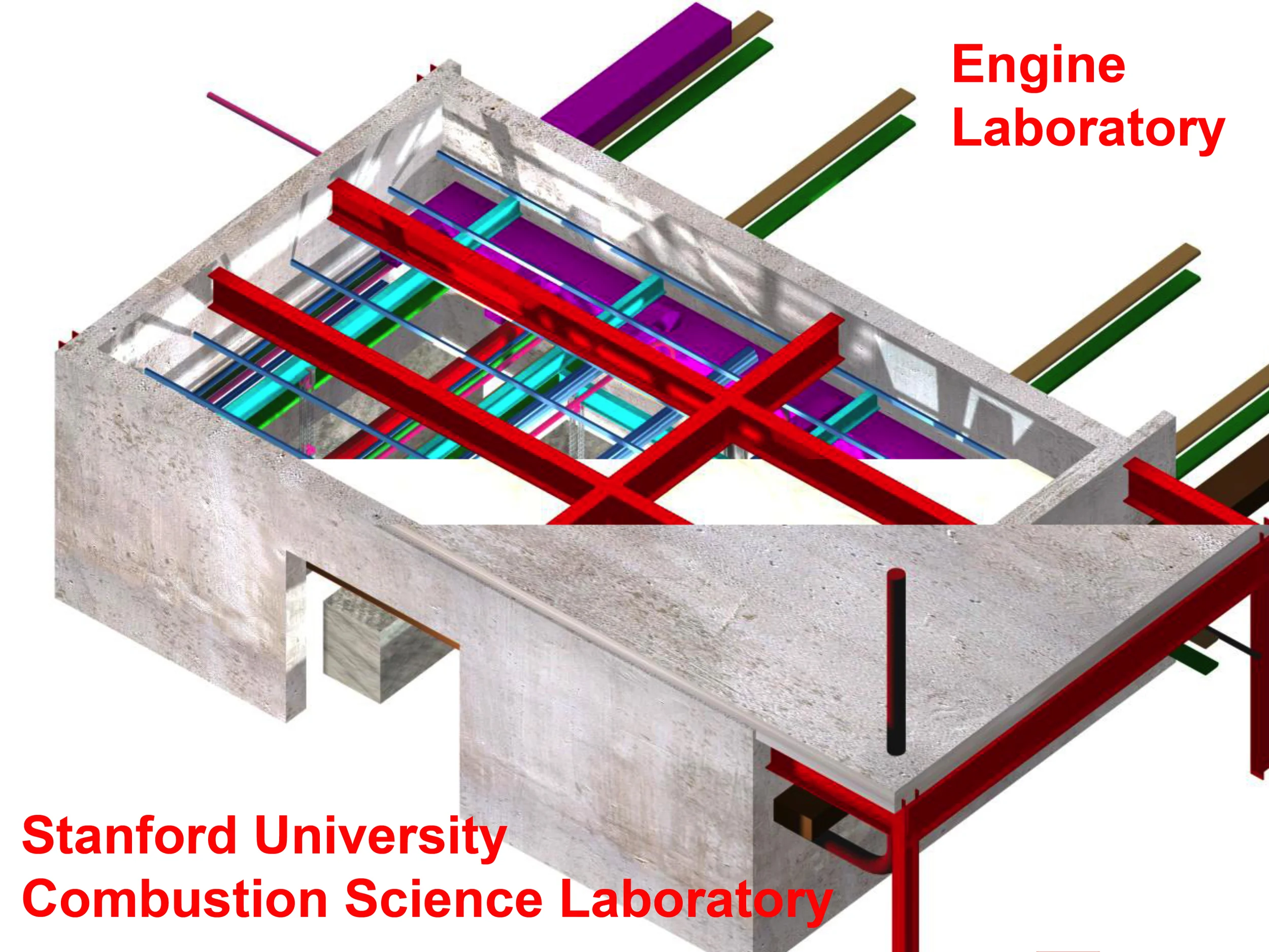
Figure 1: Engine Lab Coordination Model (ACAD ADT R3)- Drawing & Design Coordination by John Millard)
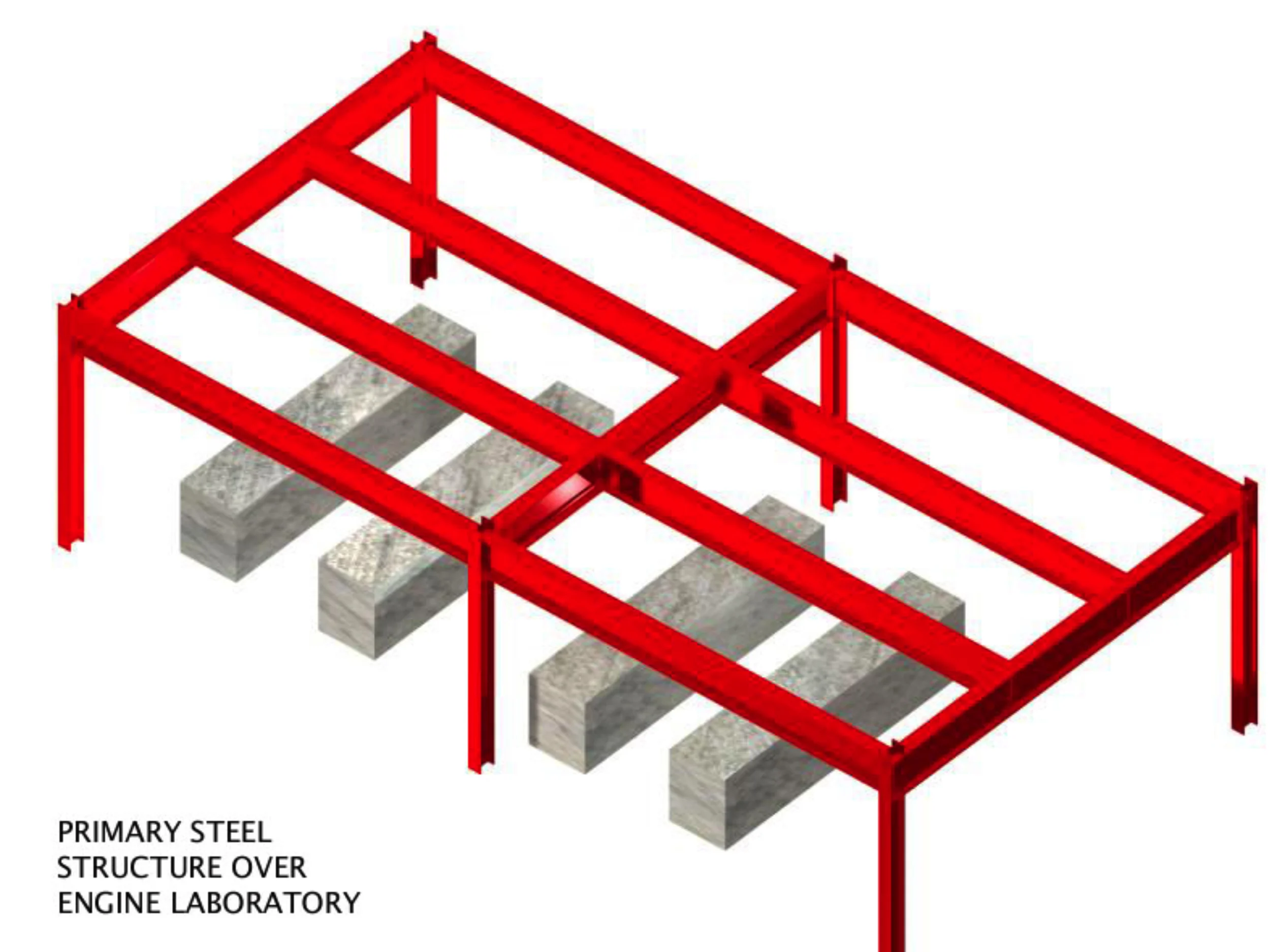
Figure 2: Engine Lab Coordination Model (Primary Bldg. Steel Structure)
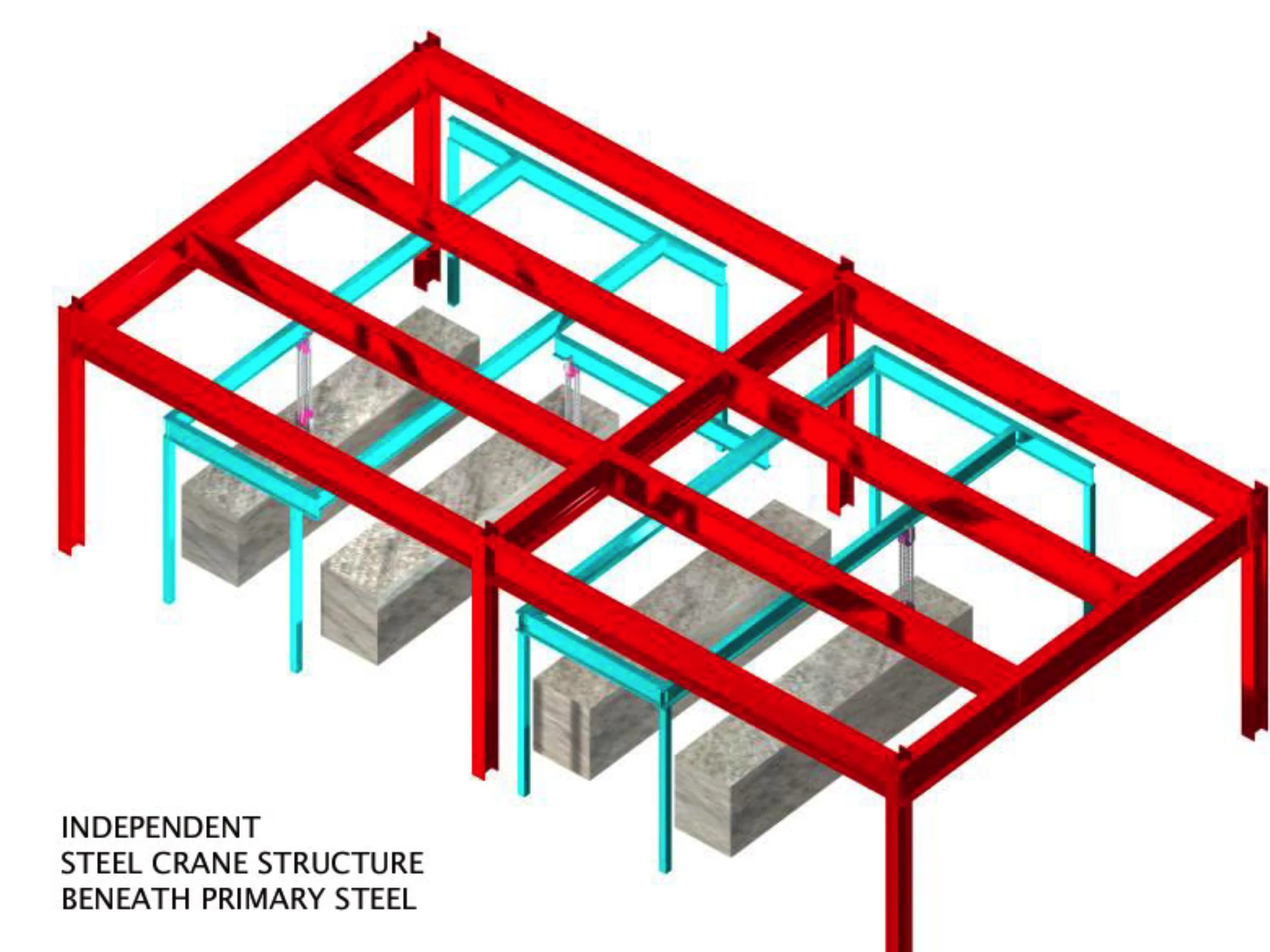
Figure 3: Engine Lab Coordination Model (Traveling Bridge Beam Crane)-
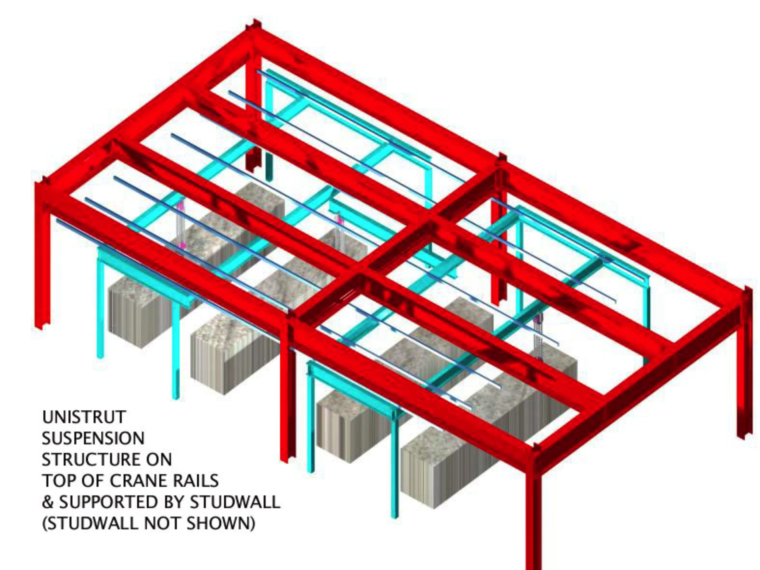
Figure 4: Engine Lab Coordination Model (Crane & Strut)
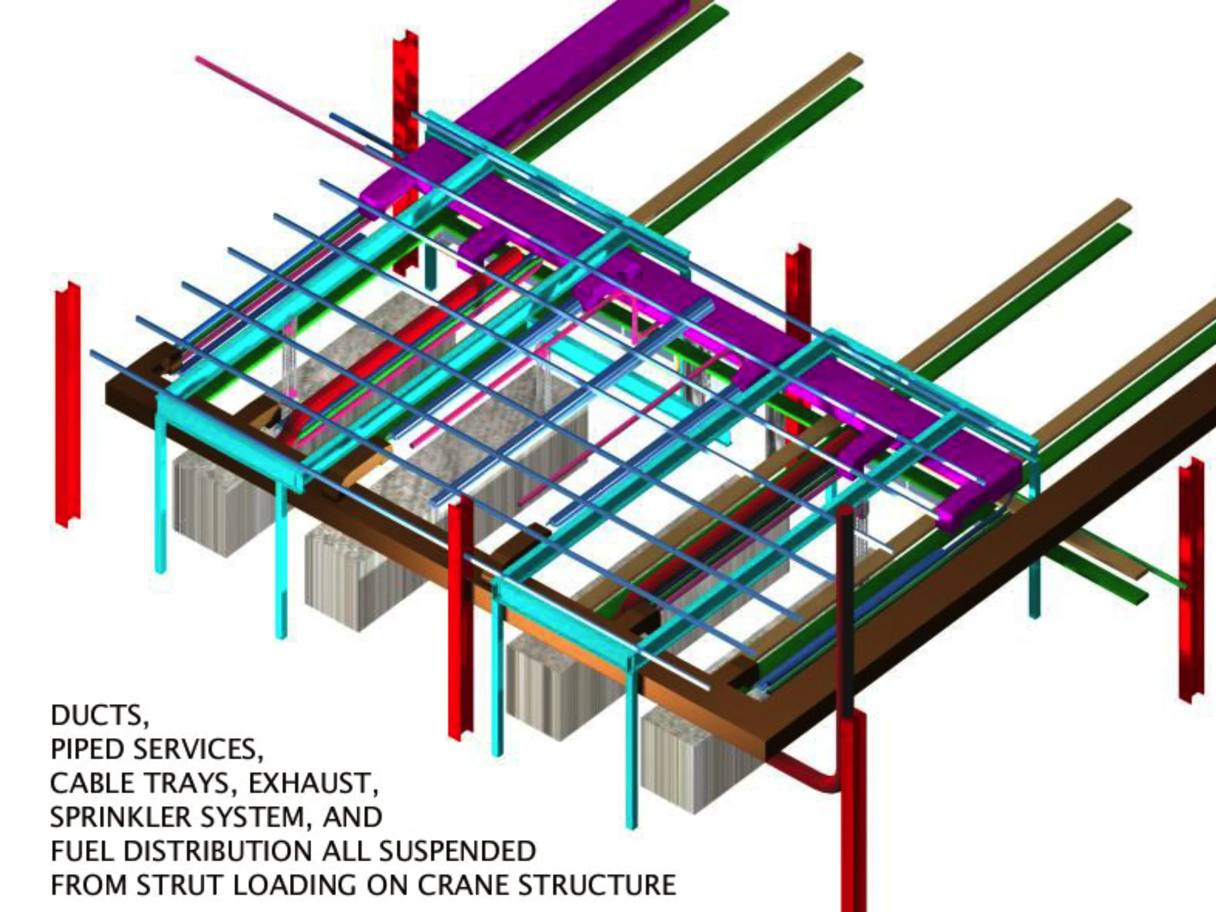
Figure 5: Engine Lab Coordination Model (Ducts, Plumbing, Cable Tray, Dedicated Exhaust, Sprinkler System, Fuel Lines, Strut & Crane)
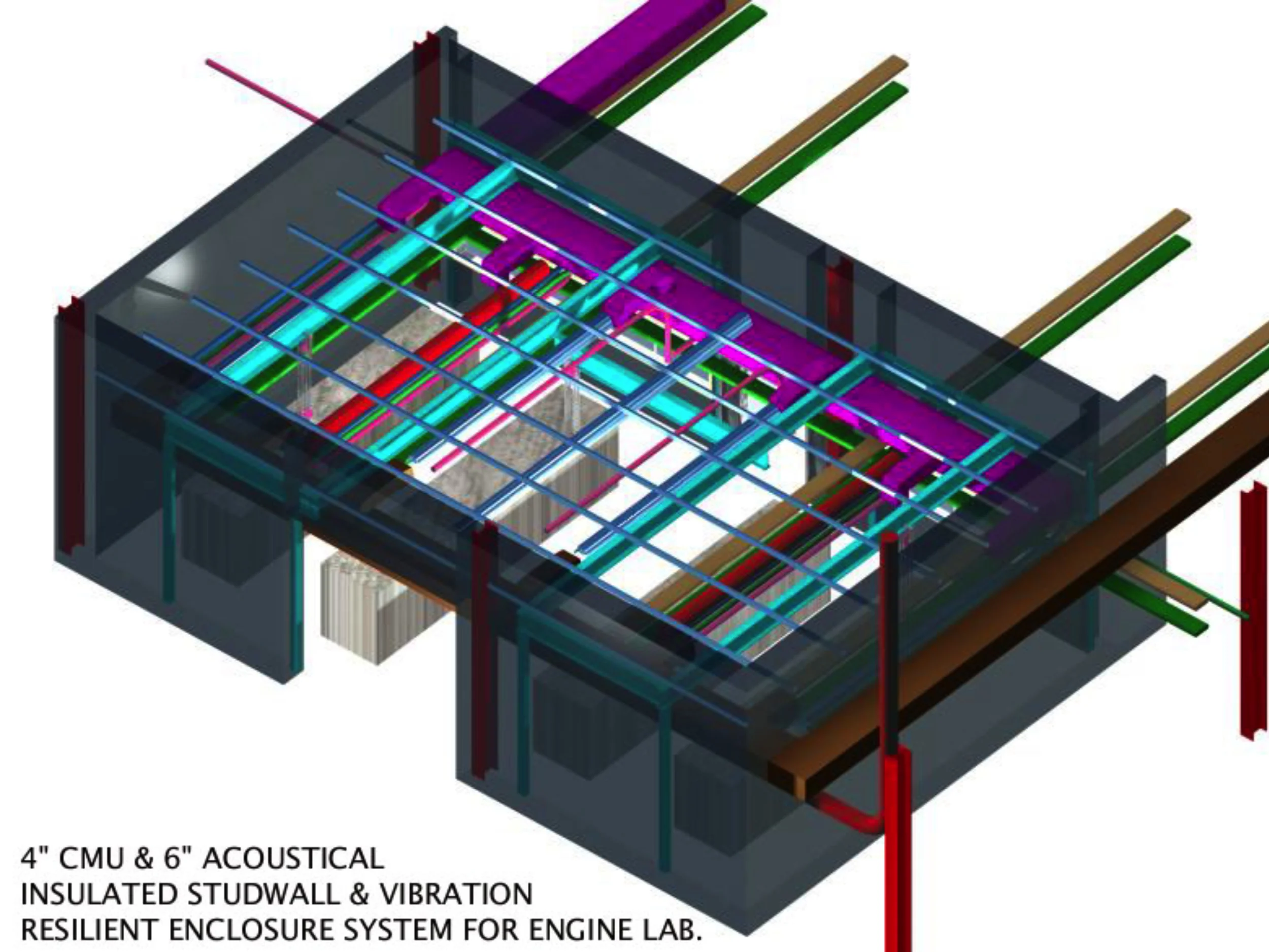
Figure 6: Engine Lab Coordination Model (Ducts, Plumbing, Cable Tray, Dedicated Exhaust, Sprinkler System, Fuel Lines, Strut & Crane)
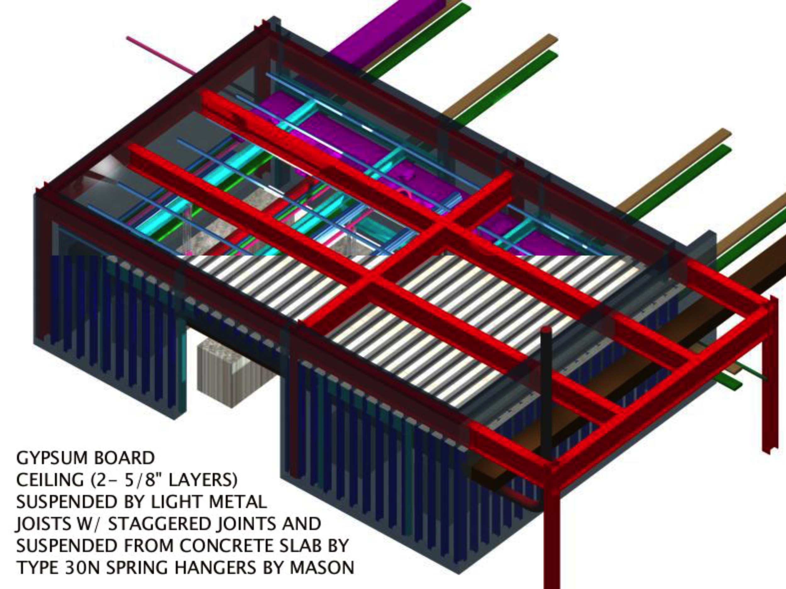
Figure 7: Engine Lab Coordination Model (Resilient Enclosure)
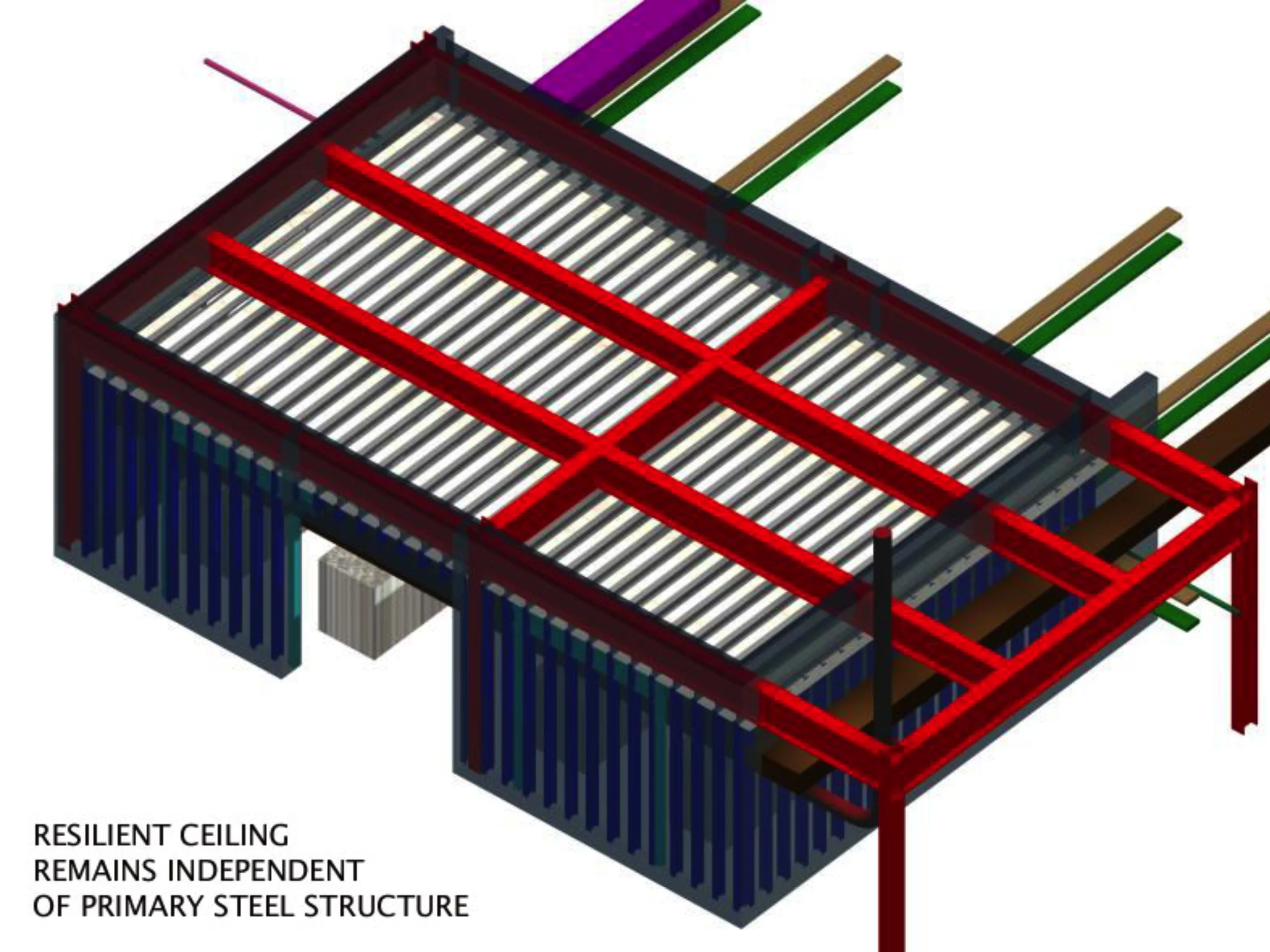
Figure 8: Engine Lab Coordination Model (Resilient Enclosure)
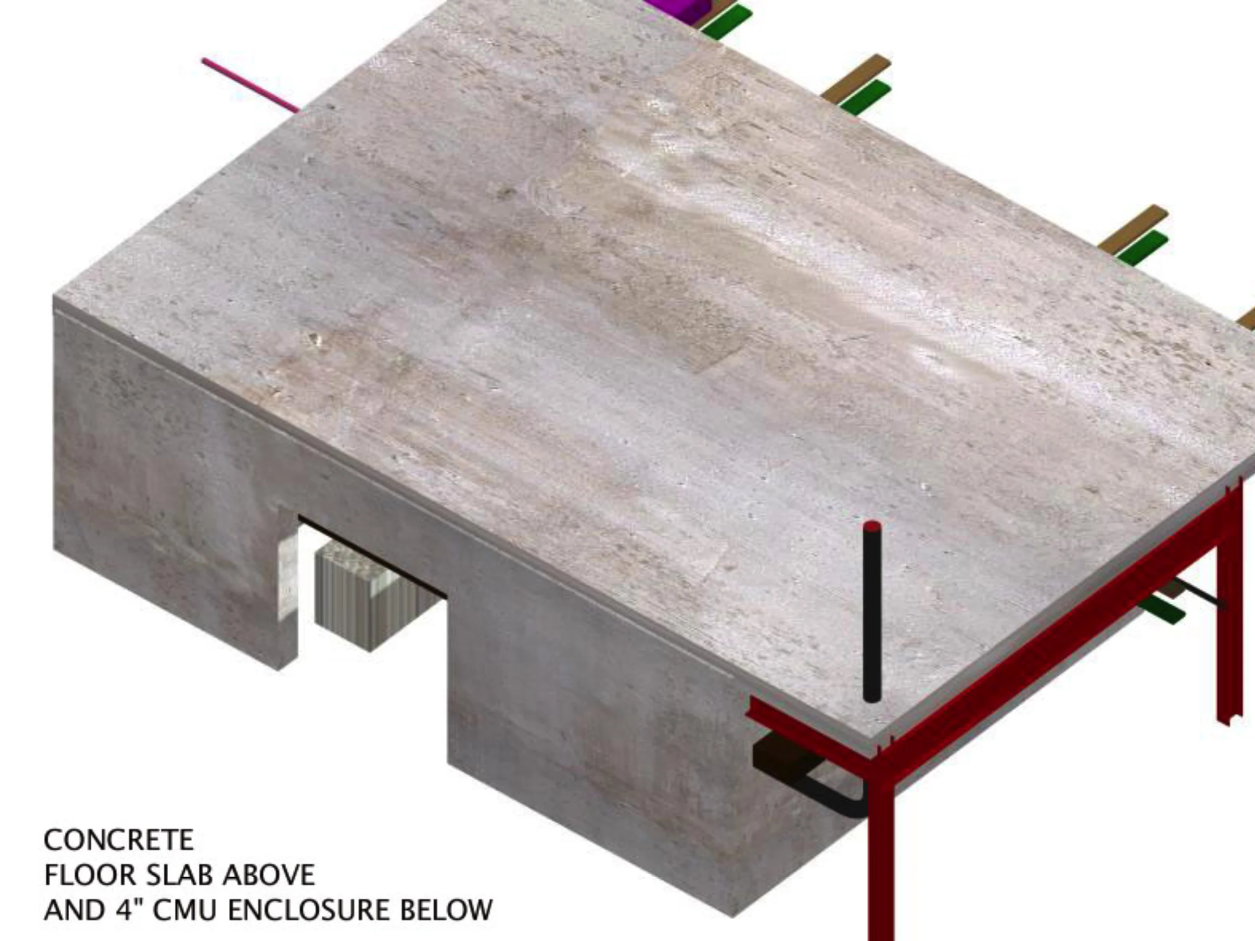
Figure 9: Engine Lab Coordination Model (Fully Enclosed)
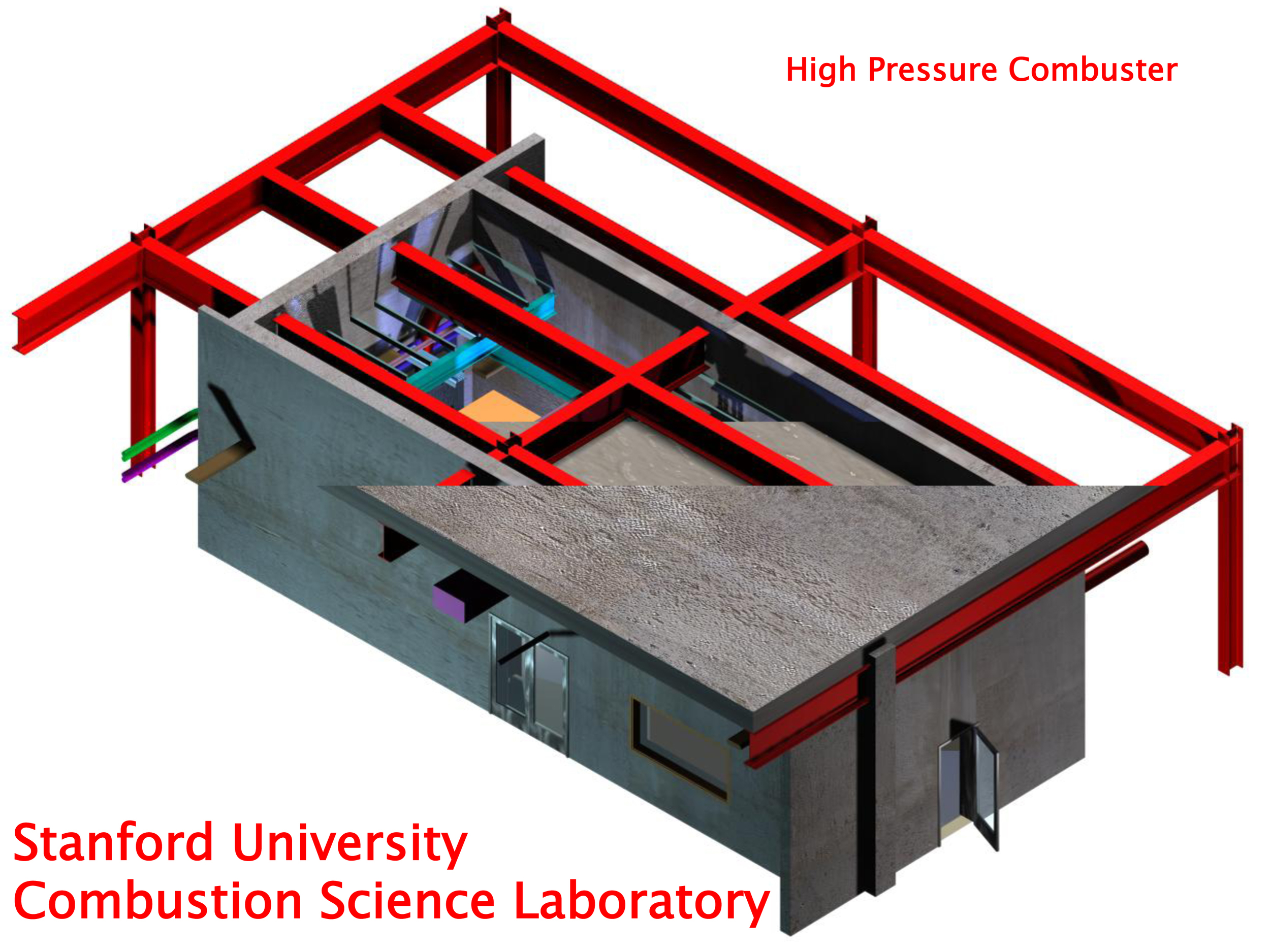
Figure 1: Composite axonometric showing design elements of High Pressure Combuster Laboratory
The type of research carried out in this laboratory:
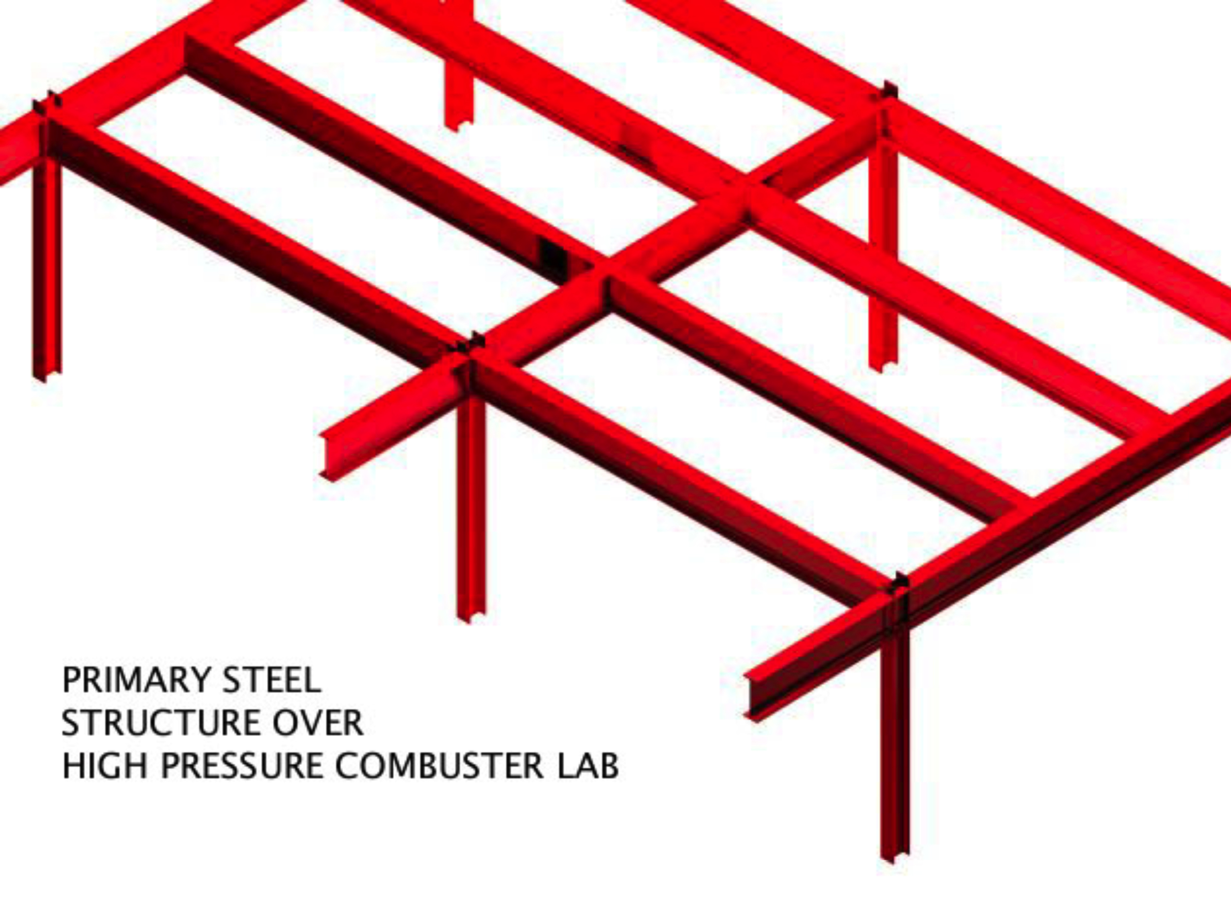
Figure 2: Axonometric showing primary building steel frame
Prevent experimental explosive vibration detonated in this lab from reaching this steel frame and telegraphing noise to the entire building.
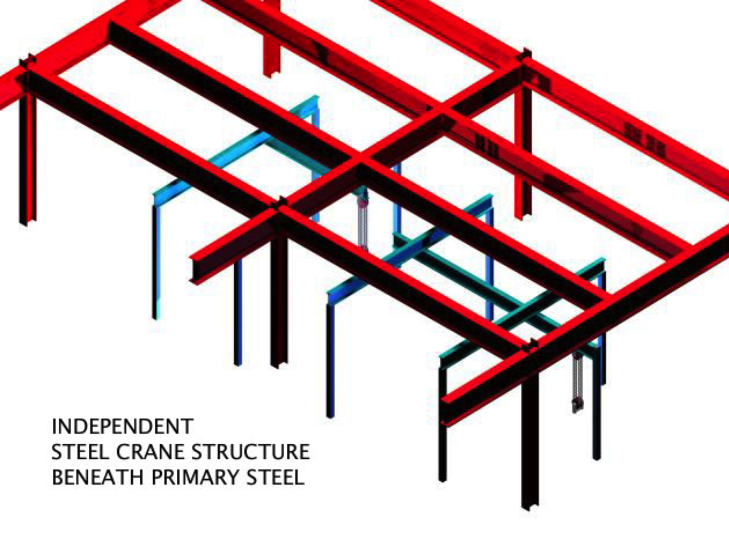
Figure 3: High Pressure Combuster Coordination Model- Primary Structure w/ Traveling Bridge Beam Crane
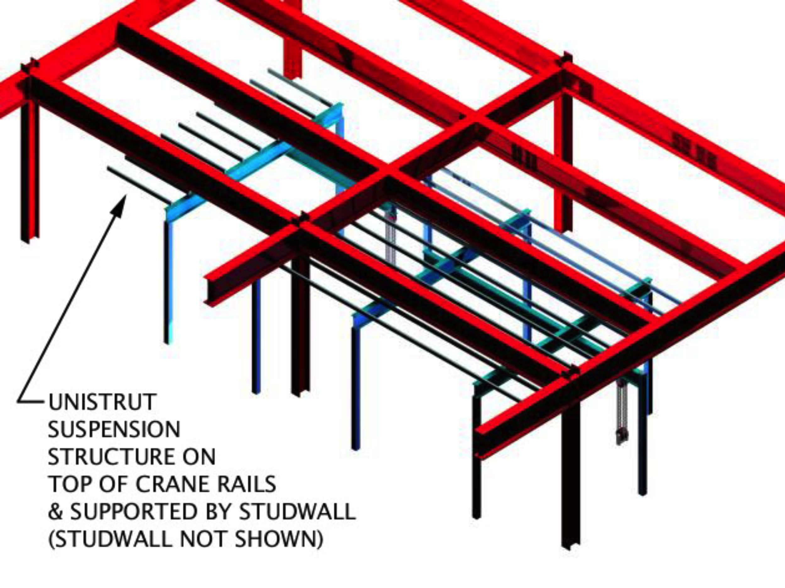
Figure 4: High Pressure Combuster Coordination Model- Crane Layout with Strut Canopy
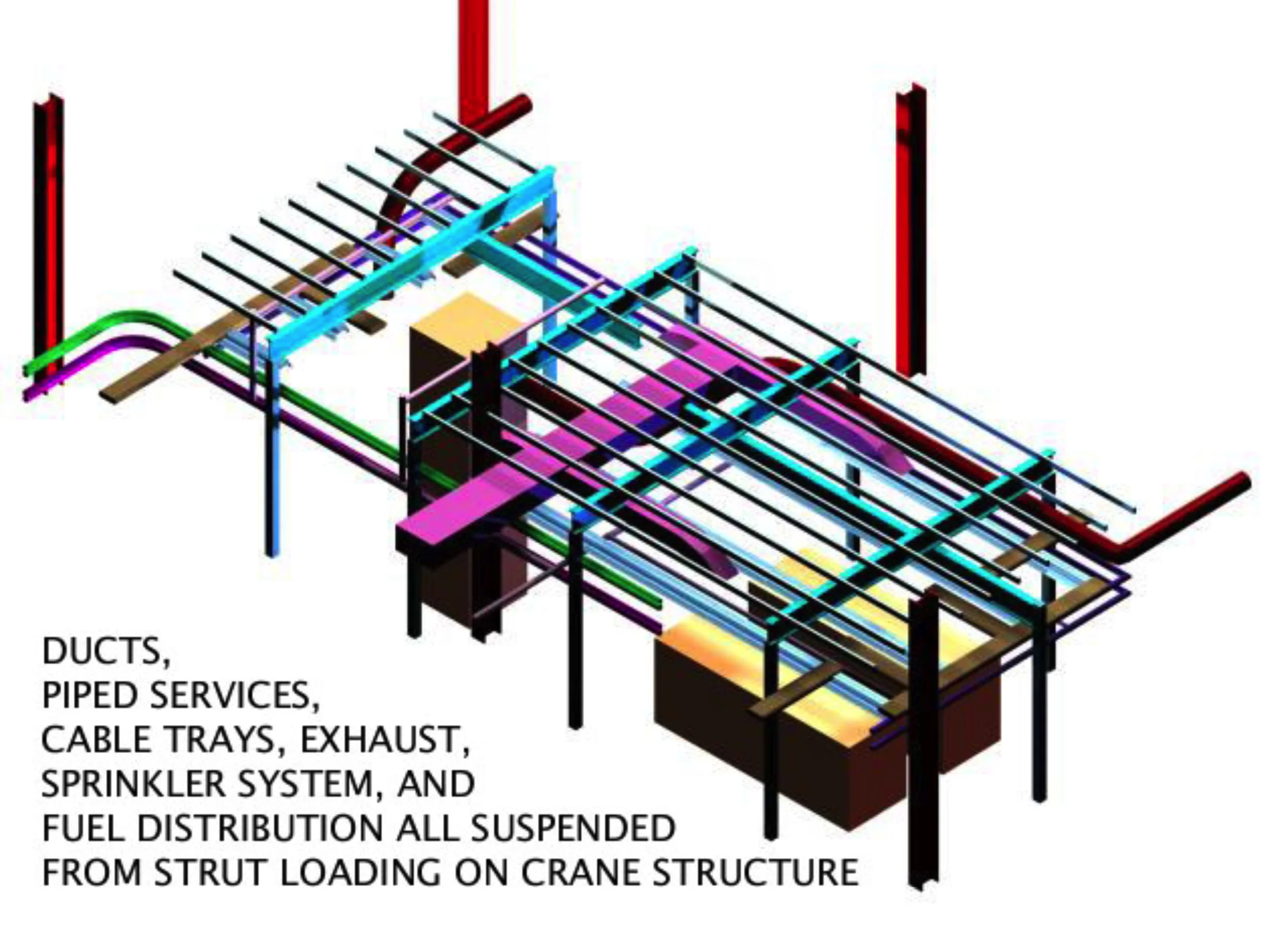
Figure 5: High Pressure Combuster Coordination Model- Ducts, Piped Services, Cable Trays, Exhaust, Sprinkler System, Fuel Distribution, Strut & Crane
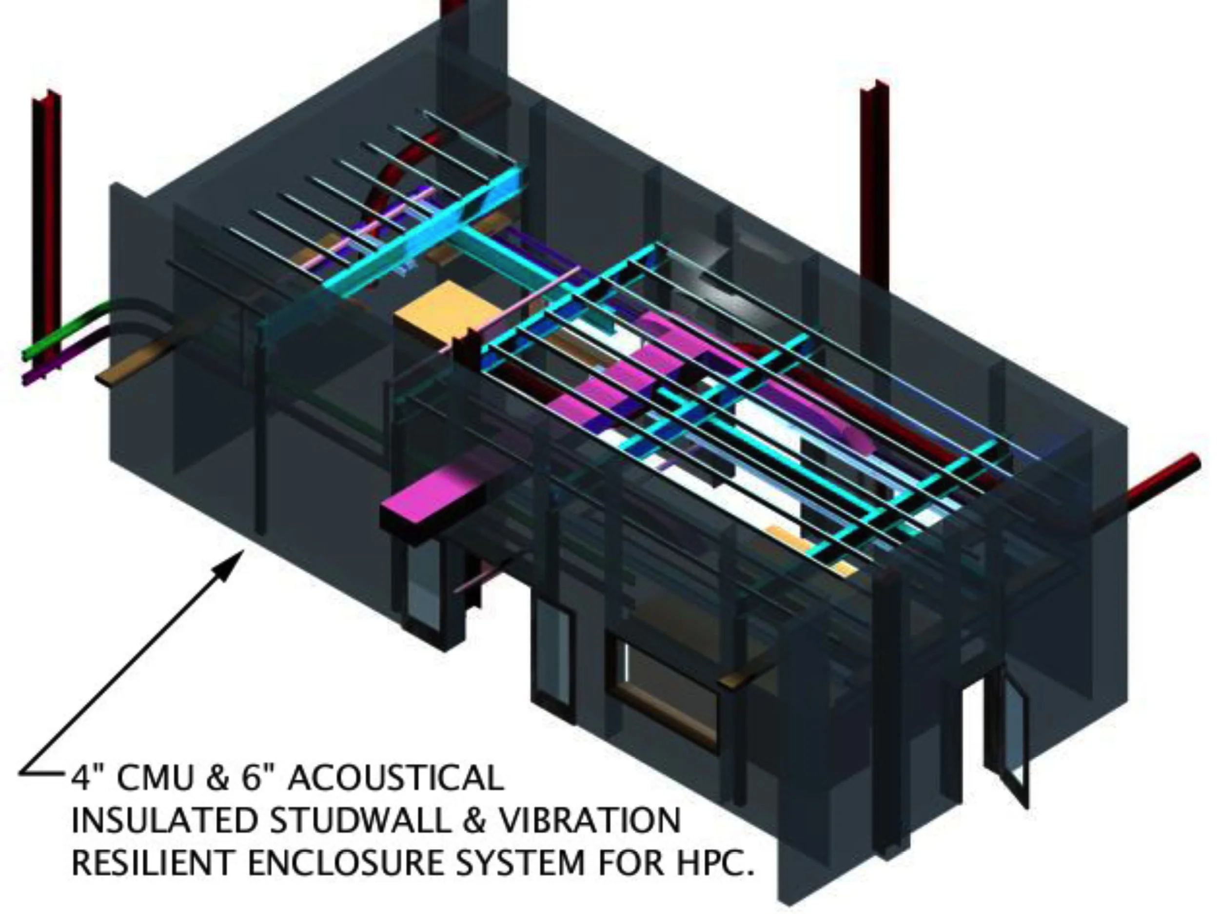
Figure 6: High Pressure Combuster Coordination Model- Resilient Enclosure
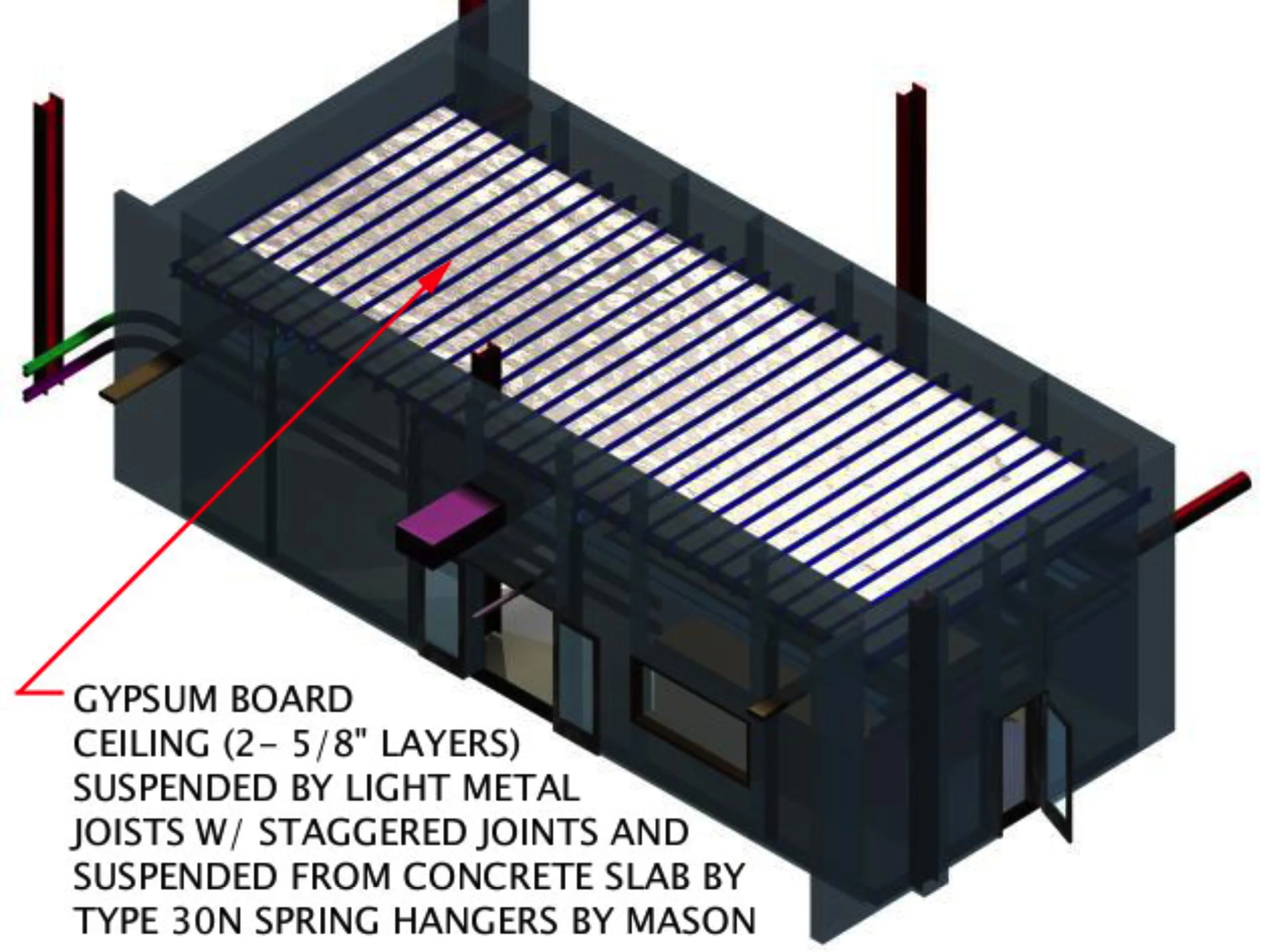
Figure 7: High Pressure Combuster Coordination Model- Resilient Ceiling
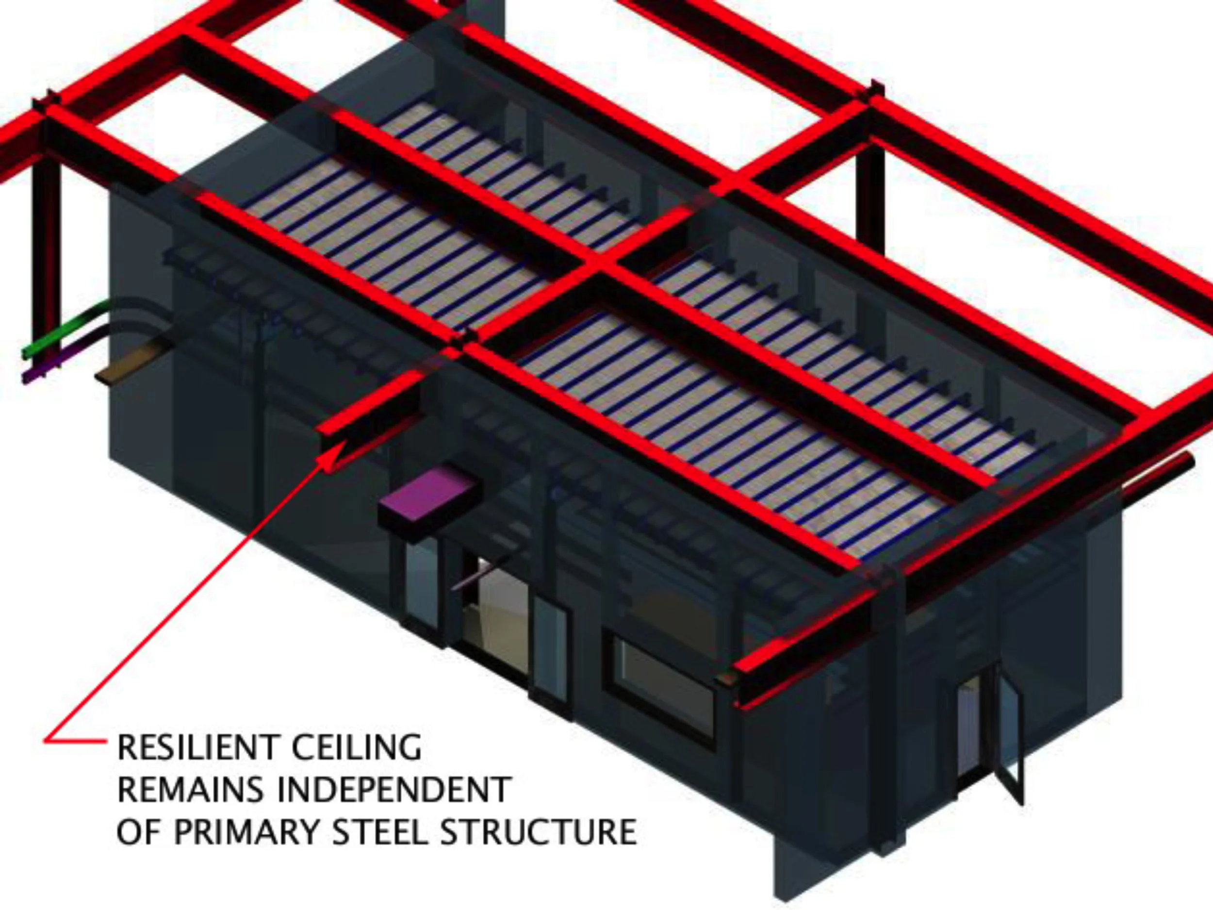
Figure 8: High Pressure Combuster Coordination Model- Resilient Ceiling
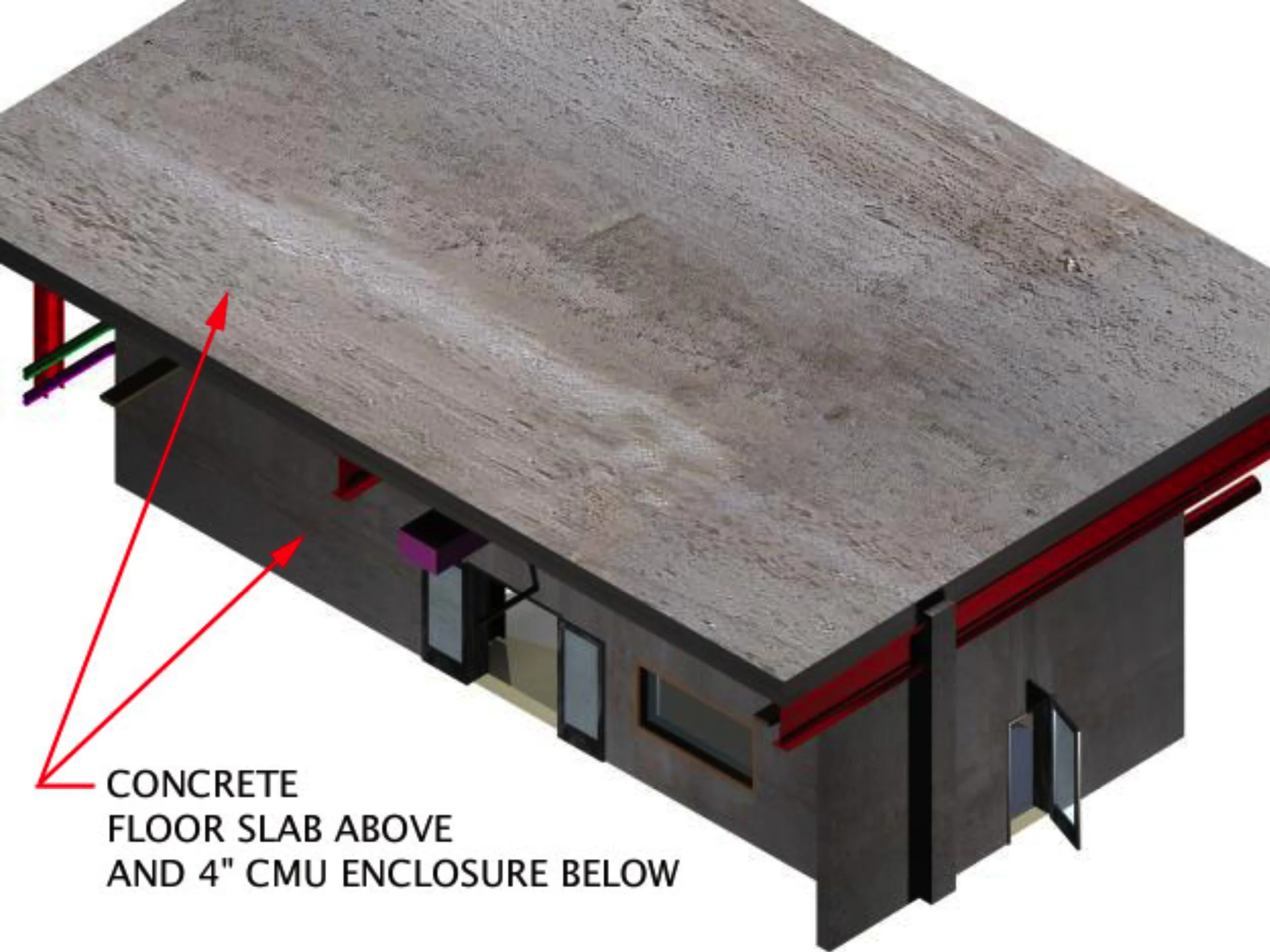
Figure 9: High Pressure Combuster Coordination Model- Fully Enclosed
